1
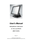
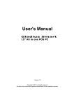
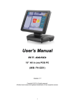
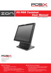
System Manual
Model Name:
AP-3617
Document Version: I
Customer
FEC
Prepared by
Date
Date
_________
FEC
Approved by
Checked &
Approved by
1
AerPOS
User's Manual
Version 0.1
AP-3617
17” Bezel Free Performance POS Terminal
Copyright Notice
This document is copyrighted, © 2013. All rights are reserved. Firich Enterprises Co., Ltd reserves
the right to make improvements of the product described in this manual at any time without notice.
No part of this manual may be reproduced, copied, translated, or transmitted in any form or by
any means without the prior written permission from Firich Enterprises Co., Ltd. Information
provided in this manual is intended to be accurate and reliable. However, Firich Enterprises Co.,
Ltd assumes no responsibility for its use, nor for any infringements upon the rights of third parties,
which may result from its use.
The material in this document is for product information only and is subject to change without
notice. While reasonable efforts have been made in the preparation of this document to assure its
accuracy, Firich Enterprises Co., Ltd, assumes no liabilities resulting from errors or omissions in
this document, or from the use of the information contained herein.
Record of Revision
Date
2013/10/17
Specs Ver. Description
V0.1
Initial
Note
Julie
Safety and Warranty
1. Read these safety instructions carefully.
2. Keep this user's manual for later reference.
3. Disconnect this equipment from any AC outlet before cleaning. Do not use liquid or spray
detergents for cleaning. Use a damp cloth.
4. For pluggable equipment, the power outlet must be installed near the equipment and must be
easily accessible.
5. Keep this equipment away from humidity.
6. Put this equipment on a reliable surface during installation. Dropping it or letting it fall could
cause damage.
7. The openings on the enclosure are for air convection. Protect the equipment from overheating.
DO NOT COVER THE OPENINGS.
8. Make sure the voltage of the power source is correct before connecting the equipment to the
power outlet.
9. Position the power cord so that people cannot step on it. Do not place anything over the power
cord.
10. All cautions and warnings on the equipment should be noted.
11. If the equipment is not used for a long time, disconnect it from the power source to avoid
damage by transient over-voltage.
12. Never pour any liquid into an opening. This could cause fire or electrical shock.
13. Never open the equipment. For safety reasons, only qualified service personnel should open
the equipment.
14. If any of the following situations arises, get the equipment checked by service personnel:
a. The power cord or plug is damaged.
b. Liquid has penetrated into the equipment.
c. The equipment has been exposed to moisture.
d. The equipment does not work well, or you cannot get it to work according to the user’s manual.
e. The equipment has been dropped and damaged.
f. The equipment has obvious signs of breakage.
15. DO NOT LEAVE THIS EQUIPMENT IN AN UNCONTROLLED ENVIRONMENT WHERE
THE STORAGE TEMPERATURE IS BELOW -20° C (-4°F) OR ABOVE 60° C (140° F). IT MAY
DAMAGE THE EQUIPMENT.
Table of Content
Chapter 1
Introduction
1
1
AerPOS ( AP-3617 ) Introduction......................................................................................... 1
A Quick Tour for AP-3617.................................................................................................... 2
AP-3617 Dimension ...................................................................................................... 3
Rear I/O Panel Connectivity................................................................................................. 4
Aer POS AP-3617 Packing List............................................................................................ 5
Chapter 2
Hardware Installation and Upgrading
6
6
2.5” Hard Disk Drive Installation........................................................................................... 6
MSR / Finger Print Reciever / RFID / iButton Installation ..................................................... 7
MB / Heatsink & Smart Fan / Memory Installation ................................................................ 8
Memory (DDRIII RAM) & CPU Installation / MB Pin Define, Battery and Clear CMOS
Setting ................................................................................................................................. 9
COM Port Power Setting.................................................................................................... 10
Integrated VFD / LCM Installation ...................................................................................... 11
17” / 11.6” 2nd Display Installation ...................................................................................... 12
17” 1st Touch Display Installation & Swapping ................................................................... 13
OSD Function and Adjustment........................................................................................... 14
Cash Drawer Installation.................................................................................................... 15
Chapter 3
Software Installation and Setup
16
16
Chipset Driver Installation .................................................................................................. 16
Intel Chipset Installation Utilities for Windows XP ....................................................... 16
Intel Chipset Installation Utilities for Windows 7 .......................................................... 18
.Net Framwork 3.0 Tool Installation.................................................................................... 19
.Net Framework 3.0 Tool for Windows XP .................................................................. 19
VGA Driver Installation....................................................................................................... 21
VGA driver installation for Windows XP ...................................................................... 21
VGA driver installation for Windows 7 ......................................................................... 23
Intel Management Engine Components Driver Installation................................................. 25
VGA driver installation for Windows 7 ......................................................................... 25
LAN Driver Installation ....................................................................................................... 27
Realtek RT8111E LAN Driver Installation for Windows XP ......................................... 27
Realtek RT8111E LAN Driver Installation for Windows 7 ............................................ 28
Audio Driver Installation ..................................................................................................... 28
Realtek ALC887 Audio Driver Installation for Windows XP & Windows 7.................... 28
FEC P-Capacitive/ Resistive Touch Utility (EETI Controller) .............................................. 30
EETI TouchKit Tools Installation ........................................................................................ 30
TouchKit Control Panel for P-Capacitive/ Resistive Touch................................................. 33
Wireless LAN Driver Installation......................................................................................... 34
Wireless LAN Driver Installation for all Windows Operating Systems (Optional) ......... 34
Chapter 4
Specifications
35
35
AP-3617 Specifications...................................................................................................... 35
Chapter 5
Troubleshooting
36
36
Touch Panel Does Not Work....................................................................................... 36
OSD Panel Cannot Work Precisely............................................................................. 36
Cannot Detect SATA Storage HDD/SSD .................................................................... 36
LAN Is Not Functioning Properly ................................................................................. 37
COM1 ~ COM5 Are Not Functioning Properly............................................................. 37
Cash Drawer Port Is Not Functioning Properly............................................................ 37
Appendix A:
Smart Management Tool User Guide
38
38
AerPOS Series AP-3617
Chapter 1
Introduction
AerPOS ( AP-3617 ) Introduction
AerPOS is the perfect combination of reducing the Total Cost Ownership and enhanced quality
requirement for POS system. With the design base on quality, space-effective and performance,
its modularized design helps user no matter on the maintenance but the further upgrade in a very
easy way.
Main Features:
•
The high quality of resistive touch or durable tempered glass of projective capacitive
touch both are IP65 front panel compliant.
•
Desktop solution with high performance is perfect for heavy loading environment.
Mobile platform aims for green and energy saving requirement
•
Modularized design and easy maintenance for the key parts of its system, such as
storage device, CPU module and touch display.
•
With various devices support and sufficient I/O connectivity requirements.
•
Integrated VFD and the 2nd 17” / 11.6” LCD display.
1
AerPOS Series AP-3617
A Quick Tour for AP-3617
17” Touch Display
Validation Hole (Cool Air in)
Power Switch
HDD LED
Smart Management Button
USB Port
Display OSD
Power Switch / Status
Blue LED: Power ON
Red LED: Power Off / Standby
HDD / SATA Status
Orange LED: Operation
Validation Hole
(Hot Air Out)
2.5” SATA Drive
Access
Smart Management
Connection button
MSR
Finger Print Receiver
RFID
i-Button
11.6” / 17” 2nd Display
VFD / LCM
Cable Access
2
AerPOS Series AP-3617
AP-3617 Dimension
H: 386mm
W: 240mm
D: 222mm
W: 410mm
3
AerPOS Series AP-3617
Rear I/O Panel Connectivity
Power USB
12V
USB
COM 5
COM 1
COM 3
VGA
LAN
COM1
Status
DC IN
DC Out
Cash
Drawer
USB
COM2
Status
COM 2
COM 4
USB
Mic In
Line Out
Optional Second IO
Type A
Power USB
12V
Type B
COM 5
USB
Power USB
24V
I/O Port
Connector Type
Description
VGA
Line Out
Mic In
D-sub 15
Earphone connector
Microphone Connector
Connect 2nd LCD screen or CRT monitors
Connect speakers to this port
Connect microphone to this port
LAN
USB
COM 3
RJ-45
A type USB
RJ-45
Connect to Ethernet
Connect to standard A type USB devices
Serial port COM 3—simple COM
RI—NA LED ; 5V—Green Light ; 12V – Orange Light
COM 4
RJ-45
Serial port COM 4
RI—NA LED ; 5V—Green Light ; 12V – Orange Light
COM 1
COM 2
COM Status
D-sub9
D-sub9
LED
Serial Port COM 1
Serial Port COM 2
RI—NA LED ; 5V—Green Light ; 12V – Orange Light
USB
Cash Drawer
DC out
A type USB
RJ-11
DC out connector
Connect to standard A type USB devices
Connect to 12V Cash Drawer
12V DC out put connect to 12V peripherals or devices
DC IN
DC IN connector
Connect the 12V power adaptor to this port
4
AerPOS Series AP-3617
I/O Port
Connector Type
Description
Optional Second IO Board is only available as pre-installed in FEC factory
Type A
Power USB
Power USB 12V
(optional)
Connect to standard A type USB devices with 12V
Power Supply
COM 5
D-sub9 (optional)
Serial Port COM
USB
A type USB (optional)
Connect to standard A type USB devices
Power USB 24V
(optional)
Connect to standard A type USB devices with 24V
Power Supply
Type B
Power USB
Before you unplug the power USB cable from I/O panel, please ensure unplug the A/C Cord in
advanced.
Aer POS AP-3617 Packing List
Standard
Optional & Peripherals
1
2
17” AP-3617 AerPOS Touch Terminal
12V 150W Power Adaptor
1
2
Optional IO Board
RJ-45 to D-sub9 Convert Cable
3
AC Power Cable
3
MSR / RFID / Finger Print Receiver / I-Button
4
20x2 VFD / 20x2 LCM / 240x64 LCM
5
17” / 11.6” 2
6
Wireless Lan Module
5
nd
Display Bracket
AerPOS Series AP-3617
Chapter 2
Hardware Installation and Upgrading
Do not remove the Display Module without switch off the terminal.
Power must be switched off and power cord must be unplugged. Every
time you service the system, please be aware of this.
2.5” Hard Disk Drive Installation
1. Turn off power and remove power cord from the terminal
2. Unscrew the
maintenance door at the
front side of the terminal
body
3. Flip the maintenance
door and Extract 2.5”
SATA storage bracket
out
(no cable connected)
4. Place storage driver on
the bracket and fasten it
with 4 screws.
5. Restore the maintenance door to the system.
6. Fix the maintenance door with a screw.
7. Connect power cord to the system.
6
AerPOS Series AP-3617
MSR / Finger Print Reciever / RFID / iButton Installation
1. Remove the plastic cover
at the back of Touch
Display Module
2. Insert the MSR / RFID /
Finger Print Receiver / Ibutton Module into USB AType Connector. Fix the
Touch Display Module with
one screw.
3. Make sure the USB connected and screw is fastened well.
4. If you are looking for the detail Utility of MCR, Finger Print Reader, I-button Reader,
RFID Reader, please contact FEC’s FAE.(Please refer to FEC website for more
information, http://www.fecpos.com )
7
AerPOS Series AP-3617
MB / Heatsink & Smart Fan / Memory Installation
1. Remove back cover of the
terminal by two screws on
the top side.
2. Anther two screws at the
both side of MB Module
should be removed for the
further disassembly.
3. Lift up and Pull out the MB
Module from the Terminal
Chassis.
DDR-3 204 Pin
Memory
Smart Fan, Heatsink
CPU & Chipset
Golden Finger
8
AerPOS Series AP-3617
4. During the MB installation,
Please Make sure the MB
Golden finger is well connected
with IO Board Slot.
Memory (DDRIII RAM) & CPU Installation / MB Pin Define,
Battery and Clear CMOS Setting
1.
Disassembly the MB Module, then Memory installation can be done from the top side
of MB Module. CPU installation has to remove Thermal Fan Module by 2 screws, after
the CPU installation, please ensure the thermal pads between CPU, chipset and
heatsink are well contacted.
DDR-3 204Pin
Memory Slot
Smart Fan Heatsink
CPU & Chipset
2.
According to the MB on-board connectors or golden finger pin define and Battery
Setting, CMOS Clear, please refer to the FH-H611 MB Manual. (Will update soon)
9
AerPOS Series AP-3617
COM Port Power Setting
AP-3617 COM Port Power can adjust via BIOS or Smart Management Tool.
5. COM Port Power Configuration:
6. Advance > Super IO Configuration > Serial Port 1 or 2 Configuration
Advance > F81214 Super IO Configuration > Serial Port 3 or 4 Configuration
7. COM 1 or 2 or 3 or 4 Port Power > Enable
COM 1 or 2 or 3 or 4 Power Type > +5V or +12V (select the proper power output for
proper com port devices)
If you need more information about the BIOS setting or Smart Management Setting, please
refer to the MB Manual or Smart Management Manual or contact FEC’s FAE.
10
AerPOS Series AP-3617
Integrated VFD / LCM Installation
1. Remove the VFD Plastic
cover from the terminal
2. Connect the COM 3
internal cable between
Terminal and VFD / LCM
Module and install the
VFD/ LCM module with
Terminal. Fasten one
screw back and make sure
VFD/LCM module is fixed.
3. VFD is connected to the COM3 (COM3 has internal power which has been pre-set as
12V power)
** Please note When VFD/LCM is integrated, please remove the device which connects
to the external COM3 on Rear IO panel to prevent I/O interrupt.
4. Adjust the VFD / LCM
angle into proper position.
11
AerPOS Series AP-3617
17” / 11.6” 2nd Display Installation
1.
Remove the VFD plastic
cover
2.
Assemble the 2nd screen
with bracket with 4
screws
3.
Assemble the 2nd Screen
with bracket to Terminal.
4.
Fasten 3 screws
(1 on top, 2 underneath)
5.
Connect the monitor to
AP-3617 by VGA & DC
cable
12
AerPOS Series AP-3617
17” 1st Touch Display Installation & Swapping
1.
Release 1 thumb screw at
the back side of Display
2.
Lift the Display Module up
to disassemble from the
main unit of terminal
3.
Display and main body
units are separated.
4.
Reverse the process can
assembly back the Touch
Display Module.
** please make sure the
touch display module is
firmly connected to the
docking slot **
**Note**
During the process of disassembly and installation, please ensure the terminal is
“Power Off” and remove AC cord. “Hot Swap” could casue the internal protection to
block touch display functionality.
13
AerPOS Series AP-3617
OSD Function and Adjustment
OSD function and adjustment
Back Light Power (finger touch for 5 seconds)
Back Light Power On – Blue LED indication
Back Light Power Off – Red LED indication
P-CAP Touch re-calibrates during Power Off and On
Button Down (finger touch for 2 seconds)
Back Light Dimmer Down
Button Up (finger touch for 2 seconds)
Back Light Dimmer Up
No Function / Reserve Function for AerTouch Monitor
14
AerPOS Series AP-3617
Cash Drawer Installation
Before connecting the cash drawer to the AP-3617, please make sure the drive voltage and cable
pin assignment of the cash drawer matches the definition of the cash drawer port of AP-3617.
Power USB
12V
COM 5
USB
COM 1
COM 3
VGA
LAN
COM1
Status
DC IN
DC Out
Cash
Drawer
USB
COM2
Status
COM 2
COM 4
USB
Mic In
Line Out
Note: If the cash drawer cannot be detected by the system, please refer to trouble shooting.
Up to two cash drawers may be driven from this port. Driving voltage of the solenoid is
DC+12V. I/O port 284 is used for drawer operation. A test program is supplied, for Linux and
Windows, source code of which is available on request by software developers.
Byte 1
Byte 2-3
Byte 4-5
Byte 6
Byte 7
Byte 8
Byte 9
(0xA0)
(0xA1 ~ 0xA2)
(0xA3 ~ 0xA4)
(0xA5)
(0xA6)
(0xA7)
(0xA8)
Value
0x00
0xA07
0xA07
0xFD
0xFB
0xFF
0x01
Description
GPIO / 0x01 or DIO / 0x00.
Output address.
Inpute address.
Open cashdrawer1 value.
Open cashdrawer2 value.
Close cashdrawer value.
Cashdrawer status mask.
15
AerPOS Series AP-3617
Chapter 3
Software Installation and Setup
AP-3617 comes with a variety of drivers for different operating systems.
You can download all the necessary drivers and utilities from http://www.fecpos.com.
Or send an e-mail to the Customer Service Department of FEC for further assistance.
Chipset Driver Installation
Intel Chipset Installation Utilities for Windows XP
1. Download drivers from website or insert the Driver CD into your CD ROM Drive.
2. Execute Setup.exe and Click Next.
16
AerPOS Series AP-3617
3. Read the License Agreement and click Yes & Click Next and the drivers for the Intel Chip
set will install.
4. Click Next and choose “restart computer”, then click to Finish.
17
AerPOS Series AP-3617
Intel Chipset Installation Utilities for Windows 7
1. Download drivers from website or insert the Driver CD into your CD ROM Drive.
2. Execute Setup.exe and Click Next.
3. Read the License Agreement and click Yes & Click Next and the drivers for the Intel Chip
set will install.
4. Click Next and choose restart computer for finishing the Chipset Driver, click to Finish.
18
AerPOS Series AP-3617
.Net Framwork 3.0 Tool Installation
.Net Framework 3.0 Tool for Windows XP
1. Download drivers from FEC website or insert the Driver CD into your CD ROM Drive.
2. Double click Setup.exe, and Click Next to start tool installation
3. Execute dontnetfx3 for further setup
19
AerPOS Series AP-3617
4. choose I have read and ACCEPT the terms of the license Agreement and click Install for
the following steps
5. Click the message pop out to check for the detail process. Finally, click Exit to finish the
installation.
20
AerPOS Series AP-3617
VGA Driver Installation
VGA driver installation for Windows XP
1. Download drivers from website or insert the CD into your CD ROM Drive.
2. Execute Steup.exe
3. Select Next and click Yes of License Agreement Page.
21
AerPOS Series AP-3617
4. Select Next to continue driver installation.
5. Finally, Finish and Restart the system
22
AerPOS Series AP-3617
VGA driver installation for Windows 7
1. Download drivers from website or insert the CD into your CD ROM Drive.
2. Execute Steup.exe and select Next
3. Click Yes of License Agreement Page.
4. Select Next to continue driver installation.
23
AerPOS Series AP-3617
5. Finally, Finish and Restart the system
24
AerPOS Series AP-3617
Intel Management Engine Components Driver Installation
VGA driver installation for Windows 7
1. Download drivers from website or insert the CD into your CD ROM Drive.
2. Execute Steup.exe
3. Select Next and click Yes of License Agreement Page.
4. Select Next to continue driver installation.
25
AerPOS Series AP-3617
5. Finally, Finish and Restart the system
26
AerPOS Series AP-3617
LAN Driver Installation
Realtek RT8111E LAN Driver Installation for Windows XP
1. Download drivers from website or insert the CD into your CD ROM Drive.
2. Execute Setup.exe.
3. Click Next to continue
4. Click Finish to complete the installation procedure.
27
AerPOS Series AP-3617
Realtek RT8111E LAN Driver Installation for Windows 7
1. Download drivers from website or insert the CD into your CD ROM Drive.
2. Execute Setup.exe.
3. Click Next to continue and Finish to complete the installation procedure.
Audio Driver Installation
Realtek ALC887 Audio Driver Installation for Windows XP &
Windows 7
1. Download drivers from website or insert the CD into your CD ROM Drive.
2. Double click Setup.exe, and Click Next to continue
28
AerPOS Series AP-3617
3. Click Finish and restart the system.
29
AerPOS Series AP-3617
FEC P-Capacitive/ Resistive Touch Utility (EETI Controller)
FEC Projective – Capacitive Touch Utility Introduces:
1. Mode of FEC Capacitive Touch Panel and default settings
2. EETI TouchKit Tools Installation
Mode of FEC P-Capacitive/ Resistive Touch Panel
Win XP, POS Ready 2009
Mouse Mode
Touch Mode
Yes
Driver Needed
N/A
Win7, POS Ready7
Yes
Driver Needed
Yes
No Driver Needed
EETI TouchKit Tools Installation
EETI TouchKit Tools Installation for Windows XP
1.
Down load Touch Kit for WinXP from FEC website.
2.
Execute Setup.exe
3.
Click Next
4.
Click Next
30
AerPOS Series AP-3617
5.
Click Next and do not chosse RS232
6.
Slect None
31
AerPOS Series AP-3617
7.
Click Next for further installation process
8.
Slect No
32
AerPOS Series AP-3617
TouchKit Control Panel for P-Capacitive/ Resistive Touch
This section explains the different options in the TouchKit control Panel.
Tools tab
P-Capacitive
Resistive
Do not need to calibrate the touch screen with the
4 Points.
The tools tab allows you to below calibrate
the touch screen with the 4 Points.
33
AerPOS Series AP-3617
:
Wireless LAN Driver Installation
Wireless LAN Driver Installation for all Windows Operating
Systems (Optional)
1. Download drivers from website or insert the CD into your CD ROM Drive.
2. Run Setup.EXE
3. Click Next
34
AerPOS Series AP-3617
Chapter 4
Specifications
AP-3617 Specifications
Aer POS
AP-3617 Performance
Chipset
Processor
Memory
Main
Specifications
Intel Sandy Bridge H-61
Intel Dual Core Celeron G540 2.5G
Intel i3 2120 3.3G
Intel i5 2400S 2.5G
DDR3 Standard 2GB,
Max 8GB
Power Supply
12V 150W
Thermal
Smart Fan
Storage Device
1 x 2.5” SATA Driver Bay
Speakers
Display Design
Touch
Touch
Display
Backlight
Internal Speaker 2W x 2
17” True Flat (Ultra Slim) Bezel Free
Projective-Capacitive
5W Resistive
(Tempered Glass)
LED
LED
Brightness
250 nits / 350 nits
30 K hours / 50 K hours
Backlight MTBF
MSR
Track 1/2/3 , USB interface
Finger Print Receiver Optical Finger Print Receiver, USB interface
Peripherals
&
Optionals
RFID Reader
13.56M Hz RFID reader , USB interface
I - Button Reader
USB interface
Optional COM Port
Additional Stand USBx1; COM 5; 12V Power USB x 1
Wireless LAN
802.11.b.g.n wireless LAN , USB interface
VFD
(Integration Type)
(Integration Type)
(Integration Type)
(Integration Type)
LCM
2nd Display
35
20x2 (9mm) Character Mode
20 x 2 Character Mode
240x64 Graphic Mode
11.6” / 17” 2nd Monitor
AerPOS Series AP-3617
Chapter 5
Troubleshooting
Please note that the following troubleshooting guide is designed for engineer who has strong
computer hardware knowledge or Engineers and Maintenance.
Touch Panel Does Not Work
A)
Check “Touch Display Module” is connected well with terminal.
B)
Check HID USB touch device is detected by OS.
C)
(Resistive Touch) Check if the EETI driver or the TouchKit driver has been properly
installed. Or try to re-install again (Please refer to the EETI driver and touch kit
installation).
D)
(Capacitive Touch) Check if the FEC-AUO Capacitive touch is automatically detected by
Windows 7, or properly installed the touch driver in Windows XP.
E)
(Capacitive Touch) Please do not keep the capacitive touch in high humidity and
condensing environment, such as out door or bathroom, where might affect the touch
performance or might need to be calibrate more frequently.
F)
Check if the cable connects well between touch panels and touch controller
G)
(Capacitive Touch Calibration) Reboot the system, and the Capacitive Touch can be
calibrated automatically.
OSD Panel Cannot Work Precisely
A)
Please touch each single OSD button for more than two seconds in order to trigger the
function.
B)
Make sure the finger is not touching more than one button each time.
Cannot Detect SATA Storage HDD/SSD
A)
Make sure storage device is well connected in the SATA Connector.
B)
HDD FFC cable is not connected properly to the main board or it could be defective.
C)
Check CMOS setup, set SATA HDD to Auto Detect.
D)
On-board SATA port could be defective.
36
AerPOS Series AP-3617
LAN Is Not Functioning Properly
A)
Check if the LAN driver is installed properly.
B)
Check if there are any IRQ conflicts.
C)
Check if the RJ45 cable is properly connected.
D)
The on-board LAN chip could be defective.
COM1 ~ COM5 Are Not Functioning Properly
A)
Check if the I/O ports are enabled in the CMOS setup.
B)
Check if there are any IRQ conflicts.
C)
The main board or I/O board could be defective.
D)
(Reminder) The COM3 is shared by the read I/O and VFD, if you connector the VFD,
please remove the device which is connected with external COM3.
Cash Drawer Port Is Not Functioning Properly
A)
Make sure the pin assignment matches between the cash drawer and the RJ11 cash
drawer port.
B)
Verify if the digit I/O port address and bit are correct.
C)
The main board could be defective.
37
AerPOS Series AP-3617
Appendix A:
Smart Management Tool User Guide
Smart Management Tool is FEC latest hardware management engine built in AerPOS &
BP-500. With this tool, user could easily access the data inside the system that could
user to identify the status and error during operation.
1. Move this Smart Management.exe to Desktop or any preferred location in your system
(Windows XP & Windows 7 only)
2. Double click the .exe file to activate Smart Management as the following picture.
3. Press the Smart Management button aside the AP-3617 for 5 seconds to enter the
Terminal Status. (This button is just above the external USB connector, Please make
sure you did not press the Power Button or HDD LED)
38
AerPOS Series AP-3617
Please refer to the following definition table for the information showed on the Terminal
Status
Item
Description
MB Version
Shows the M/B version
BIOS Version
Shows the BIOS version of the M/B
IO Version
Shows the firmware version on the I/O board
Display Version
Shows the firmware version on the Display board (AerPOS
only)
Operation Service
Shows the time this system has been powered up
Hours
Stand-by Service
Shows the time this system has been connected to A/C input
Hours
Abnormal On/Off
Shows the times this system has been force disconnect with
Count
A/C input
ON/OFF Total
Shows the times this system has been power on & off
normally
System Operation
Shows the latest time the system has been operated
Hours
Display Module Plug in Shows the times the display module has been re-plugged
Time
(AerPOS only)
Total Display Module
Show the time the display module has been connected with
Standby Hours
the system & the system has been connected to A/C input
(AerPOS only)
Total Back Light Hour Show the time the backlight has been used (AerPOS only)
Each data would be recorded after the system is shutdown normally, for any incorrect
operation or force shutdown, only Abnormal On/Off Count & ON/OFF Total will be
recorded, the rest data will missed.
4. User could monitor the Thermal & Fan Status inside the system by clicking the icon
Thermal.
39
AerPOS Series AP-3617
5. User could monitor the power status on the M/B by clicking the icon POWER STATUS.
Item
CPU Vcore Status
MB Battery Voltage
12V Voltage Status
DC In-Voltage
DC In-Current
DC in-Power
Consumption
Description
Shows CPU Vcore status
Shows the Voltage of M/B battery (If the data of current is too
low, please contact FEC Service Department for battery
replacement)
Shows the voltage of 12V on the M/B
Shows the voltage of DC-IN (If the data is too low, please
check the power adaptor)
Shows the current of 12V DC-IN(If the data is too low, please
check the power adaptor)
Shows the power consumption of AP-3615 or BP-500
40
AerPOS Series AP-3617
6. In Advanced mode, there are 3 settings could be accessed by the user.
a. COM Port Voltage Setting: Please ensure this setting must be operated by the
engineer who with strong knowledge of AerPOS & BP-500 and its devices. Inappropriate
operation might cause the damage of the powered devices.
b. OSD Enable or Disable (AerPOS only)
c. Backlight Brightness: Display only, the adjustment must be through OSD
7. Following is the example to adjust the setting of COM1, COM2 & COM3 from RI mode
to 5V enabled.
a. Click COM1 5V, COM2 5V, COM3 5V and COM Port Set
1st Step
2nd Step
41
AerPOS Series AP-3617
b. Apply the change by click the icon
3rd Step
c. Double confirm to apply this change
4th Step
42
AerPOS Series AP-3617
d. Shutdown the system and proceed the cold reboot
8. User could enable/disable the OSD function by select following options. After apply
the setting, A cold reboot is required.
43