1
ETHERNET/IP
PROGRAMMER'S GUIDE
ACS Drive/Controller
3600-4168_00_EtherNetIP
LINEAR
LINEAR SOLUTIONS
SOLUTIONS MADE
MADE EASY
EASY
Tolomatic reserves the right to change the design or operation
of the equipment described herein and any associated motion
products without notice. Information in this document is
subject to change without notice.
201110121047
Contents
List of Figures.................................................................................................... i
List of Tables.................................................................................................... ii
1 EtherNet/IP Overview.............................................................................1-1
1.1 Introduction.........................................................................................1-1
1.2 Network..............................................................................................1-1
1.3 Definitions...........................................................................................1-2
1.4 Layer Structure....................................................................................1-3
1.5 References..........................................................................................1-3
2 ACS EtherNet/IP Requirements..............................................................2-1
2.1 Definitions...........................................................................................2-1
2.2 Cabling...............................................................................................2-1
2.3 Tolomatic Motion Interface (TMI) Requirements......................................2-2
2.4 Firmware Requirement.........................................................................2-3
2.5 EDS File..............................................................................................2-3
3 ACS Drive Configuration using TMI.......................................................3-1
3.1 Setup IP Address.................................................................................3-1
3.2 Configure EtherNet/IP mode.................................................................3-4
4 EtherNet/IP & I/O Connections...............................................................4-1
4.1 Data Types..........................................................................................4-1
4.2 Input Assemblies.................................................................................4-2
4.3 Output Assemblies...............................................................................4-3
5 Explicit messaging.................................................................................5-1
5.1 Identity Objects....................................................................................5-1
5.2 Assembly Objects................................................................................5-2
5.3 TCP/IP Object......................................................................................5-3
5.4 Ethernet Link Object............................................................................ 5.4
A Appendix................................................................................................ A-1
Ethernet/IP Programmer's Guide:
• i •
ACS Drive/Controller
List of Figures
Figure 1.1: EntherNet/IP Network Example.....................................................................1-1
Figure 1-2: ACS Drive as an Adapter Device...................................................................1-2
Figure 1-3: EtherNet/IP Layer Structure with the ACS Drive as the User Device Profile......1-4
Figure 3-1: Ready to Manually Enter the IP Address.......................................................3-1
Figure 3-2: A Manually Entered IP address, Ready to Test...............................................3-2
Figure 3-3: Testing Verifies a Successful Ethernet Connection.........................................3-2
Figure 3-4: Testing indicates a Failed Attempt for Ethernet Connection............................3-2
Figure 3-5: Obtaining an IP Address Automatically..........................................................3-3
Figure 3-6: Click OK when Ethernet Configuration is Complete........................................3-4
Figure 3-7: Selecting Operating Mode of ACS Drive........................................................3-4
Figure 4-1: EtherNet/IP I/O Assembly.............................................................................4-1
Ethernet/IP Programmer's Guide:
• ii •
ACS Drive/Controller
List of Tables
Table 2-1: Cable Wire Type Versus Cable Length................................................2-2
Table 2-2: Hardware Requirements....................................................................2-2
Table 4-1: Data Types.......................................................................................4-2
Table 4-2: ACS EtherNet/IP Input Assembly........................................................4-2
Table 4-3: ACS Drive Status..............................................................................4-2
Table 4-4: ACS Drive Faults...............................................................................4-3
Table 4-5: ACS EtherNet/IP Output Assembly......................................................4-3
Table 4-6: ACS EtherNet/IP Full Output Assembly...............................................4-4
Table 5-1: Message Objects..............................................................................5-1
Table 5-2: Identity Object (01HEX-1 Instance).......................................................5-1
Table 5-3: Identity Objects Common Services.....................................................5-2
Table 5-4: Assembly Objects (04HEX . 6 Instances)...............................................5-2
Table 5-5: Assembly Objects Common Services.................................................5-3
Table 5-6: TCP/IP Object (0xF5HEX - 1 Instance)..................................................5-3
Table 5-7: TCP/IP Object Common Services.......................................................5-3
Table 5-8: Ethernet Link Object (0xF6HEX - 1 Instance).........................................5-4
Table 5-9: TCP/IP Object Common Services.......................................................5-4
Ethernet/IP Programmer's Guide:
• iii •
ACS Drive/Controller
1
EtherNet/IP Overview
1.1 Introduction
NOTE: This
document is intended to
provide information on
the EtherNet/IP protocol
only. Please reference
the ACS Hardware/
Installation Guide for all
electrical and hardware
installation procedures,
specifications, and
safety instructions when
operating the ACS Drive.
EtherNet/IP has been instrumental in realizing high performance and advanced
automating manufacturing applications. Common Industrial Protocol (CIP) has
enabled the enterprise for:
• Interoperability between legacy, multi-vendor internet technologies
• Near real-time network performance (including low latency, low jitter, and
minimal packet loss)
• Security
• Reliability
• Manageability and ease-of-use features
• Ability to add innovative technologies such as mobile technologies
EtherNet/IP provides comprehensive messaging and services for control, safety,
synchronization, motion, configuration and information that creates unified
communication across manufacturing enterprise.
Tolomatic's implementation of EtherNet/IP connectivity conforms to the Open Systems
Interconnection (OSI) model which defines the framework of implementing network
protocols in seven layers. The ACS drive EtherNet/IP implementation conforms to
Open DeviceNet Vendor Association (ODVA) standard (CIP version 3.10 and EtherNet/
IP version 1.11). For more information regarding EtherNet/IP and CIP functionality
and conformation standards as regulated by the ODVA, visit their website at www.
odva.org.
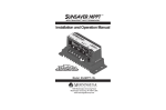
1.2 Network
A typical EtherNet/IP network forms several point-to-point connections. A typical
network in the factory would comprise of variety of complex devices such as HMIs,
PLCs, motion controllers, bar code scanners to simple devices such as I/O. This
configuration is represented in Figure 1-1.
Figure 1.1: EntherNet/IP Network Example
Ethernet/IP Programmer's Guide:
• 1-1 •
ACS Drive/Controller
1 : OVERVIEW
1.3 Definitions
The following definitions provide a general context for terms used in this guide in the
EtherNet/IP implementation
Device: A device is considered any product that supports the EtherNet/IP
encapsulation of CIP.
Connection: A connection is a logic link between two devices that may share more
than one connection.
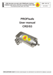
Scanner: A master or controlling device that initiates a request or connection.
Adapter: A device that receives a connection request or an individual service
request. Multiple adapters can be connected to one scanner on a network. The ACS
drive is an adapter device (see Figure 1-2).
(SCANNER)
(SCANNER)
PLC
HMI
(ADAPTER)
ACS
Figure 1-2: ACS Drive as an Adapter Device.
Assembly: A collection of pre-defined data that resides in an adapter. Each datapoint
is identified by its own unique instance number, size and type. There are three types
of assemblies: producing (data to be sent); consuming (data to be received); and
configuration (how the data is to be consumed and interpreted).
Explicit Messaging Connection: A connection used for individual request/
response transactions that are handled in the EtherNet/IP protocol via TCP.
For example, an explicit connection request from a scanner device results in a
response from the adapter device indicating a successful or failed request. If data
payload was part of the request, this information would also be included.
Requests from a scanner device is called a service request and these requests are
identified by one-byte service codes inside the request pocket. CIP specifications
define the meaning of the majority of these service codes however, codes 0x4B
through 0x63 have meanings specific to the destination object of the service request.
Ethernet/IP Programmer's Guide:
• 1-2 •
ACS Drive/Controller
1 : OVERVIEW
Service request destinations are defined by a portion of the request packet, or path
that is either an object description or an ASCII character string. The adapter device
receiving a service request distinguishes between an object description path ASCII
character string path by the path's header bytes.
Class (type of object reference), instance (object of the type), and the attribute
numbers inside the path identify a request to an object. For example, a mixed carton
of oatmeal contains 24 packages (objects) and are considered instances 1 through
24. Each object can have multiple attributes. In this example, the carton contains 6
different flavors or attributes 1 through 6. An example service request from a scanner
would be to ask for the flavor of package or object number 12. Explicit message
commands or data requests can also be sent from the scanner to individual target
nodes via connected or unconnected messages. A connected message establishes a
formal CIP connection between devices that allows each device to detect and report
either established or failed connections. Unconnected messages are managed by the
internal stack's Unconnected Message Manager (UCMM) and does not establish a
periodic explicit connection.
Implicit or I/O Connection: A connection that establishes a periodic exchange of
data between a scanner and adapter. A repetition packet interval or RPI (normally
expressed in milliseconds) is established by the scanner device in both directions.An
I/O connection request also establishes the size of each assembly and the instance
numbers of the assembly types (producing, consuming and configuration). To allow
the adapter to interpret subsequent data exchange, an I/O connection may also
contain data destined for the adapter's configuration assembly. In EtherNet/IP the I/O
connection itself is established via TCP but the subsequent exchange of data uses
UDP.
An I/O connection also determines how the adapter device should send its data,
either point-to-point (addressed to the scanner only) or multicast (address group that
includes the scanner), and allows other devices on the network to receive data from
the adapter. NOTE: If the data is sent via multicast, the adapter device itself must
support multicast or the connection will fail.
Both, explicit service requests and implicit I/O connections allow scanner access to
parameters, however the process differs. Typically, the scanner device utilizes HMI
or PLC software such as Allen Bradley's ControlLogix. PLC's normally will make both
explicit and I/O connections.
Ethernet/IP Programmer's Guide:
• 1-3 •
ACS Drive/Controller
1 : OVERVIEW
1.4 Layer Structure
Figure 1-3 below shows the seven layers of protocol implementation. Tolomatic's ACS
Drive user device profile resides on the seventh layer.
Figure 1-3: EtherNet/IP Layer Structure with the ACS Drive as the User Device Profile
1.5 References
{1} The CIP Network Library Volume 1: Common Industrieal Protocol, Edition 3.10,
April 2011
{2} The CIP Network Library Volume 2: EtherNet/IP Adaptation of CIP, Edition 1.11,
April 2011
Ethernet/IP Programmer's Guide:
• 1-4 •
ACS Drive/Controller
2
ACS EtherNet/IP Requirements
2.1 Definitions
ACS Drive & Controller Part Number 36049654 is the only part number with
EtherNet/IP capability. ACS drive part number can be found on the label on the
front cover.
2.2 Cabling
The selection of cable has a profound impact on network performance and
reliability. Selecting the correct cable requires an understanding of the environment
where the cable is installed.
Due to high data rate and reliability considerations, at the minimum, Cat5e cables
should be used with the ACS drive. If the cables are made on site, they must be
tested to meet performance criteria set according to TIA/EIA-568-B standard. This
cable definition is the general cable requirements for copper and fiber cabling
installations.
EtherNet/IP specifications limit the channel to 100 meters or up to 90 meters
horizontal wiring with two 5-meter patch cords. Some applications will require
longer patch cords. In these applications the total length of horizontal wiring
must be adjusted to compensate for the added loss of each connector pair and
additional patch cord length beyond 10m.
(102-H)
C = (1 + D) (1)
Where:
C is the maximum combined length (m) of the work area cable, equipment cable,
and patch cord.
H is the length (m) of the horizontal cable (H + C <= 100 m).
D is a de-rating factor for the patch cord type (0.2 for 24 AWG UTP/24 AWG ScTP
and 0.5 for 26 AWG ScTP). The derating factors are based on COMMERCIAL
cables. Other constructions, such as high flex, may have different performance.
Consult the manufacturer for information.
W is the maximum length (m) of the work area cable.
T is the total length of horizontal, patch and equipment cords.
The maximum stranded cable length is limited to 85mm for the channel with the
standard 20% derating for standard stranded cables.
Ethernet/IP Programmer's Guide:
• 2-1 •
ACS Drive/Controller
2 : ACS ETHERNET/IP REQUIREMENTS
WIRE TYPE VERSUS LENGTH
D
PATCH
CABLE
PATCH
GAUGE
DERATING
H
HORIZONTAL
LENGTH
(H+C<=100M)
W
PATCH
C
TOTAL LENGTH
LENGTH
PATCH AND
EQUIPMENT
T
TOTAL LENGTH
OF PATCH,
EQUIPMENT AND
#24
0.2
100
0
0
HORIZONTAL
100
#24
0.2
0
80
85
85
#24
0.2
25
59
64
89
#24
0.2
50
38
43
93
#26
0.5
0
63
68
68
#26
0.5
25
46
51
76
#26
0.5
50
30
35
85
#26
0.5
100
0
0
100
Table 2-1: Cable Wire Type Versus Cable Length
Please refer to Section 8-9.2.3.6 of the ODVA EtherNet/IP Standard v. 1.11 for
additional information.
2.3 Tolomatic Motion Interface (TMI) Requirement
The TMI is used to configure the ACS Drive including setting up the Ethernet port.
PC HARDWARE MINIMUM REQUIREMENT
Processor
1 GHz
RAM
512 MB
Disk Space
32-Bit 600 MB
Disk Space
64-Bit 1.5 GB
USB
1 USB Connection
USB to Serial Converter
1 USB to Serial Converter
Table 2-2: Hardware Requirements
The Tolomatic Motion Interface (TMI) is compatible with the following operating
systems: Windows® 7 and Windows® XP.
For all platforms, it is recommended that you upgrade to the latest Windows
Service Pack and critical updates from the Windows Update Web Site at http://
go.microsoft.com/fwlink/?LinkId=168461 to ensure the best compatibility and
security.
The TMI software is not supported on IA-64-based (Itanium) systems.
Ethernet/IP Programmer's Guide:
• 2-2 •
ACS Drive/Controller
2 : ACS ETHERNET/IP REQUIREMENTS
2.4 Firmware Requirements
Features described in this manual require Tolomatic ACS Drive firmware version
2.0.0.0 or higher.
2.5 EDS File
A EtherNet/IP Electronic Data Sheet (EDS) file is available for ACS Drives that
supports EtherNet/IP. Please download that from http://www.tolomatic.com
Ethernet/IP Programmer's Guide:
• 2-3 •
ACS Drive/Controller
ACS Drive Configuration Using TMI
3
ACS Drive Configuration for EtherNet/IP is a 2-step process:
1. Using Tolomatic Motion Interface (TMI), assign an IP Address, Subnet Mask and
Gateway.
2. Using TMI set the drive to EtherNet/IP mode.
For information related to setup, installation of Tolomatic Motion Interface, please
refer to TMI User Manual.
3.1 Setup IP Address
Choose the Tools -> Ethernet menu selection or press the Configure Ethernet button
in the toolstrip.
Figure 3-1: Ready to Manually Enter the IP Address
Enter the IP address, Subnet Mask and Default Gateway parameters for the
network. (The values shown above are the factory default values for the ACS drive.
Typically, at least the IP address and Default Gateway will need to be changed for
the network.)
To test the Ethernet settings, the Test button can be used to download the Ethernet
settings to the ACS drive and when the Test button is pressed, TMI will download
the settings to the ACS drive and initiate the PC to Ping the drive.
NOTE: An Ethernet cable must be connected from the PC to the ACS drive.
Ethernet/IP Programmer's Guide:
• 3-1 •
ACS Drive/Controller
3: A C S D R I V E C O N F I G U R A T I O N U S I N G T M I
Figure 3-2: A Manually Entered IP Address, Ready to Test
If the Test worked, a screen will pop-up showing similar results to the following.
Figure 3-3: Testing Verifies a Successful Ethernet Connection
If the Test didn’t work (in this example, the Ethernet cable was unplugged from the
ACS drive) an error dialog will be shown.
Figure 3-4: Testing Indicates a Failed Attempt for Ethernet Connection
Ethernet/IP Programmer's Guide:
• 3-2 •
ACS Drive/Controller
3: A C S D R I V E C O N F I G U R A T I O N U S I N G T M I
To configure the ACS drive for DHCP server in order to dynamically assign an IP
Address:
•check the “Obtain an IP address automatically” checkbox
•click OK on the ACS Internet Protocol (TCP/IP) Properties dialog
•click the Disconnect button on the TMI Drive tab (or press the Disconnect from
Drive button on the toolstrip)
•click Yes when asked “Update drive flash memory?”.
•cycle ACS drive power (turn off then turn on)
•press the Connect button on the TMI Drive tab (or press the Connect to Drive
button on the toolstrip)
When the Ethernet configuration tool is opened, the status bar informs the status of
the DHCP address configuration process. This is not dynamically updated. To see
the current status, press Cancel (or OK), wait a bit, then open this tool again.
Figure 3-5: Obtaining an IP Address Automatically
If there is a problem and the ACS drive is unable to get an IP address from the
DHCP server, the status bar will display the error message.
Ethernet/IP Programmer's Guide:
• 3-3 •
ACS Drive/Controller
3: A C S D R I V E C O N F I G U R A T I O N U S I N G T M I
Figure 3-6: Failed DHC Configuration
When Ethernet configuration is complete, press OK.
3.2 Configure EtherNet/IP Mode
Once ACS drive is correctly setup with IP address, mask and gateway, input
assemblies are available for scanner to consume. By putting ACS drive in EtherNet/
IP mode, ACS drive is ready to consume output assemblies from the scanner.
In TMI, go to the Mode Select tab and select the EtherNet/IP radio button as shown
here:
Figure 3-7: Selecting Operating Mode of ACS Drive
Ethernet/IP Programmer's Guide:
• 3-4 •
ACS Drive/Controller
3: A C S D R I V E C O N F I G U R A T I O N U S I N G T M I
Clicking on any other tab or navigating away from Mode Select tab will configure
the ACS drive for EtherNet/IP mode.
At this point, the ACS Drive is ready to be integrated with any scanner.
Ethernet/IP Programmer's Guide:
• 3-5 •
ACS Drive/Controller
EtherNet/IP & I/O Connections
4
The ACS drive will only allow two I/O connections. The ACS drive responds to
connection and service requests from a scanner and no commands or parameters
from the drive are required to allow these connections. However, certain commands
and parameters from the ACS drive, allow a user or program to monitor the status
and descriptions of the connections.
An implicit or I/O connection sets up the periodic exchange of data between the
ACS drive and the data tags in scanner memory. Configuration of the number
of parameters and which ones are used along with direction is set up at the
scanner—normally part of the PLC configuration process—and separate from the
PLC ladder programming.
An I/O messaging service request may result from a software driver implementation
(such as EIP Scan from Pyramid Systems), or may be part of a message box inside
a ladder rung of a PLC program. Service requests always contain a code (specifies
what is being requested) and a path (specifies destination object of request). The
paths of some of these service codes supported in the ACS drive, may take the
form of an ASCII character string or tag. Other paths will require specification of
class, instance and attribute.
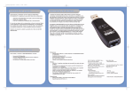
Input and output directions are from the perspective of scanner device. Input
assemblies are consumed by scanner devices and produced by adapter devices.
Output assemblies are produced by a scanner device and consumed by an adapter
device. Refer to Figure 4-1.
Output assemblies are commonly used for controlling the enable/disable state of
the drive and for supplying the velocity or position reference.
Input assemblies are commonly used to monitor the drive status and run-time
quantities such as current position and faults, if present.
Figure 4-1 EtherNet/IP I/O Assembly
4.1 Data Types
Data Types used in this Object Model are described in Table 4-1 below.
Ethernet/IP Programmer's Guide:
• 4-1 •
ACS Drive/Controller
4: E T H E R N E T / I P & I / O C O N N E C T I O N S
DATA TYPE
DESCRIPTION
USINT
Unsigned Short Integer (8-bit)
UINT
Unsigned Integer (16-bit)
UDINT
Unsigned Double Integer (32-bit)
SHORT STRINGnn
Character String (1st byte is length; up to nn characters)
WORD
Bit String (16-bits)
DWORD
Bit String (32-bits)
REAL
IEEE 32-bit Single Precision Floating Point
Table 4-1: Data Types
4.2 Input Assembly
.
INSTANCE
Input (T->0)
ATTRIBUTE ID
1
Instance 100
BYTES
0-3
TYPE
REAL
VALUE
Current Position
4-7
DWORD
Drive Status (32 bitmap statuses)
8-11
DWORD
Drive Faults (32 bitmap faults)
12-15
DWORD
Digital Input (8 bits used out of 32)
16-19
DWORD
Digital Output (4 bits used out of
32)
20-23
REAL
Analog Input
24-27
REAL
Analog Output
Table 4-2: ACS EtherNet/IP Input Assembly
ACS DRIVE STATUS
0
BIT
DESCRIPTION
Drive Enable: 0 = Not Enable; 1 = Enable
1
Drive Homed: 0 = Not Homed; 1 = Homed
2
Drive In Motion: 0 = Motion Complete; 1 = In
Motion
3
EStop: 0 = off; 1 = on
4
(internal use)
5
(internal use)
6
(internal use)
7
(internal use)
8
(internal use)
9
(internal use)
10-30
open
31
Drive Control: 0 = off (I/O, CTROFF), 1 = on
(Host, CTRON)
Table 4-3: ACS Drive Status
Ethernet/IP Programmer's Guide:
• 4-2 •
ACS Drive/Controller
4: E T H E R N E T / I P & I / O C O N N E C T I O N S
ACS DRIVE FAULTS
BIT
0
DESCRIPTION
Positive Limit
1
Negative Limit
2
E Stop
3
Position Error
4
Feedback Error
5
Overcurrent
6
Motor Overtemperature
7
Drive Overtemperature
8
Drive OverVolatage
9
Drive UnderVoltage
10
Flash Error
11-13
Open
Table 4-4: ACS Drive Faults
4.3 Output Assembly
INSTANCE
Input (0->T)
ATTRIBUTE ID
3
BYTES
0
TYPE
USINT
Instance 112
VALUE
Network Outputs
Bit 0: Enable
Bit 1: Start Motion
Bit 2: Home
Bit 3: E-Stop
Bit 4-7: Reserved
1
USINT
Move Select (0-16)
2-3
NA
Reserved
Table 4-5: ACS EtherNet/IP Output Assembly
Ethernet/IP Programmer's Guide:
• 4-3 •
ACS Drive/Controller
4: E T H E R N E T / I P & I / O C O N N E C T I O N S
INSTANCE
Output (O->T)
Instance 113
ATTRIBUTE ID
3
BYTES
0
TYPE
USINT
VALUE
Network Outputs
Bit 0: Enable
Bit 1: Start Motion
Bit 2: Home
Bit 3: E-Stop
Bit 4-7: Reserved
1
USINT
Move Select (0-16)
2-3
NA
4-7
REAL
Target 0 Position
8-11
REAL
Target 0 Velocity
12-15
REAL
Target 0 Acceleration
16-19
REAL
Target 0 Deceleration
20-23
REAL
Target 0 Force
24-27
DWORD
Target 0 Motion Type
(absoute or incremental)
28-31
DWORD
Digital Output (4 bits
used out of 32)
Reserved
Table 4-6: ACS EtherNet/IP Full Output Assembly
Ethernet/IP Programmer's Guide:
• 4-4 •
ACS Drive/Controller
Explicit Messaging
5
One of the explicit message objects is allocated as part of the predefined slave/
adapter connection set as defined in the Ethernet/IP specification.
The other may be allocated using the Unconnected Message Manager (UCMM)
protocol.
These objects can be used to access any ACS Drive parameter.
OBJECT ID
1
OBJECT NAME
Vendor Identity
PURPOSE
Identifies the drive as ACS Drive & Controller
Assembly
ACS Drive currently supports two (2) Output assembly
objects and one (1) Input assembly object as specified by
EtherNet/IP standard
245
TCP
ACS Drive TCP/IP Interface Object provides information
about TCP/IP network interface such as IP Address,
Network Mask, Gateway, Host Name
246
Ethernet Link
ACS Drive Ethernet Link Object provides information about
Speed and Duplex connection
4
Table 5-1: Message Objects
5.1 Identity Object
The following tables contain the attribute, status, and common services information
for the Identity Object.
INSTANCE
ATTRIBUTE
Class (Instance 0)
ID
1
Instance 1
NAME
CIP DATA
DATA VALUE
Revision
TYPE
UINT
1
1
Vendor number
UINT
1230
2
Device type
UINT
0
3
Product code number
UINT
9046
4
Product major revision
USINT
01
Product minor revision
USINT
01
5
6
Status
Serial number
WORD
UDINT
7
Product name
SHORT
STRING32
NA
Unique 32
bit value
ACS Drive &
Controller
Table 5-2: Identity Object (01HEX - 1 Instance)
Ethernet/IP Programmer's Guide:
• 5-1 •
ACS Drive/Controller
5: E X P L I C I T M E S S A G I N G
Identity Object Common Services
SERVICE CODE
IMPELEMENTED FOR
CLASS LEVEL
INSTANCE LEVEL
SERVICE NAME
01Hex
No
Yes
Get_Attribute_All
05Hex
No
Yes
Reset
0EHex
Yes
Yes
Get_Attribute_Single
10Hex
No
Yes
Set_Attribute_Single
Table 5-3: Identity Objects Common Services
5.2 Assembly Object
The following tables contain the attribute, instance, data mapping, and common
services information for the Assembly Object.
INSTANCE
Class (Instance 0)
Input
ATTRIBUTE ID
1
NAME
Revision
CIP DATA TYPE
UINT
DATA VALUE
2
2
Max instance
UINT
129
3
(T->0)
Refer to Table 4-2
(Instance 100)
Output
3
(0->T)
Refer to Table 4-5
(Instance 112)
Output
3
(0->T)
Refer to Table 4-6
(Instance 113)
1
254 (0xFE)
4
Input only
heartbeat1
Heartbeat
0
255 (0xFF)
5
Listen only
heartbeat2
Heartbeat
0
253 (0xFD)
6
Output Only
heartbeat3
Heartbeat
0
This instance allows clients (PLCs) to monitor input data without providing output data.
This instance allows clients (PLCs) to monitor input data without providing output data. To use this
connection type, an owning connection must exist from a second client and the configuration of the
connection must match exactly.
2
3
This instance allows output data without providing input data.
Table 5-4: Assembly Object (04HEX . 6 Instances)
Ethernet/IP Programmer's Guide:
• 5-2 •
ACS Drive/Controller
5: E X P L I C I T M E S S A G I N G
Assembly Object Common Services
SERVICE CODE
IMPELEMENTED FOR
CLASS LEVEL
INSTANCE LEVEL
SERVICE NAME
E HEX
Yes
Yes
Get_Attribute_Single
10HEX
No
Yes
Set_Attribute_Single
Table 5-5: Assembly Objects Common Services
5.3 TCP/IP Object
Please refer to Volume 2: EtherNet/IP Adaptation of CIP v. 1.11, 5-5.3 for exact
format and interpretation of attributes.
INSTANCE
Class (Instance 0)
Instance 1
ATTRIBUTE ID
1
NAME
DATA TYPE
Revision
UINT
1
Status
DWORD
2
Configuration capability
DWORD
3
Configuration control
DWORD
4
Physical Link Object
Structure of
Path size
Path
5
UINT
Array of Word
Interface configuration
Structure of
IP Address
Network MasK
Gateway Address
Name Server
Name Server 2
Domain Name Size
Domain Name
6
UDINT
UDINT
UDINT
UDINT
UDINT
UINT
STRING
Host name
Structure of
Host Name Size
Host Name
UINT
STRING
Table 5-6: TCP/IP Object (0xF5HEX - 1 Instance)
TCP/IP Object Common Services
SERVICE CODE
IMPELEMENTED FOR
CLASS LEVEL
INSTANCE LEVEL
SERVICE NAME
E HEX
Yes
Yes
Get_Attribute_Single
10HEX
No
Yes
Set_Attribute_Single
Table 5-7: TCP/IP Object Common Services
Ethernet/IP Programmer's Guide:
• 5-3 •
ACS Drive/Controller
5: E X P L I C I T M E S S A G I N G
5.4 Ethernet Link Object
Please refer to Volume 2: EtherNet/IP Adaptation of CIP v. 1.11, Section 5-5.4 for
exact format and interpretation of attributes.
INSTANCE
Class (Instance 0)
ATTRIBUTE ID
1
NAME
Revision
UINT
1
Interface speed
UDINT
2
Interface flags
DWORD
3
Physical address
USINT Array (6)
Instance 1
DATA TYPE
Table 5-8: Ethernet Link Object (0xF6HEX - 1 Instance)
Ethernet Link Object Common Services
SERVICE CODE
IMPELEMENTED FOR
CLASS LEVEL
INSTANCE LEVEL
SERVICE NAME
E HEX
Yes
Yes
Get_Attribute_Single
10HEX
No
Yes
Set_Attribute_Single
Table 5-9: TCP/IP Object Common Services
Ethernet/IP Programmer's Guide:
• 5-4 •
ACS Drive/Controller
Appendix
Troubleshooting
SYMPTOM/TROUBLE
No Ethernet Communication
POSSIBLE CAUSE/RESOLUTION
1. Check Ethernet Cable.
2. Verify Ethernet Cable is plugged in securely.
3. Incorrect combination of IP Address, Subnet Mask, Gateway. Check
with your network administrator to determine correct combination.
4. Try different Ethernet port on the drive.
No EtherNet/IP connectivity
1. Check your assembly configuration.
2. Check if Ethernet communication can be established with the drive
using PING utility.
3. Check if Digital Outputs can be set/reset using EtherNet/IP O->T
assembly.
4. Advanced Troubleshooting Tip: Check Ethernet packets received and
sent to the PLC from and to the drive.
Motion cannot be executed over
EtherNet/IP
1. Check if Drive Status, Drive Faults, Digital Inputs and Outputs can
be queried over EtherNet/IP. If drive is not sending them, then
troubleshoot Ethernet communication.
2. Check if drive is configured with EtherNet/IP communication mode
using Tolomatic Motion Interface Software.
3. Check if Digital Outputs can be set/reset using EtherNet/IP O->T
assembly. If the Digital Outputs of the drive cannot be set or reset
using EtherNet/IP O->T assembly then troubleshoot the Ethernet
communication.
4. Advanced Troubleshooting Tip: Try different EtherNet/IP scanner to
interface with Tolomatic ACS Drive.
Ethernet/IP Programmer's Guide:
• A-1 •
ACS Drive/Controller
Copyright © 2011 Tolomatic, Inc. All rights Reserved.
All brand and product names are trademarks of their respective
owners. Information in this document is believed to be accurate at
time of publication.
201110121047
3800 County Road 116, Hamel, MN 55340
Phone: 763.478.8000
Toll Free: 1.800.328.2174
Fax: 763.478.8080
Email: [email protected]
www.tolomatic.com