1
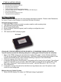
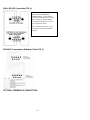
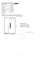
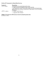
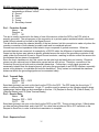
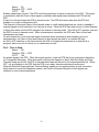
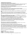
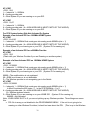
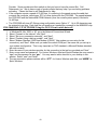
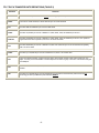
TABLE OF CONTENTS
Overview
CDS-9060 Description
What is CDMA?
How the technology works
CDMA network providers in North America
Equipment manufacturers
Data deployment and services
Data Capabilities
Wireless Data Modems
Safety Precautions for the User
CDS-9060 Features
Standard features
Optional features
CDS-9060 layout (Fig. 1)
Connector assignments
LED Functions
System current requirements
Specifications
Getting Started
Standard package contents
Cellular / PCS data service setup or digital / PCS modem / phone activation
Before calling the cellular provider
What to ask the cellular provider
What to tell the cellular provider
Connecting to the CDS-9060 and local configuration menu programming
Configuration examples
Programming the phone number
Dialing into the CDS-9060 programming menu
Setup for local or remote dialing (Fig. 2)
Displaying signal strength
Local and remote COM PORT baud rate setup
Programming alarm (cry-out) SMS, E-Mail, Input/Output and Data
Exiting from the configuration menu
Custom Optional Features
CDS-9060 modem initial string setup
Customizing Modem Init string
Auto answer mode setup
Setting up Dial-Up Network 1XRTT
Clock and Receive Windows Setup
Why set up windows?
Programming the clock
Start/Stop time windows setup
Sample start/stop configuration menus
3
3
4
4
5
5
5
5
6
6
7
7
7
8
8
8
8
9
10
10
10
10
10
11
11
11
12
12
13
13
13
15
15
15
15
15
17
17
18
18
18
19
19
Remote Programming
Remote programming of cellular phone number
Reprogramming Telephone Information Programming Menu
Changing mobile phone number (A)
Changing MSID (B)
Changing CDMA and AMPS System ID (C & D)
Changing Slot Cycle Index (E)
Changing Preferred Mode (F)
Changing Preferred Service (G)
Changing PRL enable (H)
Changing Dial *18 every 4 hours (I)
Dumb Mode
SMS for the CDS-9060 Series
SMS Symbols
“Forced” SMS Messaging/Cry Out Alarms
Alarm Cry Out
RS-232 setup
CDS-9060 DB-9 female to terminal block (Fig. 3)
3-wire RS-232 connections (Fig. 4)
CDS-9060 programming and modem cable (Fig. 5)
CDS-9060 DB-9 male to DB-25 female (Fig. 6)
CDS-9060 terminal block to DB-25 female (Fig. 7)
Host PC modem setup
Generic AT strings
Host modem manufacturers
Commands reference
Introduction to commands
CDS-9060 cellular and PCS CDMA AT-commands
Qualcomm proprietary commands
Basic AT parameters
S-registers
Basic action commands
CDMA AT parameter commands
Cellular AT commands for packet data services
CDMA AT command for DTE devices that will not handle packet data
RS-232 characteristics
RS-232 signals functional description
Signal travel direction
Electrical signal characteristics
Troubleshooting tips and FAQ’s
CDS-9060 IS95 Dial-up Network Circuit Switch Data Call
ITU-T Data Transfer Rate Definitions
Glossary of Wireless Terms
20
20
20
20
20
20
21
21
21
21
21
21
21
23
24
24
25
25
26
26
26
27
27
28
28
29
29
30
30
31
31
32
33
34
34
35
35
37
37
38
40
41
42
NOTICE:
Because of the nature of wireless communications, transmission and reception of data can never be
guaranteed. Data may be delayed, corrupted (i.e., have errors) or be totally lost. Although significant
delays or losses of data are rare when wireless devices such as the DataRemote modem are used in a
normal manner with a well-constructed network, the DataRemote modem should not be used in situations
where failure to transmit or receive data could result in damage of any kind to the user or any other party,
including but not limited to personal injury, death, or loss of property. DataRemote, Inc., accepts no
responsibility for damages of any kind resulting from delays or errors in data transmitted or received using
the DataRemote modem, or for failure of the DataRemote modem to transmit or receive such data.
OVERVIEW
This documentation describes the features, functions and the interfacing of the CDS-9060 products, to
other DTE (Data Terminal Equipment) devices. This manual was written for people who have a basic
understanding of DCE (Data Communications Equipment) and DTE products. Refer to the glossary for
terms used in this User Guide.
CDS-9060 DESCRIPTION
The CDS-9060 is a cost-effective, self-contained Cellular/PCS (Personal Communication Services) system
for remote telemetry, meter reading, data communication and the basic building block for the CDS-9060
AVL (Automatic Vehicle Location) modem. The CDS-9060 is a complete digital cellular or PCS standalone
modem. It operates at 800 or 1900MHz CDMA, with the option of Analog AMP’s fallback, (Model CDS9060A) to a standard analog cellular connection. The CDS-9060 series is designed to communicate with a
throughput of 300 bps to a maximum of 115,200bps.
The CDS-9060 DCE functions just like a standard landline modem and is compatible with 95 percent of the
host modems on the market today, since it uses IS-95A, IS-95B, IS-707, IS-683, SMS and 1XRTT
(CDMA2000) CDMA (Code Division Multiple Access) data and voice standards. Using CDMA for remote
wireless data retrieval applications, one will experience a much more reliable connection rate than using an
analog circuit switch at faster download speeds.
The CDS-9060 is much more than just a standalone wireless modem. Integrated menu features permit
configuring the unit locally or remotely. Its four programmable windows permit turning the unit off to
conserve power at specified times of day. With the step-by-step menu embedded in the firmware,
programming the phone\radio, and various other options can be accomplished without assistance from the
cellular provider.
The CDS-9060 is a CDMA only unit with 12 logic inputs and outputs, the CDS-9060A has added features
including an analog cellular modem. The CDS-9060G series has the addition of a GPS (Global Positioning
System) module along with a second RS-232 port, and 512kb of memory for data logging. Since
approximately 97 percent of the United States is covered by either CDMA or analog cellular, the CDS-9060
series ensures coverage in most areas.
Analog or memory/RS-232 port upgrade modules can be purchased at a later date if needed, or you can
send your unit to DataRemote to get upgraded at any time for a nominal charge. If the CDMA coverage
does not adequately cover the area in which the CDS-9060 will be used, you should order the CDS-9060A
3
tri-mode CDMA/analog modem, order the analog upgrade module, or send the CDS-9060 for an upgrade.
The analog feature enables the CDS-9060A to operate in either analog or digital mode, at the same low
rates as digital service, with most wireless providers. (Check with your wireless provider for rate
structure)
For GPS-AVL applications, the CDS-9060AG provides nationwide coverage. This unit includes a CDMA
modem, GPS engine and DRI DRIP Controller, with 512kb of memory for downloading and archiving data,
as well as an analog modem module for tracking vehicles anywhere and at anytime, and is compatible with
most tracking software. You can program up to 50 events that are trigger by Time & Distance, Input
closure, fencing and much more, application notes.
What is CDMA?
CDMA, or Code Division Multiple Access, is a digital alternative to the analog AMPS (Advanced Mobile
Phone System). Qualcomm®, Inc. introduced CDMA three months after TDMA was accepted as a
standard. After two years of testing CDMA was finally accepted as a second standard. CDMA works under
a principle that has been used in military satellites for decades. Each conversation is granted a certain
code. Many conversations can be sent over the same spectrum at the same time with the receiving units
decoding which information is directed to them. This is often compared to discerning a conversation in
one's native language in a jumble of conversations in other languages. CDMA allows 4.4 trillion of these
codes, assuring that many different callers on different systems can use the same spectrum at the same
time. CDMA utilizes spread-spectrum technology, meaning that conversations are spread across wide
segments of the cellular broadcast spectrum. This helps avoid problems in busy areas and in hilly areas
where reflected signals can cause problems.
Spread spectrum technology is also the means by which codes can be attached to the communication.
Each bit is expanded into some number of "chips”. Thus, data transmission requires much more
bandwidth, requiring much of the available spectrum. However, many conversations can be transmitted
over the same spectrum. The transmitter multiplies each bit by a "key" and transmits the multi-chip result.
The receiver receives these chips as well as those of all other conversations transmitted over the
spectrum. The receiver multiplies this combined signal by the appropriate key, takes the sum, and is able
to determine which bit is appropriate. Because different signals can be transmitted over the same
spectrum, CDMA allows 10 to 20 times as many conversations to occur on a system than AMPS. CDMA
technology nearly eliminates many common cellular problems related to overcrowding, such as busy
signals, dropped calls, and cross talk. Also, CDMA's voice encoding allows for the reduction of
background noise. CDMA transmission occurs at power levels 1/25 to 1/1000 those of AMPS or TDMA.
This allows lighter portable phones with longer battery life. CDMA's digital control channel allows the
demands for mobile fax, data transmission, and caller-ID as well.
How the Technology Works
Introduction
CDMA is one of three 2nd generation cellular network technologies: CDMA, TDMA and GSM.
•
GSM uses 200 KHz channels divided into eight time slots. A single handset uses one slot in two
channels for sending and receiving.
•
TDMA standard IS-136 uses 30 KHz channels, with each channel divided into six time slots. A
single handset uses one time slot for sending and the other for receiving.
•
CDMA uses 1.25 MHz signal bands that are shared simultaneously by all users. Power control is of
paramount importance to CDMA, rather than the management of alternating time slots.
4
CDMA is available for both the cellular (800 MHz) and the PCS (Personal Communications Services) (1900
MHz) frequency bands in North America. Measured by cellular subscribers, analysts report that CDMA
has the fastest percentage growth rate. Today, there are more than 110 million CDMA subscribers
worldwide. CDMA has long term potential to change the direction of telecommunications. It is conveniently
similar to the way in which data networking functions. CDMA is paving the way for the telecom industry to
move toward a model in which data plays a much more significant role.
CDMA Network Providers in North America
Verizon Wireless®
•
Operates the largest of all digital networks
•
Serves a majority of cities and communities in the US
•
Provides service in all 50 states
•
Approximately 24 million customers today
•
Operates at both 800MHz and 1900MHz
Sprint Wireless®
•
Operates at 1900MHz
•
Serves over 8,000 cities and communities in the US
•
Provides service in all 50 states
•
Approximately 18 million customers today
Alltel Wireless®
•
Operates at 800MHz CDMA and 800MHz Analog
•
Serves over 1,500 cities and communities in the US
Equipment Manufacturers
Qualcomm® pioneered the development of CDMA technology, and holds many of the essential patents
needed to build CDMA based devices. Infrastructure equipment manufacturers that provide CDMA
systems include Nortel Networks®, Lucent®, Motorola®, and Ericsson® (through its acquisition of
Qualcomm's infrastructure business).
Data Deployment and Services
The CDMA specifications provide for both voice and data capabilities. To date, however, the primary focus
of infrastructure equipment manufacturers and service providers deploying CDMA has been to deploy
voice services to improve capacity and quality for their voice subscribers. A full roll out of data deployment
momentum and service availability is expected to increase significantly.
Data Capabilities
CDMA specifications provide for three types of data services: short message service (SMS), circuit
switched data, and packet switched data. SMS provides two-way pager-like functionality, allowing short
text messages to be sent, received, and acknowledged. Circuit-switched data allows dialup modem
5
connections over the cellular network. Circuit-switched support will initially be available at speeds up to
14.4 Kbps. Packet-switched data will provide Internet Protocol connectivity, at speeds of 166 Kbps. As of
September 1, 2001 the providers are using circuit switch data for CDMA connectivity and the Analog side
of the System for Analog data. Qualcomm® states that IS-95B is backwards compliant for packet data
protocol (1XRTT). In other parts of the world, including Japan, Korea, China, Australia, New Zealand, and
some parts of South America, CDMA networks have been deployed. Today, these networks use the IS95A / IS-95B protocols and CDMA2000.
Wireless Data Modems
Dataremote, Inc wireless data modems will support circuit-switched data and packet-switched data as well
as SMS messaging. Packet-switched connectivity will appear LAN-like: always on, always connected.
Mobile and remote data communications, including Internet and intranet access, are the primary
applications of wireless data modems, while voice capabilities may add some secondary utility. For more
information on CDMA, visit the CDMA Development Group website at www.cdg.org
SAFETY PRECAUTIONS FOR THE USER
The following notes are for OEM’s who incorporate the CDS-9060 series modem and applications based
on the CDS-9060 modem into their final product. These safety precautions must be incorporated into the
instruction manual supplied to the end user.
Electrical Safety
The lowest input voltage that can be applied to the CDS-9060 is 10.5 VDC; the highest voltage that can be
applied is 18 VDC.
Aircraft Safety
Cellular modems can interfere with an aircraft's navigation system. Use of CDS-9060 modem on board an
aircraft is forbidden by federal law.
Electronics in Medical Equipment
Radio transmitters, including cellular phones, can interfere with the operation of inadequately protected
medical devices. Address all questions to a physician or to the manufacturer of the medical device.
Precautions in the Event of Loss/Theft of the CDS-9060
If the CDS-9060 Modem is missing, notify the cellular network operator immediately in order to prevent
misuse.
6
CDS-9060 Standard Features
• Standard DB-9 female, RS-232C interface (DCE)
• RS-232 modem block DCE connector for wire attachment
• Auto answer/auto dial
• Real time clock (supports polling)
• User-programmable on site
• 12 control inputs and outputs
• Call progress monitor for trouble-free cellular calls
• Cellular/PCS network monitoring
• Polling windows to reduce power consumption
• Remote DCE COM settings (baud rate)
• Antenna connector: TNC style 50 Ohm female
• Hayes AT-Commands
• Reboots automatically if a problem is detected
• Remotely programmable (windows, alarm number, AT-String, NAM/phone number, baud rate and real
time clock)
• 12 - 32VDC input voltage range
• Low voltage shutoff (Shuts down if voltage drops to 9.3 VDC; turns back on when voltage reaches
• 12 VDC.) Note: this feature is for solar/battery and telemetry applications to prevent full discharge of
battery.
• SMS via AT-Commands
• TCP/PPP/UDP/POP-3 Stack
Optional Features
• Analog modem module
• GPS module
• Second RS-232 port with 512kb and DRIP protocol
• Programming of I/O ports
• Antennas for various applications
• Solar panel systems
• NEMA-4x (all-weather) enclosure
• 12 VDC power supplies
• Host modems, cellular ready
7
CDS-9060 Layout (Fig. 1)
P3 Connections
1 - +12 VDC nominal
2 - power supply GND
3 - ignition switch
DTR
GND
ANTENNA
50 Ohm TNC
CD
TX
RX
P/S
AUDIO
JACK
SMA
12 VDC
Current Requirements
AUX
5 VDC GPS
ANTENNA INPUT
Transmit (worst case) idle sleep mode
CDS-9060 =
800 mA
53 mA
1.2mA
CDS-9060A =
1.5 A
53 mA
1.2mA
CDS-9060 AG= 2.0 A
105 mA
1.2mA
IGNITION
P2 Connections
I/O Port
DCE COM 1
DCE COM 2
Connector Assignments
P1 – RS-232 DB-9 female standard DCE port,
(use any straight through\modem cable).
P2 - Cry-out alarm activation input, voice dial input, Data call
input and SMS or alarm input.
P3 - Input power connector, 12 to 32VDC w/ignition switch
P4 & P5 - Analog Modem option header
P6 – Bus connection to radio module
9029 adapter pcb – 8 pos Phoenix terminal block Optional
LED Functions
D1 – Data Terminal Ready (DTR)
D2 – Carrier Detect (CD)
D3 – Transmit Data (TXD)
D4 – Receive Data (RXD)
D5 – Power/Status Indicates mode: digital, analog, or no
signal:
• 1 blink/sec= CDMA mode with CDMA data available
• 3 blinks/sec= Analog mode only
• long blink (500ms) = No service detected
D6 – Operational mode: Forced analog/Aux.
9060 PCB Connections
1 – Signal Ground
2 – TXD (transmit)
3 – RXD (receive)
4 – RTS (ready to send)
5 – CTS (clear to send) 6 – DSR (data set ready)
7 – DTR (data terminal ready)
8 – CD (carrier detect)
8
station header for cry-out alarm and Digital inputs and
outputs outbound data call input (circuit 1), outbound voice
dial input (circuit 2), SMS/alarm input (circuit 3), and other
programmable I/O. See Pg. 41 (CDS9026 I/O Schematic)
•
•
Modem I/O to DTE device
Programming input, Etc.
CDS-9060 SPECIFICATIONS, AVAILABLE OPTIONS AND APPLICATIONS
GENERAL SPECIFICATIONS
Power Requirements:
On-Board Backup:
Serial I/O:
Control I/O:
Command Protocol:
LED Indicators:
12-32VDC @ 2A (unregulated)
3.6V 200MA (CR2032) Lithium Cell
RS-232, Async, 2 DB-9 and 1 - 8 pos. terminal block Connectors
16 Pos. IDC compatible header
AT Command Set and DataRemote, Inc (DRI) Configuration Menu
Power ON, Status, TXD, RXD, DCD, DTR, AUX
Modem:
IS-707A compatible, IS-95A/B (MDR verified on IS-95A/B networks)
AMPS modem (Conexant Chipset V.32B)
8 Kbps CELP, 13 Kbps QCELP, 8 Kbps EVRC
QVFQCP-2235
3572A11989
Vocorder:
FCC ID:
Canada ID:
RF SPECIFICATIONS
Interface Standards:
800 MHz
1900 MHz (CDMA)
AMPS: ANSI/TIA/EAI-553
J-STD-008
CDMA: TIA/EIA, IS-95A/B
Operating Frequencies:
TX: 824-849 MHz
TX: 1850-1910 MHz
RX: 869-894 MHz
RX: 1930-1990 MHz
RF Power:
AMPS: 600mW (EIRP Nom.)
400mW (EIRP Nom.)
CDMA: 600mW (EIRP Nom.)
Maximum TX Power:
AMPS: +26.7dBm Min.
+23dBm Min.
CDMA: +23dBm Min.
Receiver Sensitivity:
AMPS: >116dBm @ 12dB Sinad
>104 dBm @ .05% FER
CDMA: >-104dBm @ 0.5% FER
Frequency Stability:
< ± 2.5 PPM
< ± 2.5 PPM
Antenna Interface:
50 ohm, TNC
50 ohm, TNC
Current
Can Very from Network to Network Normal current draw = 53ma
PHYSICAL SPECIFICATIONS
Size:
6.3"L X 4"W X 1.2" H
Weight:
23.0 Oz.
ENVIRONMENTAL SPECIFICATIONS
Temperature:
Operating: -30° C to +60° C (-22° to 140°)
Storage: -40° C to +70° C (-40° to 146°)
Humidity:
0-95% (non-condensing) 95° F (35° C)
STANDARD FEATURES
Authentication (CDMA)
CDMA 2000 1X RTT
Authentication analog AMPS cellular
IS-95 Circuit Switch
Preferred Roaming List
IS-707A service SMS commands
SMS via AT-Commands
TCP/PPP/UDP/SMTP Stack
Update PRL while unit is in the field
DRI Config menu remotely or locally programmable
Inputs for cry-out alarms “3 inputs, 3 DRIP inputs
and 6 DRIP outputs
• Voice Communications
• Analog Modem MNP-10EC and TX-Cell error
correction, V.22 to V.32Bis
• Switches from CDMA mode to analog automatically
•
•
•
•
•
•
•
•
•
•
•
9
TYPICAL APPLICATIONS
•
•
•
•
•
•
•
•
•
Automatic meter reading
Security system monitoring via RS-232
Slow-speed video applications
Heavy equipment monitoring
Traffic metering and programming highway displays
Connects to RTU’s, PLC’s, Dataloggers, etc. through a DTE RS-232 port
Flood control monitoring
Remote equipment sensing and control
Telematics and AVL Applications
GETTING STARTED
Inspect shipment for damage and to be sure package was shipped complete. Please contact Dataremote,
Inc. within 15 days for any damage or components that may be missing.
Standard Package Contents
1. CDS-9060 CDMA modem (mounted in powder-coated box with mounting holes)
2. TNC dual band mag mount antenna
3. RS-232 programming cable
4. Modem software (Terminal Program) used for setting up configuration menu
5. User manual
6. PRL loader and DRIP software program
CDS-9060G
CELLULAR / PCS DATA SERVICE SETUP OR DIGITAL / PCS MODEM / PHONE ACTIVATION
You will need to ascertain the following data prior to calling your Cellular Provider for activation:
1. Name of the CDMA carrier in the area where the modem will be used. Verizon Wireless and Sprint
PCS are the two largest CDMA carriers/providers. Both have CDMA and analog technologies on their
systems and between the two, have coverage exceeding 97 percent of the United States.
2. Identify the frequency band of the chosen carrier.
3.
Locate the ESN (Electronic Serial Number). This numbers will be found on the unit label. You will need
to give this information to your provider. Each CDS modem is equip with its own unique ESN. CDS9060 uses a Qualcomm® radio module built by Kyocera®, with the ESN prefix of 159, 179 or 254.
4. Area code desired.
5. Local prefix, to ensure that calls will not be billed at a long distance rate, even if the phone is used
outside the local calling area.
What to Ask your Cellular Provider
1. What is the SID (System ID) number for CDMA and Analog (if applicable)?
10
2.
3.
4.
What is the system Select or preferred service? The choices being Automatic, A auto, B auto, A only,
B only, and no roaming.
If you intend to use a pre-paid or calling card account, check with your provider to see if you will have
access to “Data Only” capability, as it is required.
Note: DataRemote will need to load a PRL file (Preferred Roaming List) in the Modem. DataRemote
does have PRL files for most major U.S. wireless providers. If you are going to be roaming, and
DataRemote does not have the carriers PRL file, it’s a good idea to ask your provider for their PRL file.
Be sure to ask DataRemote to load the desired Wireless Carrier PRL file when ordering.
What to tell your Cellular Provider NOT to Activate!
1. No voice mail
2. No caller I.D.
3. No three-way calling
CONNECTING TO THE CDS-9060 AND LOCAL CONFIGURATION MENU PROGRAMMING
1. Plug power into P3 (12 VDC nominal. See Fig. 1, p. 9)
2. On initial power up, the CDS-9060 LED’s will blink.
3. The CDS-9060 has completed the boot-up procedure (approximately 20-30 seconds) when the DTR (if
DTR is active) LED is on, the blinking PWR/Status LED is flashing,
4. Turn on your computer or laptop.
5. Connect the DB-9 RS-232 cable to your computer or laptop.
6. Launch a terminal program. (Supplied terminal program or use HyperTerminal, ProComm, etc.)
7. Select the correct COM port in software (COM 1 in most settings).
8. Set baud rate to 19200 bps (default for CDS-9060 series). Note: if setting is changed, DTE must be set
to same baud rate speed as the previous configuration of the CDS-9060.
9. Press CTRL-W three times quickly. (Hold down Control key and press W three times within two
seconds.)
10. The Configuration Menu will display. To check for proper communication between the CDS-9060 and
your host computer, type ATI3. You should see “ERROR” on the host display. If there is no response,
check that the DTR LED is illuminated verifying that you are connected to the correct COM port on the
host.
11. If menu still doesn’t come up or you can’t type AT enter go back to step 6.
Note: Do not remove primary power while in the programming menu.
*********** CONFIGURATION MENU - 1X-M ***********
A - Set Receive Window 1 13:30 to 13:50
B - Set Receive Window 2 14:10 to 16:00
C - Set Receive Window 3 16:20 to 23:00
D - Set Receive Window 4 08:30 to 13:00
E - Set Time:
08:27:08
F - Reprogram Telephone Information
G - Display Signal Strength
H - Remote Comms Baud Rate: 19200
I - Reprogram Alarm Information
J - Modem Init:
K - Auto Answer Mode: ON
L - Max call Time: 20
M - AUX processor Mode: DrIP:SMS
X - Exit to Terminal Mode
Battery voltage: 14.8 Phone #: 805-339-9739 CDMA SID: 2
11
Programming the Phone Number
1. Set-up your CDS-9060 as previously described.
2. When the Configuration Menu displays, select Option “F”, Reprogram Telephone Information.
3. The Programming menu will now display. (see below)
4. Select option “A”, Mobile Phone Number and press enter.
5. Enter the phone number including area code and press enter.
6. Select option “K” to program the phone.
7. Answer, “yes” to “Are you sure”.
It will prompt you to wait for 40 seconds, after unit reboots use CTRL-W to get back into main menu.
Assure that Auto Answer Mode, option “K”, in the Configuration Menu is turned “ON” before proceeding or the
CDS-9060 will not answer when called in the next section.
Example: Programming Menu
************** PROGRAMMING MENU *************
Equipment Serial Number : 25407720311
Preferred Roaming List # : 50085
A - Mobile Phone Number : 8053399739
B - MIN Number
: 8053399739
C - CDMA System ID
: 2
D - AMPS System ID
: 2
E - Slot Cycle Index
: 2
F - Preferred Mode
: Digital only
G - Preferred Service
: B auto
H - PRL enable
: ON
I - Dial *18 every 4 hours : OFF
J - Dumb Modem Mode
: OFF
K - Program Phone
L - Return to Main Menu
X - Exit to Terminal Mode
Dialing Into the CDS-9060 Programming Menu
Note: Before dialing into the CDS-9060 programming menu, a phone number and valid system I.D. number
must be programmed into the unit and your wireless provider must activate the modem.
1. Launch a Terminal Program from your host computer connected to a Hayes compatible modem.
2. Set up the terminal program to dial the CDS-9060. Set the baud rate (19,200bps default), COM port,
parity (None), and flow control (8,1).
3. Type AT into the terminal software.
4. The modem will respond OK.
5. Clear the buffer in host modem before dialing “AT&F”
6. To dial into the CDS-9060, use the standard ATDT command. (ATDTXXXXXXX)
“See trouble shooting for extended AT Commands”
7. After the CONNECT message displays or CD goes high; enter CTRL-W three times.
8. Main configuration menu will display.
10. Choose an Option or press Option “X” to exit the menu and go back to your DTE device.
Notes: While in the configuration menu, you can hit return key at any time to return to the previous page, or
enter “X” to exit the Configuration Menu.
b. Options that are changed in the Programming Menu while on-line will take effect after the
call is terminated.
12
COM Port Setting
Baud Rate
Parity and stop bits
Displaying Signal Strength
For local or remote connections, follow the steps below:
1. Enter configuration menu locally or remotely. (See above)
2. Press Option G.
3. After a few seconds, signal strength will display on the screen. (Example: Channel #, RSSI, Time. The
first reading is the channel. The maximum signal strength “RSSI” reading is 63. Signal strength of 31 or
higher is functional. If the signal strength is lower than 27 unreliable communications and dropped calls
may result. An optional Dataremote high gain antenna may be installed to increase the received signal
strength. Visit www.dataremote.com to view antenna options.
Example of RSSI
CDS-9026, Rev 4.0xx 07/17/03
Copyright 2000,1,2,3 Dataremote, Inc.
Received Signal Strength Indicator (RSSI)
No signal=0, Maximum signal=63
Channel,RSSI: 248,46 23:28:18
Channel,RSSI: 248,42 23:28:19
Channel,RSSI: 248,42 23:28:20
Channel,RSSI: 248,42 23:28:21
Channel,RSSI: 268,40 23:28:22 (Press any key to exit)
Local COM PORT Baud Rate Setup: START HERE
1. Enter configuration menu locally or remotely.
2. Press Option H.
13
The CDS-9060 DCE speed is defaulted to 19,200 bps; therefore the (CDS-9060) DCE speed must be
matched to the DTE speed (same as computers COM-PORT).
If the DTE (Computer, Datalogger, etc) device communicates at 9600 bps, the CDS-9060's speed must be
matched to the DTE and lowered to 9600 bps
Note: Assure that the DTE (RTU, PLC, Traffic Counter, etc.) is set to the same baud rate as that of the
CDS-9060. If the baud rates do not match, the units will not be able to communicate with one another.
Do not change speed unless DTE and DCE baud rates are fully understood.
Example of Option H
Current baud rate is:
19200
***** Remote Communication Setting Menu *****
NOTE: Make sure the DTE is set to the same speed.
If the speeds do not match, the units will not be
able to communicate with each other.
Current baud rate is: 19200
Enter new Baud Rate: 9600,8,N,1
When the setup option is complete, the display will return to the main menu displaying 9600. Note: if you
only enter “9600” it will default to 9600,8,N,1
Using AT+IPR command, you can change the baud rate via AT+IPR the Config menu will display new baud
rate.
Don’t forget to change the corresponding baud rate of your DTE to match the newly programmed value.
CHANGING DCE SPEED ON THE FLY
By typing in a terminal mode you can change the speed without going into the config menu.
AT+IPR=9600 this will also change the baud rate in the config menu.
OK
*********** CONFIGURATION MENU - 1X-M ***********
A - Set Receive Window 1 00:00 to 00:00
B - Set Receive Window 2 00:00 to 00:00
C - Set Receive Window 3 00:00 to 00:00
D - Set Receive Window 4 00:00 to 00:00
E - Set Time:
02:51:44
F - Reprogram Telephone Information
G - Display Signal Strength
H - Remote Comms Baud Rate: 9600 <------------------I - Reprogram Alarm Information
J - Modem Init:
K - Auto Answer Mode: ON
L - Max call Time: 20
M - AUX processor Mode: DrIP:SMS
X - Exit to Terminal Mode
Battery voltage: 12.9 Phone #: 8055551234 CDMA SID: 2
Select Option:
14
Programming Alarm Number for CRY-OUT Alarms “Refer to CDS9026 PIO Port Schematic”
This option is for cry out alarms controlled by the CDS-9060.
************** ALARM SETUP MENU *************
A - SMS Address 1
: 8055551234
B - SMS Address 2
: [email protected]
C - SMS Address 3
:
D - Data Alarm Number 1 :8053399739
E - Data Alarm Number 2 :
F - Data Alarm Number 3 :
G - Voice Dial Number :
H - Alarm Message
: Site 20234 Kelli Drive
I - PPP Connect Number : #777
J - PPP User Name
: [email protected]
K - PPP Password
: vzw
L - Return to Main Menu
X - Exit to Terminal Mode
Exiting From the Configuration Menu
Enter Option “X” and wait for the screen to go blank. (Entering the letter X will exit from any menu).
Hang up the Telco Line by entering +++ATH (or Drop DTR).
Note: If there is no activity in the configuration menu for five minutes, the CDS-9060 reset into Data
mode/Command Mode automatically.
CUSTOM OPTIONAL FEATURES
Dataremote digital inputs and outputs can be utilized for many different alarms\application such as send an
e-mail, SMS message and TCP-IP\UDP, Alarm Cry-out and on any event via DRIP. With the DRM-9027
adds an additional COM port and store data into memory for data logging and can trigger events. Contact
Dataremote for custom application information. “see the DRIP manual”
Note: the CDS-9060G already has the DRM-9027 interface board.
CDS-9060 MODEM INITIAL STRING SETUP
Note: For analog connections using the CDS-9060A, please see appendix A
Customizing CDMA Modem Initialization String if Required “main Menu Option J”
1. IMPORTANT Test the initialization string in the terminal mode (blank screen) to check for errors prior to
entering it into the configuration option “J”. This is done by typing in the desired init string while in
terminal mode and pressing enter. If the init string is correct the response will be “OK”, if there is an error
the response will be “ERROR”.
2. To enter configuration locally, select option “J” (Modem initialize)
3. At the prompt, enter the AT-String.
4. To correct an error in typing press ESC or ENTER and begin again.
5. Press ENTER after typing in your AT-STRING .
6. When you exit to the configuration menu, the new string will be sent to the CDMA modem.
Example:
1. Select Option “J”.
2. Enter the NEW modem initialization string (50 characters max): (a semicolon (;) is used after every new
command in the string)
3. Press ENTER. The configuration menu will appear with the new AT-String.
15
Example: this command shuts off flow control
AT+IFC=0,0
*********** CONFIGURATION MENU - 1X-M ***********
A - Set Receive Window 1 00:00 to 00:00
B - Set Receive Window 2 00:00 to 00:00
C - Set Receive Window 3 00:00 to 00:00
D - Set Receive Window 4 00:00 to 00:00
E - Set Time:
02:51:44
F - Reprogram Telephone Information
G - Display Signal Strength
H - Remote Comms Baud Rate: 9600
I - Reprogram Alarm Information
J - Modem Init:AT+IFC=0,0
K - Auto Answer Mode: ON
L - Max call Time: 20
M - AUX processor Mode: DrIP:SMS
X - Exit to Terminal Mode
Battery voltage: 12.9 Phone #: 8055551234
Select Option: x
CDMA SID: 2
16
Auto Answer Mode
Auto answer comes from the factory in the ON position. Some host software\computers prefers to answer
inbound calls, if your DTE device requires the computer to answer the call this option may be turned off.
When the CDS-9060 rings, the word RING displays on the terminal program screen.
1.
2.
3.
4.
Enter the configuration menu.
Select Option “K”.
New Auto Answer mode is: OFF
At Y/N prompt, press Y to accept.
New Auto Answer mode is: OFF
Note: The Hayes AT-COMMAND ATS0=1 does not program the CDS-9060. This command must be
setup in the configuration menu as a default if auto answer is off or on. “Option K”
Setting up Dial-Up Network 1XRTT
Go to Network Connections, Click on make new connection.
1) Enter the 1xRTT Access number: #19788 (or #777 -- depending on your carrier) and then select Next.
2) Select whether you want all users or just yourself to have access to this connection, and select Next.
3) Enter 1xRTT for the name of the connection. If you want to add an icon for this connection on the desktop, check "Add
a shortcut to my desktop."
4) Select Finish to exit the "Network Connection Wizard."
17
Use the Standard 19200 bps modem and make sure it’s pointed to the right Com-Port
CLOCK AND RECEIVE WINDOWS SETUP
Why Set Up Receive Windows?
If the CDS-9060 is running from a battery source, it is advisable to maximize the battery life. This is done
by setting up Receive or Polling windows. Four individual windows are available. You can choose to set
up from 0-4 time periods that the CDS-9060 can be polled. Determine the times of day when the CDS9060 will be called, and set the polling windows to correspond with those times.
For example, if the CDS-9060 is used for billing collections and will never be polled between the hours of
11:00 A.M. and midnight, the CDS-9060 can be turned off to conserve power during this period. Thus, the
CDS-9060 will only be able to receive calls between 24:01 a.m. and 10:59 a.m.
If the DTE device has the capability of dialing into the host, the CDS-9060 may call out, since it is always
searching for activity on the RS-232 lines and the inputs. If an ATDT string is sent to the CDS-9060 during
a power down cycle window, (sleep mode), it will activate and report the alarm or communicate its data
with host.
Programming the Clock
Clock must be programmed before time windows are programmed.
1. Enter the configuration menu locally or remotely.
2. Select Option “E” and follow the prompts.
3. Current time is HH:MM:SS (The current time setting will be displayed)
4. Enter new time in military time (HH:MM): Note: Time must be programmed in military time (24-hour
clock).
Receive (Start/Stop Time) Windows Setup
18
It is important to know what time the unit is to be active, since once programmed, it can only be called
during the preset window time. The CDS-9060 features four start/stop windows so that more than one
start/stop time can be programmed.
1. Enter the configuration menu locally or remotely.
2. Press Option A.
3. Follow the prompts.
Note: Start and stop time within the same window must not be set for the same time.
Sample Configuration Menu:
*********** CONFIGURATION MENU - 1X-M ***********
A - Set Receive Window 1 13:30 to 13:50
B - Set Receive Window 2 14:10 to 16:00
C - Set Receive Window 3 16:20 to 23:00
D - Set Receive Window 4 08:30 to 13:00
E - Set Time:
11:10:56
F - Reprogram Telephone Information
G - Display Signal Strength
H - Remote Comms Baud Rate: 19200
I - Reprogram Alarm Information
J - Modem Init:
K - Auto Answer Mode: ON
L - Max call Time: 20
M - AUX processor Mode: DrIP:SMS
X - Exit to Terminal Mode
Battery voltage: 14.8
Phone #: 8055551234
CDMA SID: 2
Select Option:
Window 1 start time is 00:00.
Enter new time in military time (HH:MM): 23:59 (Unit activates at midnight.)
Window 1 stop time is 00:00.
Enter new time in military time (HH:MM): 11:00 (Unit shuts down at 11:00 a.m.)
Sample Configuration Menu after Receive Window 1 change
*********** CONFIGURATION MENU - 1X-M ***********
A - Set Receive Window 1 13:30 to 13:50
B - Set Receive Window 2 14:10 to 16:00
C - Set Receive Window 3 16:20 to 23:00
D - Set Receive Window 4 08:30 to 13:00
E - Set Time:
11:10:56
F - Reprogram Telephone Information
G - Display Signal Strength
H - Remote Comms Baud Rate: 19200
I - Reprogram Alarm Information
J - Modem Init:
K - Auto Answer Mode: ON
L - Max call Time: 20
M - AUX processor Mode: DrIP:SMS
X - Exit to Terminal Mode
Battery voltage: 14.8
Phone #: 8057945819
CDMA SID: 2
Remote Programming of Cellular Phone Number
19
Select Option:
Be extremely cautious when programming this option remotely. The site can be hundreds of miles from
your location. If this option is set incorrectly, someone will have to travel to the remote site to make
corrections.
Making the Remote Connection
1. Enter the Terminal Program at the Host computer.
2. Enter ATDT XXXXXXX (the current phone number)
3. CONNECT 19200 will display
4 The Configuration Menu will display
5. Select Option “F”.
6. The Reprogram Telephone Information Menu will display as shown below.
Program Telephone Information From Programming Menu
************** PROGRAMMING MENU *************
Equipment Serial Number : 25407720311
Preferred Roaming List # : 50085
A - Mobile Phone Number : 8055551234
B - MSID Number
: 8055551234
C - CDMA System ID
: 2
D - AMPS System ID
: 2
E - Slot Cycle Index
: 2
F - Preferred Mode
: Digital only
G - Preferred Service
: B auto
H - PRL enable
: ON
I - Dial *18 every 4 hours : OFF
J - Dumb Modem Mode
: OFF
K - Program Phone
L - Return to Main Menu
X - Exit to Terminal Mode
Select Option:
To change option A: Mobile Phone Number
1. Select option “A” to change the mobile phone number
2. At the prompt enter the new 10-digit phone number.
If the number entered is correct, select “K” (Program Phone) NOTE: “Option K can be enter after all
Parameters are set”
To change options B: MSID
The MSID is required if the directory number is different from the mobile number “YOUR PROVIDER WILL
ADVICE YOU WHEN DIFFERENT”. Other wise program the MSID same as the mobile phone number.
To change option C and D
1. Select option “C” and enter the CDMA SID as provided by the wireless provider.
2. Select option “D” and enter the AMPS SID as provided by the wireless provider.
3. After entries, select option “K” (Program Phone)
NOTE: “Option K can be enter after all parameters are set”
To change option E: Slot Cycle Index
1. Select option “E”, you will be prompted to enter the new Slot Cycle 0-7
2. This option selects how often the RF transceiver communicates with the cell site to assure that the
modem is able to communicate immediately when needed. 1 setting registers the ESN to the cell site
20
approximately every 2 seconds, 0 setting never registers, and 7 is the longest interval. Set the Slot
cycle index to 0 and option “H” to ON for solar and power conserving applications.
3. After entries, select option “J” (Program Phone)
To change option F: Preferred Mode
1. Select Option “F” to change preferred mode.
2. Press “F” repeatedly until desired selection displays. Choices are; Automatic, Analog and Digital only.
3. After proper selection, select “J” (Program Phone).
To change option G: Preferred Service
1. Select Option “F” to change preferred service.
2. Press “F” repeatedly until desired selection displays. Choices are; Automatic,
A auto, B auto, A only, B only, and No Roaming. Your service provider can inform you of the
appropriate choice.
3. After proper selection, select “J” (Program Phone).
To change option H: PRL enable NOTE: ALSO SEE PRLOADER
1. Select option “H” to enable or disable the PRL. The selection will toggle with each press of option “H”.
The PRL may be disabled if the PRL file is incorrect as supplied, (You may use the DataRemote PRL
Loader to install the desired PRL file, contact DataRemote technical support.) or to test inbound 800MHz
analog calls, or if you are having difficulties connecting to your provider. This ability to disable the PRL is a
good troubleshooting tool. Do NOT disable the PRL if you are using the modem in a PCS or 1900MHz
environment or if the modem is in a mobile environment where it may travel out of its area.
To change option I: Dial *18 every 4 hours (Hard Register)
1. Select option “I” to turn on or off the “Dial *18 every 4 hours” option. The selection will toggle with each
press of option “I”. This option is used in place of option “E”, Slot Cycle Index when the modem is used
in solar applications or for power saving applications.
2. After proper selection, select “J” (Program Phone).
3. Press “L” to return to the main menu.
Dumb Mode:
Dumb Modem Mode is used when you have a DTE device that sends data to the RS-232 connection even
when there is not a connection. Also sends no result codes to the DCE port “very much like ATQ0 quite
mode.
SMS FOR THE CDS-9060 SERIES
To initiate from 1 to 20 SMS messages:
AT+CMGS=(enter e-mail address here), enter
This will switch the modem from data mode to SMS mode and enter the e-mail address. Note that after a
15 to 20 second pause, D6, the FAM MODE-AUX LED, will start blinking signifying that you have entered
SMS mode and a > prompt will appear on the screen. At the > prompt enter the desired SMS message.
The message length may be up to 170 characters/bytes long. This total includes the previously entered email address.
After delivery of the SMS message you will see the prompt:
21
+CMGS:11
OK
To send more messages re-enter:
AT+CMGS=<enter e-mail address or phone number here>
<enter>
You can deliver up to 20 SMS messages in one session without going back to data mode. After prolonged
inactivity of approximately 120 seconds, the modem will automatically switch back to data mode. This
transition normally takes about 20 seconds.
To leave the SMS mode and return to data mode, enter
AT, <enter>
There will be a 20 second delay during mode reset before you return to data mode and receive the OK
prompt.
The following are the commands that may be used in conjunction with SMS. They are based on the
standard GSM command set.
+CMGD
Delete message from storage
AT+CMGD=<index><CR>
This command deletes the stored message at location <index>. Note that the index values change
whenever a new message is received, sent or deleted. A valid way to perform a series of deletes is
to delete the highest numbered index first.
+CMGL
Read several messages from storage
AT+CMGL=<stat><CR>
+CMGL: <index>,<stat>,<oa/da>,,<scts><CR><LF>
<data><CR><LF>[…]
This command will read back all messages in storage that match the <stat> parameter. Response
will be generated for each stored message.
+CMGR
Read a single message from storage
AT+CMGR=<index><CR>
+CMGR: <index>,<stat>,<oa/da>,,<scts><CR><LF><data><CR><LF>
This command reads back the message at location <index>.
+CMGS
Send a message (directly)
22
AT+CMGS=<da><CR>
><data><^Z/ESC>
This command sends the message <data> to the telephone number or URL <da>.
+CMGW
Write a message to storage
AT+CMGW<CR>
><data><^Z/ESC>
+CMGW:<index>
This command stores the message <data>. No address <da> information is saved with the
message.
+CMSS
Send a message from storage
AT+CMSS=<index>,<da><CR>
This command sends the message stored at location <index> to the telephone number or URL
<da>.
+CMGQ
Checks for unread messages: True=unread messages, False=none
SMS SYMBOLS
<index>
<da>
<oa>
<scts>
<data>
<stat>
Storage location (1-30)
1-10: REC UNREAD and RED READ messages
11-20: STO SENT messages
21-30: STO UNSENT messages
Destination address
Either a telephone number or internet URL
Origin address
Either a telephone number or internet URL
Service center time stamp
TIME/DATE
Message text content
ASCII content terminated with any control character
CMGL
“REC UNREAD” (Received unread message)
“REC READ" (Received read message)
“STO UNSENT” (Stored unsent message)
“STO SENT” (Stored sent message)
“ALL” (All messages)
“FORCED” SMS MESSAGING / CRY-OUT ALARMS
23
To enter SMS data for remote “forced” message transmission follow the following procedure:
•
•
•
•
•
•
•
Enter the configuration menu (Type control-WWW within 2 seconds)
Select option “I” (Program Alarm Number)
Enter “0” to disable the alarm
Enter the new alarm number: (the e-mail address) (up to 58 characters maximum)
Select option “K” (Site Name)
Enter SMS message (up to 74 characters maximum)
Enter option “X” to exit the terminal mode
When P2, the I/O connector, circuit “3” is momentarily shorted for at least 1 seconds, the modem
automatically switches to SMS mode and delivers the message, and then switches back to data mode.
Please note that there are time durations of approximately 20 seconds that occur while switching from data
to SMS modes and back again.
24
RS-232 SETUP
For information about RS-232 characteristics, see RS-232 Signals Functional Description, pg. 35
CDS-9060 DB-9 Female to Terminal Block Connections and I/O(Fig. 3)
Pin outs for the CDS-9060 I/0 connector
OUTPUTS ON/OFF
PIN 0 ON - >SSSXP001<
PIN 1 ON - >SSSXP101<
PIN 2 ON - >SSSXP201<
PIN 3 ON - >SSSXP301<
PIN 4 ON - >SSSXP401<
PIN 5 ON - >SSSXP501<
Pin outs for the CDS-9060 I/0 connector “6 inputs and 6 outputs”
25
OFF- >SSSXP000
OFF- >SSSXP100
OFF- >SSSXP200
OFF- >SSSXP300
OFF- >SSSXP400
OFF- >SSSXP500
3-Wire RS-232 Connection (FIG. 4)
Default Com 1and Port 2
DO NOT PUT JUMPERS IN
CONNECTION. If you’re having
Connection problems make sure your
RS-232 cable is a straight through
“N0 DSR to DTR, RTS to CTS, etc.”
type of jumpering cables
Note: CDS line all train for 3 wires
connections NO AT-Commands or
Jumpers.
CDS-9060 Programming & Modem Cable (FIG. 5)
OPTIONAL TERMBLOCK CONNECTIONS
26
CDS-9060 DB-9 to DB-25 Female (FIG. 6)
CDS-9060 Terminal Block to DB-25 Female (FIG. 7)
27
HOST PC MODEM SETUP FOR A IS-95 CIRCUIT SWITCH CONNECTION
The CDS-9060 is a V.32 bis modem. (V.32 bis range is 1200 bps to 14,400 bps.) The host modem must
be forced down to V.32 bis.
Although there many modem manufacturers, there are only a few modem chipset manufacturers. Many
indicate they are Hayes compatible, but the same command from a USR® modem, for example, may have
a different result when used on a ZOOM® modem.
Setting DTE speed to 14,400 bps may not be sufficient to force a V.90 modem to V.32 bis mode. The ATStrings section of the manufacturer's manual will indicate how to force the modem to search/carrier for a
v.32 bis mode only. This makes for a faster handshake and a much more reliable connection.
Generic AT-Strings for Host Modem
The following procedure may not be necessary, but may make for a more reliable connection. The
standard modem setup is usually sufficient. However, if the area that the unit is on fringe of the provider’s
coverage or the communication software package communicates remotely with meters or a DTE device,
the following procedure must be added to the host modem setup procedure.
Courier V-Everything©, USR® models
AT&F1S54=192S56=192S58=33S34=7s27=16&W&W1
Rockwell® or Conexant® chipsets (Zoom®, Best Data®, Diamond® and most WIN modems)
AT&F;+MS=V32b,1,4600,14400, 9600, 14400;\N2;&W
Some newer modems you need to enter these commands separately or after each command enter (;)
Example: AT&W;+MS=V32,1,4600,14400, 9600, 14400;\N2;&W
See your host modem manual.
For older Rockwell® chipsets use
AT&F+MS=9,1,4600,14400\N2&W
Host Modem Manufacturers
All modems sold in the U.S. are required to have an FCC I.D. number, and it is stamped somewhere on the
modem. To find the FCC I.D on an internal modem, open the CPU and remove the modem card. There
may be additional markings or a model number to indicate the identity of the manufacturer.
After finding the FCC I.D. number, access the FCC website (www.fcc.gov) and enter the first three
characters of the I.D. number to find the manufacturer.
Example: To find the manufacturer of the LT WinModem® in the IBM® Aptiva (2140-L61):
1. Turn off power.
2. Unplug AC cord.
3. Open cover.
3. Remove phone cable.
4. Remove screw holding modem card.
5. Remove modem card. On the back of the modem is an FCC I.D. sticker, which reads: DK4TAI-2442728
M5-E.
6. Enter DK4 in first search field.
7. Manufacturer information received: GVC Corp.® Taiwan
8. Additional information found:
• DF-1156HV/R2B (GVC's model number and board revision number on component side).
• LUCENT® 1643 (Apollo) chip.
• 3Com/USR® Courier's FCC I.D. number begins with CJE. FCC query returned manufacturer's
name: US Robotics Access Corp.®
COMMAND REFERENCE
Introduction to AT- Commands
The modem functions of the CDS-9060 are controlled using the same industry standard AT commands as
those used to control landline modems. Knowledge of these commands is not required by most users, but
is provided here for reference.
The parameters set by the various AT commands are remembered by the CDS-9060, and are transmitted
to the modem at the carrier's site each time a call is made. Settings will continue until the unit is powered
down, and then are lost on power down.
The modem has two operational states:
Command state (when accepting industry standard AT commands)
Online state (when instructed to dial out or answer a data call)
The “Asynchronous mode” is used to transfer information between two computers.
29
CDS-9060 Cellular and PCS CDMA AT-Commands
(QUALCOMM® PROPRIETARY COMMANDS)
Default AT-String Profile:
AT&V
&C: 2; &D: 2; &F: 0; E: 1; L: 0; M: 0; Q: 0; V: 1; X: 4; Z: 0; S0: 0
S10: 14; S11: 95; S3: 13; S4: 10; S5: 8; S6: 2; S7: 50; S8: 2; S9: 6
+FCLASS: 0; +CFG: ″″; +FCC: 0,1,0,0,0,0,0,0; +FIS: 0,1,0,0,0,0,0,0
+CDR: 0; +CDS: 0,1,2048,6; +CFC: 0; +CQD: 10; +CRC: 0; +CRM: 0; +CTA: 0
+CXT: 0; +DR: 0; +DS: 3,0,2048,6; +EB: 1,0,30; +EFCS:1; +ER: 0
+ES: 3,0,2; +ESR: 1; +ETBM: 1,1,20; +FAA: 0; +FAP: 0,0,0; +FBO:0
+FBU: 0; +FCQ: 1,0; +FCR: 0; +FCT: 1E; +FEA: 0; +FFC: 0,0,0,0; +FHS: 0
+FIE: 0; +FIP: 0; +FLI: ″″; +FLO: 1; +FLP: 0; +FMS: 0; +FNR: 0,0,0,0
+FNS: ″″; +FPA: ″″; +FPI: ″″; +FPP: 0; +FPR: 8; +FPS: 1; +FPW: ″″
+FRQ: 0,0; +FRY: 0; +FSA: ″″; +FSP: 0; +ICF: 3,3; +IFC: 2,2; +ILRR: 0
CDS-9060A AT-Commands for Analog Data Calls
Default AT-String Profile for Analog Modem:
*ATI3 (Note: the (*) command is an extended AT-COMMAND. For more information about ATCOMMANDS for the CDS-9060A Dual Mode Modem, see the CDS-9060A user guide.
V3.500-V34_2M_DLP
OK
at&v
ACTIVE PROFILE:
B1 E1 L1 M1 N0 Q0 T V1 W0 X4 Y0 &C1 &D2 &G0 &J0 &K3 &Q5 &R1 &S0 &T5 &X0 &Y0
S00:000 S01:000 S02:043 S03:013 S04:010 S05:008 S06:002 S07:050 S08:002 S09:006
S10:014 S11:095 S12:050 S18:000 S25:005 S26:001 S36:007 S38:020 S46:138 S48:007
S95:000
STORED PROFILE 0:
B1 E1 L1 M1 N0 Q0 T V1 W0 X4 Y0 &C1 &D2 &G0 &J0 &K3 &Q5 &R1 &S0 &T5 &X0
S00:000 S02:043 S06:002 S07:050 S08:002 S09:006 S10:014 S11:095 S12:050 S18:000
S36:007 S40:104 S41:195 S46:138 S95:000
STORED PROFILE 1:
B1 E1 L1 M1 N0 Q0 T V1 W0 X4 Y0 &C1 &D2 &G3 &J0 &K3 &Q5 &R1 &S0 &T4 &X0
S00:000 S02:043 S06:002 S07:050 S08:002 S09:006 S10:014 S11:095 S12:050 S18:000
S36:007 S40:168 S41:195 S46:138 S95:000
TELEPHONE NUMBERS:
0=
1=
2=
3=
Qualcomm® Proprietary Commands
Command:
Description:
$QCQNC=<value>
Packet call behavior:
0: Enable IS-707 packet data.
1: Enable Quick Net Connect packet data.
$QCPKND=<value>
Packet Auto Detect Behavior:
0: Do not bring up packet calls unless preceded by ATDT
1: Bring up packet calls upon detection of a PPP packet.
$QCCAV
Instructs phone to answer current call in voice mode.
$QCVAD=<value>
Pre-Arrangement Setting:
0: No effect
1. Instructs phone to answer next incoming call in asynchronous mode.
30
#777.
2. Instructs phone to answer all subsequent calls in asynchronous mode.
Basic AT Parameters
These commands control the basic configuration of the modem. The parameters can only be read back by
the &V command when in command state.
Parameter: Description:
E0
Do not echo commands in command state or online command state.
E1
Echo commands in command state or online command state.
L0
Low speaker volume.
L1
Low speaker volume.
L2
Medium speaker volume.
L3
High speaker volume.
M0
Speaker off.
M1
Speaker on until carrier reported. (Support of this feature is optional.)
M2
Speaker on. (Support of this feature is optional.)
Q0
Return result codes.
Q1
Do not return result codes. NOT SUPPORTED SET 9060 to DUMB MODE
V0
Display result codes as numbers.
V1
Display result codes as words.
X1
Enable additional result code CONNECT <rate>.
Disable dial tone.
Disable busy detection.
X2
Enable additional result codes CONNECT <rate> and NO dial tone.
Disable busy detection.
Enable dial tone detection.
X3
Enable additional result codes CONNECT <rate> and BUSY.
Enable busy detection.
Disable dial tone detection.
X4
Enable additional result codes CONNECT <rate>, BUSY and NO dial tone.
Enable busy detection.
Enable dial tone detection.
Z0
Reset to default configuration.
&C1
Circuit 109 (CF) ON in accordance with the specified service.
&D1
Enter online command state following ON to OFF transition of circuit 108/2.
&D2
Enter command state following ON to OFF transition of circuit 108/2.
T
Select tone dialing.
P
Select pulse dialing.
S-Registers
The value of an S-register may be set by using the syntax Sn=xxx where n is the register number and xxx
is a decimal value. For example, to set the register SO to 3, use the command SO=3. r1b reads register
SO, therefore the command SO? is used.
Register:
Value:
Description:
SO
0
Disable automatic answering. NOT USED
[1 to 255]
Enable automatic answering after After what?
S3
13
Carriage Return character.
S4
10
Line Feed character.
S5
8
Backspace character.
S6
2 to 10
Pause before blind dialing.
31
S7
S8
[S9]
S10
[S11]
2
1 to 255
[50]
0 to 255
2
0 to 255
6
1 to 254
[14]
50 to 255
[95]
Number of seconds to establish end-to-end data connection.
Number of seconds to pause when “,” is encountered.
Carrier detect threshold in increments of 0.1 seconds.
Number of tenths of a second from carrier loss to disconnect.
DTMF tone duration and spacing in milliseconds.
Basic Action Commands
Command:
Description:
A
Go off hook. Answer any incoming call.
D <dial string>
Dial. Dial string may contain the following characters: digits 0 to 9, *, #, A, B, C and
D. Dial string may contain the following modifiers:
T
Tone dialing.
P
Pulse dialing.
,
Pause during dialing.
W
Wait for dial tone.
@
Wait for quiet answer.
!
Hook flash.
$
Wait for billing tone (for credit card calls).
;
After dialing, phone remains in command state.
H0
Disconnect and return to command state.
00
Return to online data state from
32
CDMA AT Parameter Commands
Command:
Description:
+CXT=<value>
Cellular Extension.
0 Do not pass unrecognized commands to the IWF.
1 When detecting an unrecognized AT command, open transport layer
connection and pass unrecognized command to the IWF.
+CFG=“<string>”
Configuration String.
The string (up to and including the termination character) will be stored by the
MT2 and sent to the base station prior to dialing. Each transmission of an
AT+CFG command from the TE2 replaces the contents of the previous string.
The string may contain up to 248 characters.
+CAD?
Query Analog or Digital Service.
0: if no service available.
1: if CDMA digital service available.
2: if TDMA digital service available.
3: if Analog service available.
(Values 4-255 reserved.)
+CDR
Um Interface Data Compression Reporting. This extended format numeric
parameter controls whether or not the extended format “+CDR:” intermediate
result code is transmitted by the MT2. The result code is the same as for the
TIA/EIA/IS-131 +DR: result code.
+CBIP?
Base station IP Address.
Read-only. Returns the base station's IP address.
+CSS?
Serving System.
Read-only. Returns <AB>, <SID>.
AB:
A: Mobile station is registered with an A-band system.
B: Mobile station is registered with a B-band system.
Z: Mobile station is not registered.
SID:
0-16383: Mobile station is registered with the system indicated.
99999: Mobile station is not registered.
+CSQ?
Query Received Signal Quality.
Returns the Signal Quality Measure <SQM> and the Frame Error Rate as
follows:
Signal Quality Measure <SQM>:
0-31 Signal Quality Measurement
99SQM is not known or is not detectable.
All other values are reserved.
Frame Error Rate:
0<0.01%
10.01% to less than 0.1%
20.1% to less than 0.5%
30.5% to less than 1.0%
41.0% to less than 2.0%
52.0% to less than 4.0%
64.0% to less than 8.0%
7?8.0%
99 <FER> is not known or is not detectable.
33
Cellular AT-Commands for Packet Data Services
Command:
+CTA=<value>
+CPTC =<value>
Description:
Set/Read/Test Um packet data inactivity timer.
0: Traffic Channel not released during inactivity periods.
1-255 Release the Traffic Channel after <value> one-second intervals have
elapsed since last sending or receiving RLP data frames on the Um interface.
20 (default)
0: Release Traffic Channel
1: Originate Traffic Channel
CDMA AT-Command for DTE devices that will not handle packet data
AT+DS=0,1,512,6
34
RS-232 signals functional description
The first letter of the EIA signal name categorizes the signal into one of five groups, each
representing a different “circuit”:
A: Ground
B: Data
C: Control
D: Timing
E: Secondary channel
Pin 1. Protective Ground:
Name:
AA
Direction: -CCITT: 101
This pin is usually connected to the frame of one of the devices, either the DCE or the DTE, which is
properly grounded. The sole purpose of the connection is to protect against accidental electric shock and
usually this pin should not be tied to the Signal Ground.
This pin should connect the chassis (shields) of the two devices, but this connection is made only when the
common connection of both chassis grounds is safe and is considered optional.
Ground loops are low impedance closed electric loops composed of ground conductors. When two
grounded devices are connected, for example by a RS-232 cable, the difference of potential of alternating
current on the devices may induce an electric potential across the ends of the grounding conductor of the
cable, either the Protective Ground or Signal Ground conductor, resulting in electric current flow across this
line between the two pieces of equipment.
Since the loop’s impedance is low, this current can be quite high and easily burn out circuitry. Electrical
storms can also cause a burst of destructive current across such a loop. Therefore, connection of the
Protective Ground pin at both ends is potentially hazardous. Furthermore, not all signal grounds are
necessarily isolated from the chassis ground, and using this ground path in an RS-232 interface, especially
across a long distance, is unreliable and could be hazardous. Thirty meters is considered the maximum
distance at which the grounding signals can be connected safely.
Pin 2. Transmit Data:
Name:
BA
Direction: DTE → DCE
CCITT: 103
Serial data (primary) are sent on this line from the DTE to the DCE. The DTE holds this line at logic “1”
when no data are being transmitted. A logic “0” condition must be present on the following signals, where
implemented, before data can be transmitted on this line: CA (Request to Send), CB (Clear to Send), CC
(Data Set Ready) and CD (Data Terminal Ready).
Pin 3. Receive Data:
Name:
BB
Direction: DTE ← DCE
CCITT: 104
Serial data (primary) are sent on this line from the DCE to the DTE. This pin is held at logic 1 (Mark) when
no data are being transmitted, and is held OFF for a brief interval after an ON to OFF transition on the
Request to Send line, in order to allow the transmission to complete.
Pin 4. Request to Send:
35
Name:
CA
Direction: DTE → DCE
CCITT: 105
Enables transmission circuits. The DTE uses this signal when it wants to transmit to the DCE. This signal,
in combination with the Clear to Send signal, coordinates data transmission between the DTE and the
DCE.
A logic 0 on this line keeps the DCE in transmit mode. The DCE will receive data from the DTE and
transmit it on to the communication link.
The Request to Send and Clear to Send signals relate to a half-duplex telephone line, which is capable of
carrying signals on both directions, but only one at a time. When the DTE has data to send, it raises Request
to Send, then waits until the DCE changes from receive to transmit mode. This ON to OFF transition instructs
the DCE to move to transmit mode. When a transmission is possible, the DCE sets Clear to Send and
transmission can begin.
On a full duplex line, such as a hard-wired connection where transmission and reception can occur
simultaneously, the Clear to Send and Request to Send signals are held to a constant ON level.
An ON to OFF transition on this line instructs the DCE to complete the transmission of data that is in
progress, and to move to a receive (or no transmission) mode.
Pin 5. Clear to Send:
Name:
CB
Direction: DTE ← DCE
CCITT: 106
An answer signal to the DTE. When this signal is active, it tells the DTE that it can now begin transmitting
(on Transmitted Data line). When this signal is ON and the Request to Send, Data Set Ready and Data
Terminal Ready are all ON, the DTE is assured that its data will be sent to the communications link. When
OFF, it is an indication to the DTE that the DCE is not ready, therefore data should not be sent.
When the Data Set Ready and Data Terminal Ready signals are not implemented in a local connection,
which does not involve the telephone network, the Clear to Send and Request to Send signals are
sufficient to control data transmission.
36
Pin 6. Data Set Ready:
Name:
CC
Direction: DTE ← DCE
CCITT: 107
On this line, the DCE tells the DTE that the communication channel is available. That is, in an automatic
calling system, the DCE (modem) is not in the dial, test, or talk modes, and therefore is available for
transmission or reception. This line reflects the status of the local data set and does not indicate that an
actual link has been established with any remote data equipment.
Pin 7. Signal Ground:
Name:
AB
Direction: -CCITT: 102
This pin is the reference ground for all of the other signals, data and control.
Pin 8. Receive Line Signal Detect or Data Carrier Detect:
Name:
CF
Direction: DTE ← DCE
CCITT: 109
The DCE uses this line to tell the DTE that a good signal is being received. Good signal means a good
analog carrier, one that can ensure demodulation of received data.
Signal Travel Direction
The pin names are the same for the DCE and the DTE. Transmit Data (pin no. 2) is a transmit line on the
DTE and a receive line on the DCE. Data Set Ready (pin no. 6) is a receive line on the DTE and a transmit
line on the DCE. (See directional arrows, for each pin, above.)
Electrical Signal Characteristics
Voltage Levels as Defined in the Standard:
Data signals:
“0”, “Space”
“1”, “Mark”
Driver (required)
5 to 15
-5 to -1 Volts
Terminator (expected) 3 to 25
-3 to -2 Volts
Control signals:
“Off”
“On”
Driver (required)
-5 to -15
5 to 1 Volts
Terminator (expected) -3 to -25
3 to 2 Volts
37
TROUBLESHOOTING TIPS AND FAQ’S
If the signal is weak, will data transmission slow down?
Generally, the speed at which data moves is not affected by signal strength. However, there may be times
when signal interference requires data to be re-sent, which will increase overall transfer time. Data
transmission at the highest signal strength levels will be no faster than at lower levels.
How strong of a signal do I need to use CDS-9060 Modem?
A signal strength of 15 or greater will usually allow satisfactory communications and data transfer. (Refer to
Signal Strength Measurement on Pg. 15)
How can I tell what’s going on with my connection while my modem is operating?
LED diagnostic indicators are provided for visual diagnostics and connection information with both the host
and the wireless network. Refer to Pg. 9, LED functions.
Why will my computer say 'Connected at 19200 bps' when the CDS-9060 is only capable of 14400
bps?
When your computer reports a speed of 19200 bps, it is referring to the speed across the cable that
connects your computer, data logger, RTU, DTE, etc. with your CDS-9060 (DCE). The speed between
your CDS-9060 and the Nationwide CDMA Network, and thus the overall system speed, is limited to 14400
bps.
When I type an AT-STRING using a Terminal program, the AT-STRING does not display after the
unit is powered down then powered back up. Why?
The CDS-9060 will only store an AT-string using the Config Menu option “J” (Modem Init). You can input
up to 50 characters. Every time the unit powers up it sends this command to MSM3000 chip and in turn
tells the IWF. If you’re running the CDS-9060A Analog modem, it also gets updated.
Why do current requirements vary at different times and with different connections?
Several factors can affect current requirements. Low signal strength will increase your current
requirements because your modem must use more power to transmit and receive signals. Also,
transmitting data uses more power than receiving data.
What are the current considerations for Solar Applications?
The CDS-9060 series modem will not exceed 53ma during idle time, (waiting for a call). The current
requirements during normal data communications are 300ma to 2A.
The CDS-9060 does not seem to be making or receiving calls. What should I do?
Make sure you have adequate signal strength. Double check that auto-answer is ON in the Configuration
Menu. Check the phone number settings. Call the wireless provider to make sure the phone number is
active. Ask them to check the ESN to make sure it matches yours, and also get the System ID Number
and make sure it is entered in the configuration menu correctly. Verify that the CDS-9060 can dial-out by
calling a phone number to see if it rings. (Use the ATDT command from a terminal program). If all of the
above fail, refer to the AT commands below.
Other Tips – AT Commands for Trouble Shooting
Type AT Command:
AT+CAD? = 1 unit is registered to a CDMA provider
AT+CAD? = 3 unit is registered on a Analog Signal
AT+CAD? = 0 unit is out of range of provider or unit is not programmed correctly
38
AT+CSS?
+CSS: 1,B,2
1 = Index slot 1 – 800MHz
B = Analog provider side
2 = What System ID you are roaming on or your SID.
AT+CSS?
+CSS: 1,A,27
1 = Index slot 1 – 800MHz
A = Analog provider side (A = NON-WIRELINE IN MOST PARTS OF THE WORLD)
2 = What System ID you are roaming on or your SID.
For PCS System Analog Side Not Activated On System
Example of an Activated PCS on 1900MHz HOME System
AT+CSS?
+CSS: 2,A,4145
1 = Index slot 1 – 800MHz Dual mode goes into analog mode 800MHz (slot = 1)
A = Analog provider side (A = NON-WIRELINE IN MOST PARTS OF THE WORLD)
2 = What System ID your roaming on or your SID. (System ID it’s roaming on)
Example of an Activated PCS on a 800MHz Provider
AT+CSS?
+CSS: 1,B,2
(Check with your Wireless Provider if you are Roaming on another system.)
Example of a Non-Activated PCS on 1900MHz HOME System
AT+CSS?
+CSS: 1,Z,99999
1 = Index slot 1 – 800MHz Dual mode goes into analog mode 800MHz (slot = 1)
A = Analog provider side (A = NON-WIRELINE IN MOST PARTS OF THE WORLD)
2 = What System ID your roaming on or your SID. (System ID it’s roaming on)
99999 = The mobile station is not registered
99 = SQM is not known or is not detectable
Z = The Wireless provider is not recognizing you in the Switch
AT+CSS?
+CSS: 0,Z,99999
1 = Index slot 1 – 800MHz Dual mode goes into analog mode 800MHz (slot = 1)
In Most Countries the 800 Index = 1. In the PCS/1900MHz = 1 to 9
A = Analog provider side (A = NON-WIRELINE IN MOST PARTS OF THE WORLD)
B = Wireline wireless network
2 = What System ID you are roaming on or your HOME SID. (System ID it’s roaming on)
999999 = Not Activated
Note: WHEN INDEX SLOT is 0, you are not picking up any Wireless provider. Three things can cause
this:
• PRL file is wrong or not disabled in the PROGRAMMING MENU. If the unit is not going to be
roaming on other Wireless Providers, it should not care about the PRL. (This is up to the Wireless
39
•
•
Provider. Some providers set their switch so that you have to have the correct file). Call
Dataremote, Inc. We do have couple of good contacts that may help if you are having problems
activating. Please feel free to call Dataremote for help.
If the computer reports a speed of 19,200 bps, it is referring to the speed across the cable that
connects the computer, data logger, RTU or other device with the CDS-9060. The speed between
the CDS-9060 and the Nationwide CDMA Network (thus the overall system speed) is limited to
14,400 bps.
The CDS-9060 will store AT-Strings using configuration menu Option “J”. Up to 50 characters can
be entered at one time. Each time the unit powers up it sends this command to the MSM3000 chip.
CDS-9060 DIAL-UP NETWORK Using the IS-95 Circuit switch data call
1.
2.
3.
4.
5.
In Windows 98, Me, 2000, or XP, go to the Network Connections Wizard.
Select “Connect to the Internet”, and “Next”.
Select “Set up my connection manually”, and “Next”.
Select “Connect using a dial-up modem”, and “Next”.
Select “Modem-Standard 19200 bps Modem (COM X)” (the modem you are using for this
connection), and “Next”. Make sure you select the correct COM port, the same one you set-up in
your modem configuration. This is very important so TAPI standard, a Microsoft Modem standard,
will work correctly.
6. Enter the name of your wireless provider for this connection in the text box provided and “Next”.
7. Enter a user name and password. For Verizon Wireless, Alltel and Sprint Wireless the user name is
“qnc” and the password is also “qnc”. You may want to add a shortcut to your desktop in this
window. Select “next” and “finish”.
8. The new connection phone numbers will be “#777” for Verizon Wireless and Alltel, and “#WEB” for
Sprint Wireless.
40
ITU-T DATA TRANSFER RATE DEFINITIONS (TABLE 2)
Standard
Definition
V.22
Provides 1200 bits per second at 600 baud (state changes per second)
V.22bis
The first true world standard, it allows 2400 bits per second at 600 baud
V.32
Provides 4800 and 9600 bits per second at 2400 baud
V.32bis
Provides 14,400 bits per second or fallback to 12,000, 9600, 7200, and 4800 bits per second
V.32turbo
Provides 19,200 bits per second or fallback to 12,000, 9600, 7200, and 4800 bits per second; can operate at
higher data rates with compression; was not a CCITT/ITU standard
V.34
Provides 28,800 bits per second or fallback to 24,000 and 19,200 bits per second and backwards capability
with V.32 and V.32bis
V.34bis
Provides up to 33,600 bits per second or fallback to 31,200 or V.34 transfer rates
V.35
The trunk interface between a network access device and a packet network at data rates greater than 19.2
Kbps. V.35 may use the bandwidths of several telephone circuits as a group. There are V.35 Gender Changers
and Adapters.
V.42
Same transfer rate as V.32, V.32bis, and other standards but with better error correction and therefore more
reliable
V.90
Provides up to 56,000 bits per second downstream (but in practice somewhat less). Derived from the x2
technology of 3Com (US Robotics) and Rockwell's K56flex
41
GLOSSARY OF WIRELESS TERMS
A
Actual Traffic Channels
ACCOLC
AMPS
AVL
Effective traffic channels plus soft handoff channels
ACCess Overload Classes
Advanced Mobile Phone Service
GPS \ Automatic Vehicle Location
B
Baud
bis
bps
BSS
BTS
state changes per second
Modem handshaking protocol
DTE\DCE data Rate (bits per second)
Base Station System
Base Transceiver System
C
CDG
CDMA
CDPD
CELP
C/I
CODEC
CTS
CDMA Development Group
Code Division Multiple Access
Cellular Digital Packet Data
Code Excited Linear Predictive
Carrier to Interface ratio
Coder-decoder. An electronic device that converts analog signals, such as
video and voice signals, into digital form, and then compresses them to
conserve bandwidth on a transmission
Clear To Send
D
DCE
DS CDMA
DSR
DTE
Data Communications Equipment
Direct Sequence CDMA
Data Set Ready
Data Terminal Equipment
E
Eb/No
Energy to bit Noise ratio
Effective Traffic Channels Number of traffic-carrying channels less soft handoff channels. Equivalent to
an FDMA or TDMA traffic channel.
EIA
Electronics Industry Association
EVRC
Enhanced Variable Rate Coder
F
FDMA
FER
Frequency Division Multiple Access
Frame Erasure Rate
42
G
GPS
GSM
I
IS
IS-54
IS-95
Global Positioning System
Global System for Mobile communication
ITU
Interface Standard
TIA TDMA air Interface Standard
TIA spread-spectrum digital cellular standard IS-95B, which is a packet-based
network that combines 8 channels and is expected to offer data transmission
rates up to 64 kbps.
International Telecommunications Union
IS-131
IS-687
IS-707
IWU
TIA CDMA data standard
IS-95\I95A
Inter-Working Unit
K
kbps
kilobits per second
M
MCC
MOS
MS
MSC
MTBF
Multi-Channel CDMA Controller card
Mean Opinion Scores
Mobile Station
Mobile Switching Center
Mean Time Between Failures
N
NAM
NAMPS
NCSA
Number Analog Mobile Number
Narrowband AMPS
National Center for Supercomputing Applications
O
Overhead Channels
Sync, paging and access channels
P
PCM
PCS
PDC
Physical Channel
PM
PN
PSTN
PW
Pulse Code Modulation
Personal Communications Services
Personal Digital Cellular
Total number of traffic elements; actual traffic channels plus overhead channels
Pulse Modulation
Pseudorandom Noise
Public Switched Telephone Network
Pulse Width
43
Q
QPSK
Quadrature Phase Shift Keying
R
RF
RLP
RSSI
RTS
RX
RXD
Radio Frequency
Radio Link Protocol
Received Signal Strength Indication
Request to send
Receive
Receive
S
SAC
SMS
Subscriber Access Control (CDMA)
Short Message Service
T
TACS
TCH
TDMA
TIA
TTL
TRU
TX
TXD
Total Access Communications system
Traffic CHannel
Time Division Multiple Access
Telecommunications Industry Association
5 VDC signal true or false
Cellular or PCS Radio
Transmit
Transmit
U
UARTS
COM Port Integrated Circuit Technology
V
VDC
Volts Direct Current
W
WiLL
X
XCVR
Motorola's Wireless Local Loop system for fixed wireless applications
Transceiver
44