1
"ROV Intervention Tool Skid (RITS)"
Development of a new ROV tool
Magnus Nørstebø
Subsea Technology
Submission date: June 2014
Supervisor:
Olav Egeland, IPK
Co-supervisor:
Dan Lindkjølen, FMC Technologies
Norwegian University of Science and Technology
Department of Production and Quality Engineering
Magnus Nørstebø, NTNU - IVT
Master's thesis in Subsea Technology
Development of the
"ROV Intervention Tool Skid (RITS)"
A design report
Trondheim, June 2014
Supervisor NTNU: Olav Egeland
Supervisor FMC Technologies: Dan Lindkjølen
Norwegian University of Science and Technology
Faculty of Engineering and Technology (IVT)
Department of Production and Quality
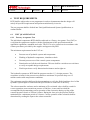
Oppgave tekst
1)
2)
3)
Design a ROV Skid called RITS – equipped with a torque tool, hot stab, manipulator
and a tool tray.
Create the documentation FMC Technologies normally require for a project.
- Except documents that explain additional equipment, like test units and
transport units.
Present at least one example of how the robotics can improve subsea operation with its
increased accuracy.
The rest of the pre-study report is implemented in the SPC (Appendix D) - the progress
reports are added as appendix E.
I
Declaration
I, Magnus Nørstebø, hereby declare that this dissertation is all my own work and the sources
of information and material I have used have been fully identified and properly acknowledged
as required.
II
Acknowledgment
I would like to thank all of those who have helped me through the process of writing this
dissertation.
First of all, I would like to thank my supervisor Olav Egeland and Dan Lindkjølen for their
guidance and helpful tips, while supporting me through the process of finalizing this
dissertation.
Thanks to Per Olaf Tangen for help with technical issues, and Lars Thingelstad for help with
Visual Components.
I want to credit the Norwegian University of Science and Technology in Trondheim for
making it possible to combine university studies and an athlete career with Drammen
Håndballklubb at top national level. In a unique way NTNU facilitates for Master of Science
studies during a sports career. A special thanks to Mr. Jan-Erik Tangen who has been my
contact with the university in this respect.
Additionally, I would like to thank my "text-controllers": Monique Lier Nes, Atle Nørstebø
and Sidsel Nørstebø, for their patience, love and support throughout this period. I could not
have done this without them.
.
III
Executive Summary
Most subsea installations have their own, integrated control and automation systems. In cases
where this is impossible or the mechanism fails, the only unit that can handle such problems is
the ROV. This makes the ROV essential for subsea intervention. However, challenging
conditions makes the ROV operations difficult. This report will present a new tool called
RITS - ROV Intervention Tool Skid, created to simplify these subsea operations.
The RITS system is developed by utilizing conventional subsea technology only. The main
idea is to introduce a fixed docking solution. It will ensure a rigid and fixed position between
the ROV and the ROV panels. The docking receptacle, an API 17D, will secure a completely
locked connection to the subsea unit. From this rigid position the operator may perform the
work without any disturbance of the water flow.
The locked position provides new opportunities for the ROV; it opens for pre-programmed
control of the manipulator and other tools. Robotics technology is frequently used in the
onshore industry; however lack of fixed positions has previously excluded robotics subsea.
This is changed by the new docked position, and an example of a pre-programmed
manipulator will be presented as a part of this thesis.
A manipulator requires a hydraulic system, which can be designed to operate more than one
manipulator. The hydraulic systems are controlled by an embedded control unit connected to
a computer with a control screen (HMI). The extra capacity of the hydraulic system is used to
operate special tools, which are installed inside cassettes. RITS will be able to carry three
cassettes at the time, and the customer can choose between five cassettes depending of what
kind of operation the ROV is supposed to perform. The different cassettes all contain different
tools, and since an HPU is installed, even a hot stab cassette is possible.
This study indicates that the cassettes, the manipulator and the HPU system developed will
work. The docking system however needs extensive testing before RITS can be produced. If
the docking gives satisfying results during the tests, all the required documentation and design
specifications are presented. The docking solution is the component making all the other
systems possible.
The RITS should therefore be able to improve the working situation for the ROV operations.
IV
Sammendrag
De fleste undervannsinstallasjoner har egne systemer for installasjon. I situasjoner hvor dette
er umulig eller mekanismen feiler er det eneste hjelpemiddelet en ROV. Dette gjør ROVen
avgjørende for undervannsoperasjoner. Utfordrene arbeidsforhold på havbunnen gjør
undervannsoperasjoner vanskelige. Denne rapporten vil presentere et nytt verktøy som vil
forbedre arbeidsposisjonen til ROVen, verktøyet er kalt RITS, Rov Intervention Tool Skid.
RITS er laget ved hjelp av normale undervannsløsninger, hvor hovedideen er basert på en ny
tilkoblings metode. Denne faste tilkoblingen vil sikre en solid kobling mellom ROVen og
ROV panelet på komponenten under vann. Koblingen som brukes er en API 17D kobling, og
planen er at denne vil sikre roligere arbeidsforhold nede på havbunnen.
Den nye oppdaterte koblingen åpner et marked av nye potensielle løsninger, hvor blant annet
forhåndsprogrammerte manipulatorer vil forbedre undervannsarbeidet. Roboteknikk gjør dette
mulig, og er et verktøy som er mye brukt i landindustrien. Mangelen på faste punkter har ført
til at roboteknikk har vært lite brukt under vann. Med den nye oppkoblingsmetoden kan
derimot roboteknikk tas i bruk også i undervannsbransjen, og et eksempel på hvordan dette
kan gjøres er vist i oppgaven.
En manipulator krever et hydraulisk system. Slike systemer kan enkelt oppjusteres til å
håndtere flere komponenter. De hydrauliske systemene krever kontrollenheter koblet til en
skjerm om bord i fartøyet på havoverflaten. Siden disse systemene allerede er laget kan andre
undervannsverktøy også installeres i RITS. Verktøyene plasseres i standardiserte kassetter.
RITS vil kunne håndtere tre kassetter av gangen, mens det finnes fem forskjellige alternativer
når det kommer til kasser. Kunden velger de kassettene som passer best for den planlagte
operasjonen. RITS inneholder et HPU system som muliggjør bruk av en Hot Stab, som er et
viktig verktøy under vann.
Studien viser at teknologien som får kassetter, manipulator og HPU system til å virke er
tilfredsstillende. Det er ingen grunn til å tro at RITS ikke skulle fungere. Likevel er
tilkoblingsmetoden og RITS sine bevegelse i vann uprøvd. Skulle testene av disse to tingene
være tilfredsstillende er all annen dokumentasjon klargjort, og RITS klar for operasjon.
Likevel henger alt på om hovedideen med ny tilkoblingsmetode fungerer godt i virkeligheten.
V
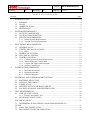
Contents
Abbreviations ............................................................................................................................. 1
Chapter One - Introduction ........................................................................................................ 2
1.1
The RITS idea .............................................................................................................. 3
1.1.2
1.2
Need for RITS ...................................................................................................... 4
Market for RITS .......................................................................................................... 5
1.2.1
Areas in the world have different sea depths ....................................................... 5
1.2.2
Forecasted Wells - tie-in and tree on wire............................................................ 7
1.3
Working class ROVs ................................................................................................... 8
Chapter Two - RITS Interface .................................................................................................... 9
2.1
API 17D - interface...................................................................................................... 9
2.2
API 17D interface - Bucket ....................................................................................... 10
2.3
The locking dog system ............................................................................................. 11
Chapter Three - Tools .............................................................................................................. 12
3.1
Cylinders .................................................................................................................... 12
3.1.1
Double acting cylinder ....................................................................................... 14
3.1.2
Fastening method ............................................................................................... 14
3.1.3
Cylinder position ................................................................................................ 15
3.2
Guiding System ......................................................................................................... 16
3.3
Brackets locking mechanism ..................................................................................... 16
3.4
Force capacity of the cylinder ................................................................................... 18
3.5
Cylinder Lengths .................................................................................................... 18
3.5.1
The RITS cylinders ............................................................................................ 19
3.6
Torque Tool ............................................................................................................... 20
3.7
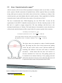
Hot Stab ..................................................................................................................... 21
3.7.1
Two hot stab Cassettes solutions ........................................................................ 22
VI
Chapter four - The Structure design ......................................................................................... 23
4.1
RITS material choice ................................................................................................. 23
4.2
Corrosion ................................................................................................................... 26
4.3
Profile of structure ..................................................................................................... 27
4.4
Assembling the structure ........................................................................................... 29
4.4.1
Bolted structures ................................................................................................. 29
4.4.2
Welded structures ............................................................................................... 31
4.5
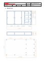
Outer Dimensions of RITS ........................................................................................ 32
4.6
Strength of structure .................................................................................................. 33
4.7
Strength analysis ........................................................................................................ 36
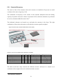
Chapter Five - The Cassettes .................................................................................................... 37
5.1
Modes of operations .................................................................................................. 37
5.2
The Cassette Design .................................................................................................. 38
5.2.1
Cassette Buoyancy ............................................................................................. 39
5.3
The Cassettes Type One with an API interface ......................................................... 40
5.4
The Cassette type two for Tool Carriers .................................................................... 45
5.5
Hose - Cassette hydraulic supply............................................................................... 48
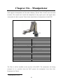
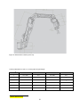
Chapter Six - Manipulator ........................................................................................................ 49
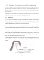
6.1
Kinematics, Visual Components and Python Programming ..................................... 51
6.1.1
Kinematics .......................................................................................................... 51
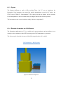
6.1.2
Visual Components ............................................................................................ 52
6.1.3
Python................................................................................................................. 53
6.1.4
Example of robotics on a RLWI-stack ............................................................... 53
Chapter Seven - Hydraulic System .......................................................................................... 54
7.1
Hydraulic Schematics ................................................................................................ 55
7.1.1
Valves used in the RITS Schematics.................................................................. 56
VII
7.2
ROV hydraulic system (Tellus system) ..................................................................... 59
7.2.1
Filter ................................................................................................................... 59
7.2.2
The compensator ................................................................................................ 61
7.2.3
Valve Pack#2 valve pack for the dirty system ................................................... 62
7.2.4
The hydraulic motor ........................................................................................... 63
7.3
The Clean system - HPU system ............................................................................... 65
7.3.1
The Pump ........................................................................................................... 65
7.3.2
The clean side compensator ............................................................................... 67
7.3.3
Valve Pack.......................................................................................................... 69
Chapter Eight - Control Unit .................................................................................................... 70
7.1
Valve pack - Control Systems ................................................................................... 70
7.1.1
PWM16 - Control Card ...................................................................................... 71
7.1.2
Titan 4 - Control system ..................................................................................... 71
7.1.3
CUTE - Communication Distribution Board ..................................................... 72
7.2
Electricity Can ........................................................................................................... 72
7.3
RCU - Remote Control Unit for the torque tool. ....................................................... 73
7.4
Control system Hierarchy .......................................................................................... 73
7.5
Signal ......................................................................................................................... 74
Chapter Nine - Graphic User Interface..................................................................................... 75
9.1
Sensors ....................................................................................................................... 76
9.1.1
Sensor Signals to surface.................................................................................... 76
Chapter Ten – Buoyancy .......................................................................................................... 78
10.1
Buoyancy in the structure profiles ............................................................................. 79
10.1.1
The Buoyancy Elements ..................................................................................... 80
10.1.2
Adjusted elements .............................................................................................. 81
10.1.3
Precaution of buoyancy element positioning ..................................................... 82
VIII
10.2
Centre of Gravity (CoG) ............................................................................................ 83
Chapter Eleven - Interface to the ROV .................................................................................... 84
Chapter Thirteen - Discussion .................................................................................................. 87
Chapter Fourteen - Conclusion ................................................................................................ 90
Bibliography ............................................................................................................................. 91
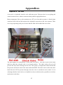
Appendices ............................................................................................................................... 95
Appendix A - Hot Stab ......................................................................................................... 95
Appendix B - Hot Spots........................................................................................................ 98
Appendix C - Visual Components Programming (Python-script)........................................ 99
Appendix E - Project Progress............................................................................................ 129
Figures
Sources market with MN Created by: M.Nørstebø, spring 2014
Figure 1: New systems provided by the docking interface on RITS [MN] ............................... 2
Figure 2: Components in RITS [MN] ........................................................................................ 3
Figure 3: Illustration of decreasing number of human interactions [MN] ................................. 4
Figure 4: Graph that illustrates numbers of wells in the world - by depth [source 1]. ............... 5
Figure 5: Wells over the world in 2012 [Source 1] .................................................................... 6
Figure 6: Model of an API 17D size 1-4 [MN] .......................................................................... 9
Figure 7: API 17D - drawing modified from FMC archive [MN] ............................................. 9
Figure 8: Extended interface bucket capability [MN] .............................................................. 10
Figure 9: An extended API bucket [MN] ................................................................................. 10
Figure 10: Locking dog assembly [Source 4] .......................................................................... 11
Figure 11: The spring loaded locking dog pin [MN] ............................................................... 11
Figure 12: Simplified how the Cylinder works [source 6] ....................................................... 14
IX
Figure 13: Cylinder with two fastening rings [source 6]. ........................................................ 14
Figure 14: Solution for mounting of cylinder beneath the structure [MN] .............................. 15
Figure 15: Guiding system of POM [MN] ............................................................................... 16
Figure 16: Locking cylinder for the cassettes [MN] ................................................................ 16
Figure 17: Locking mechanism for the cassettes [MN] ........................................................... 17
Figure 18: The cylinder used in RITS [MN] ............................................................................ 19
Figure 19: Torque Tool with ROV handle ............................................................................... 20
Figure 20: A 6 Line Hot Stab - both inside and outside [Source 10] ....................................... 21
Figure 21: An extended hot stab, customized to fit inside an API 17D [MN and Source 10] . 21
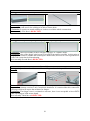
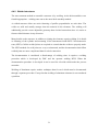
Figure 22: Examples of syntactic foam [source 14] ................................................................. 25
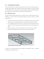
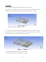
Figure 23: Example of a skid structure [MN] .......................................................................... 29
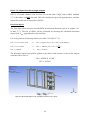
Figure 24: The Structure of RITS [MN] .................................................................................. 32
Figure 25: Horizontal Impact Load - and impact position (Case 1) [MN] .............................. 34
Figure 26: Force applied from beneath (Case 2) [MN] ............................................................ 35
Figure 27: Vertical Impact Load on most exposed corner [MN] ............................................. 35
Figure 28: Vertical Impact Load on exposed element, Case 3 [MN]....................................... 35
Figure 29: Cassette Configuration [MN]. ................................................................................ 37
Figure 30: The buoyancy elements dedicated the cassettes [MN] ........................................... 39
Figure 31: Adjustments created to fit the cylinder [MN]. ........................................................ 40
Figure 32: Cylinder mounting ears, cassette type one [MN] ................................................... 41
Figure 33: Mounting of cassette type two, note cylinder direction [MN]................................ 41
Figure 34: Illustration of the Torque Cassette [MN]................................................................ 42
Figure 35: Maximum buoyance possible inside the torque tool [MN] .................................... 42
Figure 36: The Cylinder Stab Cassette, with all the extra components making it work [MN] 43
Figure 37: The holder cassette [MN] ....................................................................................... 44
Figure 38: Direction of cylinder due to cassette type [MN]..................................................... 45
X
Figure 39: Weight of the components and the total weight of the tool cassette [MN] ............ 46
Figure 40: Free stab cassette [MN] .......................................................................................... 46
Figure 41: Hose retrieval system [MN].................................................................................... 47
Figure 42: Example of guiding system of flex hoses 200mm [MN] ........................................ 48
Figure 43: Guiding of the hoses will be arranged between two gratings [MN] ....................... 48
Figure 44: Measurement of Titan 4 [Source 24] ...................................................................... 50
Figure 45: Kinematics explanation of the robotics [MN] ........................................................ 51
Figure 46: Screen shot of Visual Components ......................................................................... 52
Figure 47: Simulated example in VC ....................................................................................... 53
Figure 48: Schematics created in Visio [MN]. ......................................................................... 55
Figure 49: 4-3 Solenoid valves spring loaded [MN] ................................................................ 56
Figure 50: Picture of solenoid valve: Solenoid operated spool valve. ..................................... 57
Figure 51: Drawing from previous FMC project [FMC] ......................................................... 57
Figure 52: Wandfluh BM4D32-G24-M55-M35 (Schematic) on the left [MN]....................... 58
Figure 53: A pressure relief valve [Source 28] ........................................................................ 58
Figure 54: Picture of pall 9050 taken from the datasheet provided from Pall [source 29] ...... 60
Figure 55: Explanation of compensator volume estimation Excel [appendix C] [MN] .......... 61
Figure 56: Data and picture of the compensator [Source 28]................................................... 62
Figure 57: The valve pack two with 5 solenoids [FMC]......................................................... 62
Figure 58: Picture of a F11 Motor/Pump [Source 31].............................................................. 63
Figure 59 : Basic formulas for hydraulic motors ..................................................................... 64
Figure 60: Volumetric efficiency [Source. 31] ........................................................................ 64
Figure 61: Pump formulas from the Parker catalog (Source 31] ............................................. 65
Figure 62: Shaft connection between the motor and the pump [MN and Source 31]. ............. 66
Figure 63: Huco, multibeam - aluminum [Source 30] ............................................................. 66
Figure 64: Compensators placed in a rack [MN and source 30] .............................................. 68
XI
Figure 65: Schematic of a standard hot stab [Source 36] ......................................................... 69
Figure 66: Copy of Schematics [MN] ...................................................................................... 69
Figure 67: Picture of a valve pack from Innova [Source 37] ................................................... 70
Figure 68: PWM 16 [Source 38] .............................................................................................. 71
Figure 69: Control card for Titan 4 [Source 39] ...................................................................... 71
Figure 70: CDB from Innova [Source 40] ............................................................................... 72
Figure 71: Model of the RCU from the OMM [Source 41] ..................................................... 73
Figure 72: Hierarchy of control units [MN] ............................................................................. 73
Figure 73: Concept drawing of the HMI [MN] ........................................................................ 75
Figure 74: Speed Sensor [Source 31] ....................................................................................... 77
Figure 75: Pressure sensor [Source 42] .................................................................................... 77
Figure 76: The buoyancy package ........................................................................................... 80
Figure 77: Example of the last buoyancy element may look [MN] ......................................... 80
Figure 78: Adjusted Elements .................................................................................................. 81
Figure 79: How the thruster will work true RITS [Source 40 and MN] .................................. 82
Figure 80: How to adjust CoG [MN] ....................................................................................... 83
Figure 81: Examples of bolts (CAD12) [FMC] ....................................................................... 84
Figure 82: Fastening Rods........................................................................................................ 84
Tables
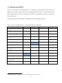
Table 1: Percentage well less than 2000 meters. ........................................................................ 6
Table 2: Depths of subsea wells - and the deepest existing well in area (2013)2 ....................... 6
Table 3: Planned forecasted wells, and depths that are increasing most in percentage. ............ 7
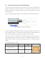
Table 4: Cylinder lengths ......................................................................................................... 18
Table 5: Measurements of Sylinderteknikk cylinders [source 7] ............................................. 19
XII
Table 6: System requirements needed to meet FMC (customers) needs ................................. 20
Table 7: Info of a hot stab ........................................................................................................ 22
Table 8: Al 6082-T6 material features ..................................................................................... 24
Table 9: Important capabilities for Syntactic Foam ................................................................. 25
Table 10: Square Profile measurements in millimeters [MN] ................................................. 28
Table 11 presents some different bolt assemblies, none of them suited for RITS ................... 30
Table 12: All tables is stress and deformation analysis of structure ........................................ 36
Table 13: An overview of which cassettes and the use of elements ........................................ 39
Table 14: Standard Cassette type 1 - weights .......................................................................... 40
Table 15: Weight of all the components and the total weight of the torque cassette ............... 42
Table 16: Weight of all the components and the total weight in the cylinder stab cassette ..... 43
Table 17 Weight of the components and the total weight of the cassette ................................ 44
Table 18: Weight of all the components and the total weight if the cassette ........................... 46
Table 19: Weight of all the components and the total weight if the cassette ........................... 47
Table 20 Data for Titan 4 ......................................................................................................... 49
Table 21: Kinematics for Titan 4 - 6 revolute joints and joint lengths .................................... 50
Table 22 Abilities for Parker F11 motor sizes [Source 29]...................................................... 64
Table 23: Summary over consumption of fluids required to operate/override a system ......... 67
Table 24: Electric Can [Source: FMC - Per-Olaf Tangen] ...................................................... 72
Table 25: Signal configuration ................................................................................................. 74
Table 26: Weight of the components in RITS .......................................................................... 78
Table 27: Calculation of buoyancy in the structure ................................................................. 79
Table 28: Rejected Interface Connection ................................................................................. 85
Table 29: Approved Interface Connection ............................................................................... 86
XIII
Abbreviations
API
CDB
CoG
FMC
GUI
HMI
NTNU
NDT
RCU
RITS
RLWI
ROV
VC
WROV
XT
American Petroleum Institute
Communication Distribution Board
Center of Gravity
Food Machinery Corporation
Graphic User Interface
Human Machine Interface
Norwegian University of Science and Technology
Non Destructive Testing
Remote Control Unit
ROV Intervention Tool Skid
Riserless Light Well Intervention
Remotely Operated Vehicle
Visual Components
Working Class ROV
Christmas Three
1
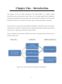
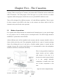
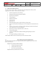
Chapter One - Introduction
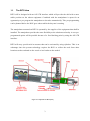
The purpose of the new ROV Intervention Tool Skid (RITS) is to improve subsea
intervention. Subsea intervention in this context is the tooling making subsea installation,
operation and maintenance possible under water. By definition all "hands-on" activities made
by the ROV and its tools is subsea intervention. It does not include inside bore operation.
The main idea is to replace the present grabber manipulator on the ROV with a new and more
solid interface connection. It will provide a more rigid position which will make the operation
subsea easier. A rigid system will open for other features.
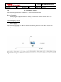
Figure 1 illustrates the main idea of RITS create some new situations that will open for new
system for subsea use.
Figure 1: New systems provided by the docking interface on RITS [MN]
2
1.1
The RITS idea
RITS will be designed with an API 17D interface which will provide the skid with a more
stable position on the subsea equipment. Combined with the manipulator it opens for an
opportunity to pre-program the manipulator to do tasks automatically. This pre-programming
can be planned before the ROV goes subsea while the day-rate is running.
The manipulator mounted on RITS is operated by the supplier of the equipment that shall be
installed. The manipulator provides the same flexibility as the solution used today. A new preprogrammed option will be possible because of a fixed docking point by using the API 17D
interface.
RITS will carry special tools in cassettes that can be activated by using cylinders. This is an
advantage since the present technology requires the ROV to collect the tools from other
locations such as onboard on the vessel or in a basket on the seabed.
Figure 2: Components in RITS [MN]
3
1.1.2 Need for RITS
Bad visibility, flowing water and old systems makes the ROV operation difficult, inefficient
and time-consuming - and it leads to high costs for the installation company. The new
docking system will provide a solution that can solve this issue. A solid parking allows the
ROV to be more accurate and apply more force on the installation, in addition to improve the
working situation for the operator.
The present ROV operations require two skilled ROV operators. One operator keeps the ROV
in place with the grabber manipulator, while the other operates the equipment. This
arrangement makes the operators dependent on each other, in addition to communicate with
the equipment experts (the suppliers). The equipment engineers know how the installation
should be handled. An efficient operation is therefore depended on good communication
between at least three people, which not necessarily are sitting in the same room. Figure 3
illustrates the present solution that requires three people, while the right side only need two
people.
Figure 3: Illustration of decreasing number of human interactions [MN]
RITS will decrease the number of human interactions since the parking of the ROV requires
one ROV operator only. The manipulator mounted on RITS is operated by the supplier which
also results less work for the ROV operator. An additional benefit is a closer cooperation
between to areas of the industry that during the years has driven apart.
4
1.2 Market for RITS
An evaluation of the existing subsea wells is made in order to analyze the potential market for
RITS. This is required to provide the project with a reasonable technological aim since there
are considerable costs related to creating a system that can handle all depths and challenges.
The development cost can be significantly reduced if the design criteria are limited to handle
80 % of the market. A successful system can be developed further to handle the entire market.
This chapter will explain which external mechanisms that will limit the first edition of the
RITS.
1.2.1 Areas in the world have different sea depths 1
The cost of a skid that can withstand the pressure on the deepest wells of more than 3000
meter can be excessive. The marginal cost of larger depths designs increases exponentially
due to the increase of external pressure. To have manageable cost RITS will be designed to
operating conditions for wells depths down to 2000 meters.
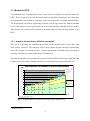
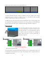
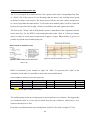
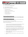
The table and graph below provides an overview of all the subsea wells in the world. The data
is taken from Quest Subsea Database and shows existing and forecasted wells until 2017.
Wells
Development in number of active subsea wells
10 000
9 000
8567
556
8 000
428
7 000
318
241
5053
5 000
3362
60
101
778
67
124
933
70
141
1131
167
1283
92
1381
505
2363
2523
2000+ m
2162
1974
190
176
2 000
1 000
251
107
78
3 000
144
616
406
325
6 000
4 000
CAGR for period
2013 - 2017 is
11.1% pa.
1500-2000 m
1695
600-1500 m
1494
0-600 m
2423
2587
2769
2929
3058
3262
2007
2008
2009
2010
2011
2012
3642
3964
4304
4622
4866
2016
2017
0
2013
2014
2015
Source: Quest Subsea Database Feb 2013
Last revision: BJ - 13 Dec 2013
Figure 4: Graph that illustrates numbers of wells in the world - by depth [source 1].
1
(B.Jahnsen, 2013)
5
Year
Figure 4 illustrates the depths of the existing and forecasted subsea wells in the world. Even if
the deep wells seem to increase, the main market is wells less than 2000 meters. Experiences
by FMC-engineers show that the expenses of going deeper than 2000 meters usually cost
more than it is worth. The table below confirms that a design depth on 2000 meters covers
more than 90 % of the market
Table 1: Percentage well less than 2000 meters.
Year
2013
2017
All Wells
5732 wells
8561 wells
Wells less than 2000
meters
5588 wells
8011 Wells
Percentage less than 2000
meters
97.5 %
93.5 %
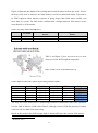
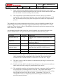
Table 2 and figure 5 gives an overview over areas
where use of the RITS might be impossible.
Figure 5: Wells over the world in 2012 [Source 1]
Table 2: Depths of subsea wells - and the deepest existing well in area (2013)2
Area
Norway
British
West Africa
Brazil
Gulf of Mexico
Asia/Pacific
0-69 m
74 wells
16 wells
48 wells
32 wells
70-600 m
815 wells
923 wells
240 wells
298 wells
229 wells
297 wells
601-1500 m
20 wells
617 wells
445 wells
293 wells
68 wells
1500+ m
31 wells
135 wells
131 wells
-
Deepest
1100 m
507 m
1654 m
2580 m
3048 m
1343 m 2
The only area in the world where a skid's design limited to 2000 meters may cause a problem
is in the Gulf of Mexico (GoM) and in Brazil. Although, in these fields the majority of subsea
wells are still less than 1500 meters deep.
Based on this analysis the skid's design depth is found sufficient when rated at 2000 meters.
2
(B.Jahnsen, 2013)
6
1.2.2 Forecasted Wells - tie-in and tree on wire
RITS is designed as a product to help subsea components that are not signal/power-wired with
the surface. In addition to intervention work (maintenance on existing wells) RITS can be
useful for new installation of XTs. Both tree on wire and tie-in operations are subsea tasks
that can benefit from using RITS.
Tree on wire is an installation of a XT without the marine riser, which is a continuous pipe
from the platform down to the seabed. Since the riser is not installed, it is challenging to
communicate with the XT down on seabed. To be able to operate the XT, a ROV is frequently
used. Installations like this require the ROV to handle the landing of the XT in addition to
connecting the communication line afterwards (Umbilical).
Tie-in operations are in a similar non-commuting state as the tree on wire. Tie-in means the
operation to plug/connect the production line to the XT. It has been developed systems to
make this operation easier; however all of them are heavily dependent of the ROV.
Table 3 is a result of the information provided in Figure 4 - overview of depths of wells;
however separated into percentage increase of forecasted wells due to depth.
Table 3: Planned forecasted wells, and depths that are increasing most in percentage.
Area
2013 - existing wells
2014
2015
2016
2017
0-600 m
3642 wells
8.8 %
8.6 %
7.4 %
5.3 %
601-1500 m
1695 wells
16.5 %
9.5 %
9.3 %
6.8 %
1501-2000 m
251 wells
29.5 %
24.9 %
24.4 %
22 %
2000+ m
144 wells
67.4 %
32 %
34.6 %
29.9 %
The table points out a tendency that the wells in the future will get deeper. Tree on wire is a method
that first of all is used on deep wells, while tie in is a work performed on all depths. The calculation
in table 3 exemplifies a high percentage increase in deep wells: yet the number of wells will still be
lower than the wells less than 2000 meters. Knowing from table 2 that the deepest wells are over
3000 meters deep, it is assumed that the cost of calculating RITS with a 3000 meter design will be
expensive.
This information gives an indication that RITS may be more suited to handle tie-in and intervention
than tree on wire; however it the depths are less than 2000 meters RITS still an option.
7
1.3 Working class ROVs
The size of the ROVs will determine the size of RITS as the large ROVs will not have any
difficulties carrying a small skid; while the smallest ROVs will have a max allowable size of
RITS. Skid-structure which are larger than the ROV are problematic as they are exposed to
hits from the sides.
The table below presents the ROVs commonly used in the offshore industry.
Table 4: Overview of common ROVs sizes - with operational depths over 2000 meters
WROV - type and supplier 3
HD-ROV
Schilling
UDH-ROV
Schilling
Centurion QX,200
Subsea 7
Centurion QX, 300
Subsea 7
ACV
Subsea 7
Hercules
Subsea 7
Quantum
Subsea 7
Diablo
Subsea 7
Demon
Subsea 7
Magnum Plus
Oceaneering
Maxximum
Oceaneering
Millenium Plus
Oceaneering
Triton XTR
Slingsby
3
Width
1.7 meter
Length
2.5 meter
Height
1.9 meter
Weight
3700 kg
1.9 meter
3 meter
2 meter
5270 kg
1.7 meter
2.5 meter
1.7 meter
2500 kg
1.7 meter
2.5 meter
1.7 meter
2900 kg
1.9 meter
3.4 meter
2 meter
-
1.85 meter
2.4 meter
2.05 meter
2750 kg
2 meter
3.58 meter
2 meter
5350 kg
2.04 meter
2.65 meter
1.82 meter
3050 kg
1.83 meter
2.95 meter
2 meter
3500 kg
1.55 meter
2.59 meter
1.85 meter
3060 kg
1.83 meter
3.048 meter
1.85 meter
4850 kg
1.68 meter
3.3 meter
1.92 meter
3990 kg
1.7 meter
2.5 meter
1.7 meter
3600 kg
(Oceaneering, 2013) , (Subsea 7, 2013), (Technologies, 2013), (i-Tech, 2013),
8
Chapter Two - RITS Interface
The RITS interface unit is the component that shall ensure a rigid and stable position. The
present ROV systems require a 5 function grabber manipulator that is operated manually by
personnel topside. The grabber manipulator will grab the ROV handles mounted on the
subsea installation. This operation is challenging because of movement in the sea and poor 2D
visibility. The idea is to replace the manipulator with a connector that allows RITS to dock
onto the subsea equipment and keep the ROV in a defined stable position resulting in faster
and more accurate operation.
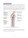
2.1
API 17D - interface
The American Petroleum Institute has developed various standards for
use by the petroleum industry. The API 17D is the standard describing
the most common connector interface. FMC guidelines demand that an
API 17D to be applied in an attempt to standardize the interface.
Subsea systems are installed with override functions. Common for
Figure 6: Model of an API 17D
size 1-4 [MN]
those overrides is that they require a special tool as e.g a hot stab or
torque tool. To ensure a proper access for the tools, a solution where all
the special tool interfaces are installed inside an API 17D interface is selected.
The API 17D has three standardized sizes. The most suitable size for RITS is the API 17D 1-4
the dimensions of the interface are given in figure 6.
The interfaces are built in workshops, which causes a free material selection. It is preferred to
use the same material as the rest of RITS to avoid galvanic corrosion. The front may be
installed with a rubber element to decrease the impact forces of the landing.
Figure 7: API 17D - drawing modified from FMC archive [MN]
9
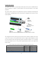
2.2
API 17D interface - Bucket
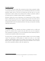
The API 17D interface require modifications on the ROV panel. The ROV panel is the unit
where all ROV handling and override mechanisms are placed. Many ROV panels are installed
with API 17D interfaces; however they are installed in a way that may cause problems for
RITS. If RITS should dock on an existing interface bucket, the ROV and the manipulator will
be disabled because of no working space. To avoid this problem a new API 17D interface
bucket needs to be installed.
Figure 8: Extended interface bucket capability [MN]
The extended bucket is important to make RITS functional, and it is a critical unit to secure
the new connection method. The ROVs are installed with thrusters that can make the ROV
neutral weighted. The principle with extended interface buckets will need testing before RITS
can be tried in operation; yet the grabber manipulator method make it work with a less rigid
system. It is an indication of that the API 17D method should work.
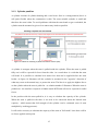
Figure 9: An extended API bucket [MN]
The API 17D interface buckets are commonly used on several subsea projects. They are, as
the receptacle, created in many different materials, while the size is standardized. Figure 9
illustrates an API 17D interface bucket, and an example of how the buckets may be extended
to satisfy the demands of RITS.
The strength requirements will depend of the ROV model - and will require a separate
dimensioning for each specific project.
10
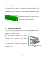
2.3
The locking dog system 4
The API 17D interface will ensure that RITS has a steady position during the operation; still
there is a chance that RITS will "fall out" of the interface. To avoid this problem a locking
system are implemented between the bucket and the receptacle.
Figure 6 reveals two holes that seem without purpose. Those two holes are actually important
for the locking system, and are called locking dogs. A locking dog is a pin in the receptacle
that will be pushed into a fitting hole in the interface bucket. RITS will be totally fastened as
long as the pin is pushed inside the bucket.
This system is standard on the API 17D interface; however the locking dog pin is not always
installed. The system on figure 10 is actually an Oceaneering invention, but by implementing
a dedicated hydraulic line to the locking dogs in RITS will make this system possible for all
the interfaces.
As figure 10 is illustrating, the locking dog
has a spring installed. The purpose of this
spring is to retrieve the locking pin if the
system loses its power. It is a safety
mechanism that makes it possible for the
ROV to pull away in an emergency situation.
If the locking dogs are not installed, the
Figure 10: Locking dog assembly [Source 4]
hydraulic lines will be plugged with a blindflange.
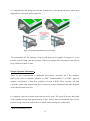
In addition to a solid extended bucket it is possible to
install a system that mechanically informs when the
locking dogs are installed. The locking dogs will
push a pin out, and the camera on the ROV will be
able to verify the status of the connection.
4
Figure 11: The spring loaded locking dog pin [MN]
(Oceaneering, 2009)
11
Chapter Three - Tools
RITS will be designed with tool packages, called cassettes. The cassettes will contain the API
interface and the special tools. The tools in the cassettes will be protected inside RITS during
transportation subsea and a cylinder will activate the cassette by push it in operational
position.
This chapter will explain the cylinders that activate the tool-cassettes, and a brief explanation
of the special tools inside the cassettes.
3.1
Cylinders
RITS need three cylinders to be able to activate all three cassettes. It is important that the
cylinder can withstand the design depth determined to be 2000 meters depth.
Hydraulic cylinders exist in all sizes. A combination of available space and need of strength
will determine which type of cylinder that is applicable for RITS. The diameter of the piston
and the hydraulic pressure acting on the piston determines the strength of the cylinder. It
means that the needed force can be important when determining the cylinder size; however it
is preferable to use a small cylinder to reduce the weight of the skid.
The required strength for the cassette cylinders in RITS is limited. Their only purpose is to
push the cassettes, in addition to withstand the forces applied when RITS connects the
interface bucket.
The idea is to design the skid with a lock mechanism that will reduce the forces on the
cylinder when connected. It decreases the demands for strengths, which reduce the size of the
cylinder.
The cylinder shall handle the friction between cassette and structure, while the locking
mechanism should handle the parking forces.
As a result, small cylinders will be strong enough for RITS, and results in the desired low
constructional weight.
12
Pneumatic cylinder 5
In an attempt to reduce the weight of the construction an idea of using a pneumatic cylinder
was presented. Since there is no pneumatic system in the RITS system the idea was to fill the
pneumatic cylinder with oil. The idea was rejected pretty fast since there are very strict
requirements for subsea cylinders, and reconstruct and re-certificate a pneumatic cylinder to
be operated with oil as a hydraulic cylinder would be very demanding.
Pneumatic cylinders have stricter requirements as the compressed gas will have explosive
behavior. Additionally they operate with a working pressure less than 30 bar which result in
need to fine-tune pressures by a few bars. Cylinders in RITS should be reliable and robust,
and Sylinderteknikk warned for mechanical problems if the design was dependent controlling
with of fine-tuned pressures.
Hydraulic cylinder
The hydraulic cylinders are commonly used subsea as hydraulic units are reliable and
powerful. The cylinder needs to operate on the same fluid as the rest of the components.
These components are operating on oil. To avoid complications with the fluids and pressure it
is natural to pick a hydraulic cylinder for the cassettes.
The main reason to seek other solutions than hydraulic cylinders was the concern regarding
weight. The requirements of RITS-cylinders are limited, and results in a low weight
component. Sylinderteknikk weighted a Ø30 cylinder (250 mm long) to 2.5kg, which means
that the cylinder is a light component compared to other units inside RITS. It is not worth the
risk to choose a pneumatic cylinder to reduce the weight by 1 kg.
5
Information and recommendation from meeting with Sylinderteknikk - Terje Grimsrud, date: 28/02-14
13
3.1.1 Double acting cylinder 6
A double acting cylinder has two hydraulic lines connected to
the cylinder house, one each side of the piston. The cylinder is
operated by filling fluid on one side of the piston. When one side
is filling up, the other side will drain and the piston and stem
will move. Double acting means that both sides of the piston can
Figure 12: Simplified how the
Cylinder works [source 6]
be filled. Single acting cylinders are often installed with a spring
to force the stem back into start position when the pressure is
bled off.
3.1.2 Fastening method
The cylinder on figure 12 is a double acting cylinder, with
a flange connection. Figure 13 is showing a double acting
with two rings. These two types are identical when it
comes to size and strength, but the fastening methods are
different. The position and space inside RITS will
Figure 13: Cylinder with two fastening
rings [source 6].
determine what fastening method that is the best choice.
RITS is designed with a double acting cylinder with two
rings as fastening method; the reason is presented in
chapter 3.1.3.
Safe-fail-close or safe-fail-open
A safe-fail-close system is often used in situations where cylinders need to go to lock during
failure. It is performed by installing a spring on one side of the piston. This contingency
mechanism will not be required for the cylinders activating the cassettes. It is not critical if
RITS will not be able to pull the cassettes in during transport - it will only require a more
careful transportation.
The contingency spring solution is illustrated on the locking dogs system. It is required for the
locking dogs because RITS will not be able to pull back if the dog pins are activated. The
contingency mode has to be designed for the solenoid valve system in a way that allows the
fluid to drain.
6
(Hydex Sylinderteknikk, 2014)
14
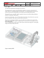
3.1.3 Cylinder position
A cylinder consists of cylinder housing and a steel stem. Steel is a strong material, but it is
still quite flexible when the construction is thin. The most suitable cylinder is small and
therefore the stem is thin. To avoid problems with that the stem bends or get overloaded, the
cylinder must be mounted to give as low unnecessary loads as possible.
Figure 14: Solution for mounting of cylinder beneath the structure [MN]
A cylinder is strongest when the stem is pulled inside the cylinder. When the stem is pulled
fully out it will be exposed for force from the sides. As a result there is a risk that the stem
will bend. It is possible to calculate how much force that can be applied before the stem
breaks. As figure 14 illustrates will the cylinder be mounted in the "opposite" direction of
what may seem as the natural way, to protect the stem. The idea is to apply the highest forces
on the cylinder when the stem is pulled in - as solution number 2 illustrates. When the stem is
pushed out - the interface receptacle is hidden inside RITS and will not be exposed for radial
forces.
In the position with the stem pulled in, it is easy to calculate the capacity of the cylinder.
When the stem is pulled in the there is no need to be concerned about the limited stem
capacity - which means that full strength of the cylinder can be estimated (area of stem
multiplied by working pressure).
It will not be necessary to calculate the capacity of the stem at "full stroke" since there will be
no forces applied at this point.
15
3.2
Guiding System
POM (Polyoxymethylene) is a plastic material, widely used to protect equipment from dirt
and scratches in the subsea industry. The RITS project will use POM to reduce the friction
between the cassettes and the structure. In addition to lower the friction it will secure a proper
guiding of the cassettes. The combination of a proper guiding, and an optimal position of the
cylinder, will secure a reliable handling of the cassettes.
POM is a low cost material. It is softer than the
aluminum, which makes the wear and tear to appear on
the component easiest to replace. The POM will be
fastened to the structure by clips or bolts.
Figure 15: Guiding system of POM [MN]
3.3
Brackets locking mechanism
The most critical situation for the cylinder is the impact forces when the interface receptacle is
pushed into the interface bucket. To avoid that the cylinder will handle all the forces a locking
mechanism for the cassettes is installed.
There are several different methods to lock a cassette.
RITS will use a simple and mechanical solution since the
manipulator can be programmed to do the locking
automatically.
The system consists of a half-cylinder with a handle on top.
The cylinder allows the cassettes to slide freely in one
position, but when the cylinder is turned 90 degrees the
cassette will be locked.
16
Figure 16: Locking cylinder for the cassettes
[MN]
It is important that the design prevents the locking pin to turn during operation, which may
happen due to vibrations during operation.
Figure 17: Locking mechanism for the cassettes [MN]
The manipulator lift the cylinder 5 mm up and then turn the handle 90 degrees (it is not
possible to pull to long since the geometry of the pin is designed in a way that prevents the pin
to be pulled more than 10 mm).
Subsea cylinders adjustment 7
There are strict requirements to equipment used subsea, and there are a few suppliers
approved to deliver hydraulic cylinders to FMC. Sylinderteknikk is an FMC approved
supplier, and because of that their cylinders are used in RITS. Their expertise and long
experience ensures the requirements due to corrosion, pressure limitations and other demands
of the subsea business are met.
It is required a special corrosion protection ring on the stem. The ring will increase the length
of the cylinder housing with approximately 25 mm. Table 5 does not include the extra 25 mm
protective ring extensions, and needs to be added when selecting the cylinder size.
7
(Hydex Sylinderteknikk, 2014)
17
3.4
Force capacity of the cylinder
The force the cylinder needs to overcome is quite small. The strength is calculated by the
piston area multiplied by the fluids pressure. The smallest standard cylinder from
Sylinderteknikk with enough stroke-length is the Ø30 cylinder.
𝑎𝑟𝑒𝑎𝑝𝑖𝑠𝑡𝑜𝑛 × 𝑝𝑟𝑒𝑠𝑠𝑢𝑟𝑒𝑝𝑠𝑖 = 𝑆𝑡𝑟𝑒𝑛𝑔𝑡ℎ 𝑜𝑓 𝐶𝑦𝑙𝑖𝑛𝑑𝑒𝑟𝐴𝑥𝑖𝑎𝑙 𝑑𝑖𝑟𝑒𝑐𝑡𝑖𝑜𝑛
(П × 0.0152 ) × 207 × 105 = 14 625 𝑁
Using POM guiding and the locking mechanism for the cassettes, the cylinder of Ø30 is
strong enough.
The capacity of the cylinder is that strong that there is no point of calculate the friction. The
friction will be reduced because of the guiding system; however the cylinder is strong enough
to relive the cassettes locking mechanism when the impact force appears.
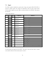
3.5
Cylinder Lengths
RITS will need four cylinders to be able to perform the task it is designed for. Three of the
cylinders will be installed to push the cassettes into operational mode and back to transport
mode. The last cylinder is needed for the cylinder stab cassette. Common for all cylinders is
the limited stroke lengths, which are restricted to push the length of the interface, 181mm
(given in figure 7 - measurements of the interface receptacle).
Table 4: Cylinder lengths
A -length +25mm*
Stroke
OD-outer
IN
Total
Length of stem
length
diameter
Diameter length
203 mm
181 mm
Ø40 - (50)
Ø30
384mm
Tray Cylinder
203mm
181 mm
Ø40 - (50)
Ø30
384mm
Hot Stab Cylinder
* Extra length to customize the cylinder for subsea use (ref. Terje Grimsrud, Sylinderteknikk)
18
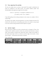
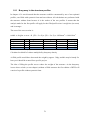
3.5.1 The RITS cylinders
Table 5: Measurements of Sylinderteknikk cylinders [source 7]
Figure 18: The cylinder used in RITS [MN]
19
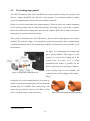
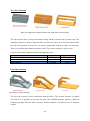
3.6
Torque Tool
A torque tool is the wrench used subsea. Most subsea tasks are performed by the manipulator,
e.g. operation of ROV handles. The torque tool performs more "advanced" task as mechanical
override of failed valves or to mechanically power up a motor or a pump. It is also required to
connect/disconnect Multi-Quick Connectors (MQC), which is a common task since the MQC
has more restricted life cycle than the XTs. The torque tool has an API 17D interface
receptacle which is useful since all the special tools will have a "true API 17D interface"
option, ref chapter 5.3.
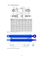
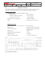
The torque tool exists in several different sizes, RITS will use the most common, the 2700
NM with 200OMM motor.
Table 6: System requirements needed to meet FMC (customers) needs
Mechanical Data 8
Length
600mm
Width
360mm
Diameter
300mm
Weight in Air
39 kg
Weight in Water
30 kg
Torque Range
2700 Nm
Hydraulic Data
Pressure
200 Bar
Flow
36 l/min
Fluid
ISO VG22 (Shell Tellus or equal)
General Data
Axial Force on latches
3000 N
Max Water depth
3000 meters
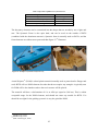
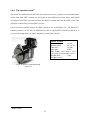
Figure 19: Torque Tool with ROV handle 9
Figure 19 illustrates a torque tool. The ROV handle (the orange grip) will be removed for
RITS use. The torque tool is the only tool that has locking dogs integrated from the supplier.
The locking dog system planned for RITS is a copy of the torque tool system.
8
9
(FMC Technologies, 2010)
(Oceaneering, 2009)
20
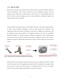
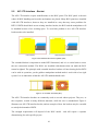
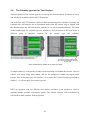
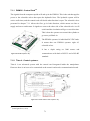
3.7
Hot Stab
It can be challenging to operate all the valves one by one. In cases like that a hot stab becomes
in handy. The purpose of a hot stab is to apply pressurized fluid into a subsea installation,
through a number of ports. The ports send high pressured fluid to open or close integrated
valves in the subsea installation. The advantage with the hot stab is thus that it can operate
several valves at the time.
When the stab gets connected it opens one or several supply lines and return lines to operate
valves. In addition to override scenarios the stab can use its external fluid to operate
motors/pumps. Pressurized fluids are also used to check that connections are properly
tightened; by adding a hot stab to the RITS it becomes more useful also for tie-in projects.
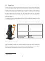
The number of function depends of how many lines the stab has. RITS will use 6 lines 345
bar hot stabs, which can handle three valves (3 supply lines and 3 return lines).
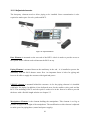
Figure 20: A 6 Line Hot Stab - both inside and outside [Source 10]
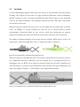
While the torque tool normally has API 17D interface connection the hot stab does not have
any standardized interface connection, but are normally put in operating position by a
manipulator arm. For RITS a new solution is proposed, where the hot stab is installed to an
API 17D interface. It requires some modification of the normal 6L hot stab; though there will
not be any change of function - it will simply be a bit longer than the normal.
Figure 21: An extended hot stab, customized to fit inside an API 17D [MN and Source 10]
21
3.7.1 Two hot stab Cassettes solutions
To increase the flexibility of RITS, it will have a cassette providing a "loose" hot stab. It
means a hot stab that can be operated by the manipulator.
The hot stab system requires more adjustment than the other tools; however to be able to
handle existing XT’s this unit is required, as existing subsea installations not are designed to
handle a hot stab true a API 17D interface.
Table 7: Info of a hot stab
Length
Width
Diameter
Weight in Air
Weight in Water
Pressure
Flow
Fluid, oil
Max Water depth
Hydraulic hoses
Mechanical Data 10
438 mm
various
140 mm
4.5kg
3.5kg
Hydraulic Data
207 Bar (design 380 Bar)
30 lpm
Depending of external system
General Data
2500 meter
Hydraulic interfaces
7/16" x 20 JIC
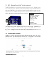
Clean system - Hydraulic Power Unit
A hot stab applies fluid into external systems. Subsea system usually have strict requirements
due cleanness to fluids. RITS is powered by the ROV auxiliary valve pack, which consist of
"dirty" fluid (Tellus). To insert a usable hot stab a special clean system is needed inside RITS.
Systems that provide clean fluids are called a Hydraulic Power Unit (HPU). It is a system that
can make a secondary system flow without mix fluids. The schematic will show what
components that are needed inside the RITS to make a clean fluid system possible.
See Appendix A for a detailed explanation of a hot stab and how it is works.
10
(FMC Technologies, 2010)
22
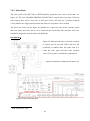
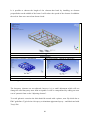
Chapter four - The Structure design
The structure will protect all the sensitive tools inside RITS with its frame. It is important that
the structure is designed so that it will not expose the manipulator or other tools. To work as
intendant it is important to choose the right material, form and profiles of the pieces that
become the structure.
Subsea equipment is exposed to some of the most corrosive environments in the world, even
if the oxygen level is low down on seabed. Equipment stored on the vessels is particularly
exposed to corrosion. It is problematic that equipment, like RITS, is exposed for seawater and
then be stored on deck where the oxygen level is high.
Another material sensitive factor is the weight. Offshore equipment should be easy to handle.
Waves and wind makes lifting operations dangerous; therefore it is important to keep weight
as low as possible.
In addition to the issues mentioned above, costs are an important factor. There are many
materials that fulfill the environmental challenges, however they usually are expensive. The
cheapest material commonly used for equipment in similar environment as RITS is
Aluminum 6082-T6.
This chapter explains the material choices for the structure. Further, different solutions for
how to assemble the structure are discussed.
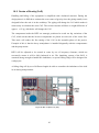
4.1
RITS material choice
Steel is a normal choice of material because of the strength and the experience from many
other subsea projects. There is a design goal to keep RITS as small as possible to make the
ROV moveable. Steel is heavy, which require more buoyancy elements to make RITS neutral
in water. Buoyancy elements are quite big, and exclude the steel solution since it will increase
the size of RITS.
23
Al 6086-T6, is an aluminum quality commonly used for equipment moved up and down in the
sea. The prices are acceptable and the strength is within the wanted range.
Table 8: Al 6082-T6 material features
Properties 11
Density
Hardness, Vickers
Tensile Strength - Yield
Wall thickness less than 5mm
Tensile Strength - Ultimate
Wall thickness less than 5mm
Thermal Conductivity
Metric Values
2.7 g/cc
95
250 MPa
290 MPa
170 W/m-K
Aluminum meets the design requirements to RITS. Aluminum is ranked low in the galvanic
series which makes it vulnerable for galvanic corrosion connected to most other metals. An
advantage with RITS is easy access for maintenance and an objective is to create RITS into a
structure that easily can be changed - if corrosion is considered a problem.
If the aluminum structure should be too weak - steel or "expensive" solutions as titan would
be replacement alternatives.
Buoyancy elements are needed to make RITS buoyant in water. FMC guidelines demands
ROV-tools to not exceed 50 kg under water. Tools that are heavier than 50 kg will cause a
dysfunctional ROV and prevent the RITS from improve the present subsea technique. From a
subsea intervention point of view tools heavier than 50 kg is called ROT (remotely operated
tool), and is another kind of equipment than what RITS are supposed to be. To meet the
requirement from FMC, RITS cannot exceed 50 kg in water.
Chambers filled with air could make the RITS more buoyant. An air-filled system must stand
an outer pressure on 2000 meters sea depth to avoid breaking the air chambers, and require a
thicker, and heavier, layer of material.
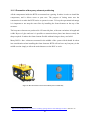
The material called BMTI or Syntactic Foam has proved to stand a sea depth level of 3000
meter. The Syntactic Foam (SF3000) could be blasted into different profiles 12 to improve the
buoyancy (ref table below). Normally Syntactic Foam is delivered in elements that are easy to
customize.
11
12
(Mat Web, 2014)
Phone call with DIAB Norway
24
Table 9: Important capabilities for Syntactic Foam
Properties 13
Weight in air
Seawater Buoyancy
Block size
Depth rating
Metric Values
495 kg/m3
30.2 kg/block
57 liters
3000 meters
The buoyancy elements can be customized into the shapes that are needed by use of glue and
saw. The Syntactic Foam is also quite hard, and can be used on the outside of RITS
(combined with the aluminum structure). Syntactic foam is normally used on ROVs, and the
foam elements are seldom more protected than figure 23 14 illustrates.
Figure 22: Examples of syntactic foam [source 14]
Acetal Polymer 15 (POM) is a hard plastic material normally used as protection for flanges and
seals. RITS will use POM elements for tasks that do not require any strength. A typically area
for POM will be the chambers where the tool cassettes will be placed.
The material will have a deformation of 1% at 4500 psi (equal to 300 bar). This is within
acceptable range for the POM elements, and should not cause any trouble for RITS. If it
should be too tight for the guiding system it is easy the grind the POM.
13
(DIAB-Group, 2014)
(DIAB-Group, 2013)
15
(FMC Technologies, 2006)
14
25
Aluminum weight in water
Archimedes law tells that weight of components in water is calculated to be:
𝑊𝑒𝑖𝑔𝑡ℎ 𝑖𝑛 𝑤𝑎𝑡𝑒𝑟 = 𝑊𝑒𝑖𝑔ℎ𝑡 𝑜𝑏𝑗𝑒𝑐𝑡 − 𝑊𝑒𝑖𝑔ℎ𝑡 𝑜𝑓 𝑑𝑖𝑠𝑝𝑙𝑎𝑐𝑒𝑑 𝑓𝑙𝑢𝑖𝑑
This can be changed to a simpler and more usable equation:
𝑂𝑏𝑗𝑒𝑐𝑡 𝐷𝑒𝑛𝑠𝑖𝑡𝑦−𝑊𝑎𝑡𝑒𝑟 𝐷𝑒𝑛𝑠𝑖𝑡𝑦
𝑂𝑏𝑗𝑒𝑐𝑡 𝑑𝑒𝑛𝑠𝑖𝑡𝑦
× 𝑂𝑏𝑗𝑒𝑐𝑡 𝑊𝑒𝑖𝑔ℎ𝑡 𝑖𝑛 𝑎𝑖𝑟 = 𝑂𝑏𝑗𝑒𝑐𝑡 𝑊𝑒𝑖𝑔ℎ𝑡 𝑖𝑛 𝑤𝑎𝑡𝑒𝑟
The density of salt water is approx. 1030 kg/m3 and the density of aluminum is 2700 kg/m3, it
makes it possible to calculate a percentage to calculate the aluminum weight in water
4.2
Corrosion 16
2700−1030
2700
= 63 % × 𝑂𝑏𝑗𝑒𝑐𝑡 𝑊𝑒𝑖𝑔ℎ𝑡 𝑖𝑛 𝑎𝑖𝑟
Corrosion is an everyday problem for all equipment stored nearby the sea. The problems are
worst in the splash zone where the sea water frequently splashes over the materials where
access to oxygen is good. The salt water makes the environment more corrosive since salt
creates an ionized bridge that leads to galvanic corrosion between different rated steels.
Storing the equipment inside, where the humidity is lower than outside, will decrease the rate
of corrosion.
Down on seabed there is less oxygen, and the corrosion rate is lower than in splash zone;
though it does not mean that the environment is good for RITS. Aluminum has a low Poisson
number, which makes it frequently used as an anode for higher valued materials. Low weight
and acceptable strength also makes it a good material choice for RITS. The corrosion problem
is handled by avoiding material with high Poisson number combined with regular
maintenance.
The idea is to build RITS in aluminum, without using a not ionizing material between RITS
and the ROV. Experience will show whether it will be enough to prevent RITS from corrode.
If not, it is possible to install anodes or other corrosion protectors during the regular
maintenance.
RITS will be topside very often, therefore corrosion is not considered as a significant
problem. Experience from FMC intervention and tool department is that corrosion on tools
seldom causes any problem.
16
Corrosjons bok
26
4.3
Profile of structure
It is important to select the right profile of the aluminum beams for the structure. The
following four criteria need to be fulfilled:
•
The profile should all be mass-produced to avoid extra cost.
•
The profiles need to withstand corrosion under severe conditions. It is difficult to
calculate the different profiles ability to withstand corrosion since this is a matter of
experience. Advanced profiles will corrode faster because of the tendency to trap salt
water inside the structure; however the advanced profiles may benefit of a stronger
profile at a lower weight.
•
The profiles should allow easy guiding of the cassettes. This is a challenge for
advanced profiles which make them not competitive. A structure with a square cross
section is an easy design that allows cassettes to glide upon. It is also easy to calculate
the strength of such profile.
•
The profiles need to withstand the external pressure at sea depth of 2000 meters. A
square hollow profile is weaker towards outer pressure since it will trap air inside. By
use of hollow profiles it is important to equalize the pressure by creating holes in the
structure. The holes will equalize the pressure on both side of the element.
27
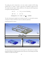
Square profile (50x50x3) - without any substance in the middle
A square profile with the dimensions 50x50x3 is selected for the structure. The dimension
50x50x3 is chosen because it is a standardized aluminum 6082-T6 profile size 17. The tools
inside the RITS will be installed with customized cassettes designed to slide to the operating
position. The cassettes will be guided on "traces" in the structure, and square profiles will
make this guiding easier.
Table 10: Square Profile measurements in millimeters [MN]
Properties
Metric Values
Aluminum area
2,91 cc
Inner area
0,001963 mm2
Weight per meter
7,86 kg/m
- In air
Weight per meter
6,1308 kg/m
- Water
Pressure capacity
~ unlimited as long there are holes in
(depth rating)
Illustration of profile
the profile
Areal Moment 18
7600 mm3
The strength of the structure can be calculated by use of NX and ANSYS. If the profile should
be too weak a second solution of the same profile is presented.
Square profile (50x50x3) - Frame filled with buoyancy (Syntactic Foam)
A profile filled with buoyancy (syntactic foam) will create a sandwich effect between the
upper and lower part of the profile. This kind of profiles is known for being very strong.
Syntactic foam inside the profile makes the structure lighter. The choice between the two
profiles will be determined in chapter 10.1 (Buoyancy) due to need for buoyancy elements.
Syntactic foam may solve the issue by filling the profile; however from an economical point
of view it is not ideal since the process of filling a structure with foam increases the cost.
17
18
(Smith Stål, 2014)
(Johannesen, 2002)
28
4.4
Assembling the structure
There are different ways to assemble a square profile into a structure. Subsea structures are
normally welded together. FMC wanted other options than welding to be considered. Bolted
and welded structures are discussed in this chapter while glue and other assemble methods has
been considered too unsecure/innovative and will not be further discussed.
4.4.1 Bolted structures
The main advantage with bolting a structure is to make it easier to replace broken pieces. The
challenge is to get the structure solid enough. Important concerns for design of a bolted
construction are:
•
A bolted structure needs to be designed in a way that allows the bolts to fasten into the
profiles; since profile is hollowed it will not be possible to fasten bolts on the ends.
•
It is a challenge to bolt the structure in a way that prevents the square profiles to turn
around. They need a fastening system that makes them stay in the same position at all
times.
•
The system needs to provide a solid connection to prevent stress issues as fatigue.
•
The bolt assembly should not increase or decrease the size of the structure.
Figure 23: Example of a skid structure [MN]
The table on next page presents the most realistic bolt connections. They are evaluated
according to the criteria listed above.
29
First idea
Strategy: Make the bolt assembly as similar as possible to a welded solution
Evaluation: To prevent the bolts from spinning custom made cuts in the elements are
required. This ends need a lot welding to be able to fasten bolts.
Conclusion: It requires as much welding as it takes to weld the whole construction.
Bolt Assembly First Idea is REJECTED
Second idea
Strategy: Use the profiles square geometry to prevent spinning - easy to bolt true the sides.
Evaluation: This bolt assembly leads to a higher structure, or a smaller inside.
Conclusion: One of the design criteria was to keep RITS as small as possible. At this point of
the project it is hard to estimate the needed space inside RITS; however it is not a good idea to
let the bolt connection be dimensioning.
Bolt Assembly Second Idea is REJECTED
Second idea
Strategy: Adjust the ends without need for welding - and make it possible to bolt true the
elements.
Evaluation: This bolt assembly method should be cheap to create; however the fastenings
between the elements consist of only 3mm thick aluminum. It is assumed that this connection
will surge which will expose the structure for fatigue.
Conclusion: The fatigue issue is evaluated to unsecure, there is not acceptable to loose RITS
while operating on 2000 meters depth.
Bolt Assembly Third Idea is REJECTED
Table 11 presents some different bolt assemblies, none of them suited for RITS
30
4.4.2 Welded structures
The most common method to assemble a structure is by welding. As the bolt assemblies were
found inappropriate - welding came out as the most ideal assembly method.
A welded structure allows an easier fastening of profiles perpendicular on each other. The
welds are solid and usually stronger than the material in the elements. The welding will
additionally provide a more adjustable geometry than a bolted connection since it is easier to
fasten welded elements in any direction.
Many details on the structure, in addition to joining the elements, require welding. It is details
as fastening of the cylinder and mounting of the instruments inside RITS. Non-destructive
tests (NDT) of all the welded joints are required to control that the welds are properly made.
The NDT methods for weld joints are x-ray or ultrasound, and the documentation that follow
welded joints are more complicated than for a bolt connection.
The documentation is considered a disadvantage of welding since it requires a welding
procedure which is developed by FMC and the operator welding RITS. When the
documentation procedure is developed it can be used for all welds which make the process
smoother.
Welding of aluminum require another technique than for steel which must be documented
through a separate procedure. Except for that welding of aluminum elements is not considered
a problem.
31
4.5
Outer Dimensions of RITS
The "footprint (length and width)" of the structure is decided by the size of the smallest ROV.
The skid should not be bigger than the smallest ROV allows because it will increase the
chance of hits towards the structure. The shortest and less wide ROVs are market in table 1
and result in a skid footprint size of 1550 x 2700 mm. 300 mm is added to the length to make
space for the manipulator.
The skid will be mounted under the ROV with the risk of being exposed to hits from under.
The skid height needs to have enough space for the tool package all the special tools are
installed inside an API 17D interface receptacle. It is assumed that the tools do not need any
more space than the interface receptacle. To be on a safe side a few millimeters are added to
reduce potential complications later on. The dimensional tool height is determined to be
250mm, and the skid structure will build 50mm on both the lower and upper frame. This gives
a total height of 350mm.
The skid's outer frame dimensions is: 1550x2700x350mm
Figure 24: The Structure of RITS [MN]
32
4.6
Strength of structure
There is important to verify that RITS are solid enough to operate subsea, and can handle the
impact load while the ROV will park upon existing subsea equipment. This calculation will be
performed in ANSYS by use of the 3D-model presented in chapter 4.5.
RITS is built by 50x50x3 profiled aluminum 6082-T6, and the model created is fully
compatible for a strengthen analysis in ANSYS. The CAD software needs material strength as
input- which is 250 MPa for aluminum 6082. The model in ANSYS will be market with a
color code if the forces on the structure overstep 250 MPa.
ANSYS does the analysis knowing the structure and material of RITS. However, there is a
challenge to calculate the applied forces on RITS. "Det Norske Veritas" standard, DnV No
2.7-3: Portable Offshore units 19 describe the force that applies on subsea structures.
The forces presented in DnV 2.7-3 are the actual forces added safety factors. The actual
weight of the structure and the landing speed of RITS need to be determined before the safety
factors can be calculated. The most significant weight of RITS is the ROV mounted on the top
of the structure. The figures in table 1.3 inform that a common ROV weigh approximately
5000 kg even though the interface receptacle will be designed with a rubber element on the
end to reduce the impact load. The interface between RITS and the ROV will have some flex
resulting in that the actual "impact weight" is estimated to 75% of 5000 kg.
The landing speed is presented in a FMC document, FMC SPC60099795: Intervention/Tie-In,
ROV Interface Handbook - Design Guidelines 20, based on experiences from previous FMC
projects. . The handbook assumes a realistic impact speed to be 0.5 m/s. The speed combined
with the "impact weight" gives the actual impact force of:
𝐼𝑚𝑝𝑎𝑐𝑡 𝑊𝑒𝑖𝑔ℎ𝑡 = 5000𝑘𝑔 × 0.75
5000 × 0.75 = 3750 𝑘𝑔
19
20
𝐼𝑚𝑝𝑎𝑐𝑡 𝐿𝑜𝑎𝑑 = 𝐼𝑚𝑝𝑎𝑐𝑡 𝑊𝑒𝑖𝑔𝑡ℎ × 𝑆𝑝𝑒𝑒𝑑 × 𝑔
𝑰𝒎𝒑𝒂𝒄𝒕 𝑳𝒐𝒂𝒅 = 3750𝑘𝑔 × 0.5
(DnV, 2011)
(Reinert, et al., 2013)
33
𝑚
𝑠
𝑚
× 9.81 𝑠×𝑠 = 18393N
DnV 2.7-3: Impact load for strength analysis
RITS is a Portable Offshore Unit less than 25 ton and with a "high" risk (ref DnV standard
2.7-3) that makes it a R45 class unit. This risk classification gives the opportunity to calculate
impact forces that can be inserted in ANSYS.
Horizontal impact:
The force that will be the basis towards RITS in horizontal direction is given in chapter 3.6.1
in DnV 2.7-3. The test in CREO will be performed by inserting the calculated horizontal
impact load, FHIR, perpendicular to the structure.
FHIR is the greatest of following factors (see table 5.2 in DnV 2.7-3):
𝐹ℎ𝑖𝑟 = 2.5 × 𝐼𝑚𝑝𝑎𝑐𝑡 𝐿𝑜𝑎𝑑
𝐹ℎ𝑖𝑟 = 2.5 × 18393
𝐹ℎ𝑖𝑟 = 45982 𝑁
𝑜𝑟
𝑜𝑟
𝑜𝑟
𝐹ℎ𝑖𝑟 = 𝐼𝑚𝑝𝑎𝑐𝑡 𝑙𝑜𝑎𝑑 × �1.4 + 0.8 × √(50/𝑀𝐺𝑊� )
𝐹ℎ𝑖𝑟 = 18393 𝑥 (1.4 + 0.8 × √(
𝐹ℎ𝑖𝑟 = 27449 𝑁
50
3750
))
The horizontal impact load will be applied on the front of the structure on one of the longest
elements with a force of:
𝐹ℎ𝑖 = 45982 𝑁 × 0.08
𝐹ℎ𝑖 = 3678 𝑁
Figure 25: Horizontal Impact Load - and impact position (Case 1) [MN]
34
Vertical impact:
There are two scenarios that need to be fulfilled due to vertical impact.
All actual forces are applied at one corner. It is a possible scenario when RITS is put down on
ground. This force is already calculated and is the same as "impact load" = 18939 N.
Figure 26: Force applied from beneath (Case 2) [MN]
The second scenario is similar the horizontal impact (3678 N); however it will be applied to
the weakest point of RITS. The weakest point of RITS is on the longest element, which is one
of the elements going perpendicular on the length of the structure.
Figure 27: Vertical Impact Load on most exposed corner [MN]
Figure 28: Vertical Impact Load on exposed element, Case 3 [MN]
The results from the analyses are presented on the next page.
35
4.7
Strength analysis
Case 1
Stress Max 250 MPa* (Aluminum)
Requirements
No requirements - should be functional
Stress = 21.11 MPa* = ACCEPTED
Deformation = 0.3 mm = ACCEPTED
*= Hot Spot, see Appendix B for explanation.
Case 2
Stress Max 250 MPa (Aluminum)
Requirements
No requirements - should be functional
Stress = 147.5 MPa = ACCEPTED
Deformation = 0.14 mm = ACCEPTED
Case 3
Stress Max 250 MPa (Aluminum)
Requirements
No requirements - should be functional
Stress = 130.8 MPa* = ACCEPTED
Deformation = 2 mm = ACCEPTED
*= Hot Spot, see Appendix B for explanation.
Table 12: All tables is stress and deformation analysis of structure
36
Chapter Five - The Cassettes
The cassettes are an important part of RITS, almost all the capabilities in RITS are in the
cassettes. There are two types of cassettes; one with an API 17D interface and one without the
API 17D interface. The main purpose of the first type is to be able to dock on to subsea
equipment while main purpose with the last one is to provide RITS with loose tools.
There will be designed five different cassettes - all with different capabilities. There is space
for three cassettes on the RITS at the time, so the customer can choose which of the five
alternatives they need for the exact operation.
5.1
Modes of operations
Few systems in the subsea business are module based. Normally there is a new special design
to every project, even if a similar project is developed earlier. The RITS design should be
modified to a system that is more flexible.
All the different tools will be installed in the cassettes and the customer should be able to
choose which tools they need. The manipulator should also be a part of customer package
choice. By defining the cost of each piece a flexible module system is created, and the
customer can pay due to their need; however it is recommended to have the manipulator
installed at all times to maintain the flexibility.
There is only possible to install one
torque cassette and one cylinder
stab cassette at the time. It is
because the control system limited,
it
is
not
enough
hydraulic
components to handle more than
one of these components at the
time.
Figure 29: Cassette Configuration [MN].
37
5.2
The Cassette Design
There are a few design requirements that count for all cassettes.
1. Equal size to fit in the same guiding system.
2. Approximately the same weight - It is an advantage that the people handling RITS can
switch between the cassettes without concerning about the center of gravity.
3. Mounting system - which way the cylinder is mounted
Equal Size
The size of the cassettes is dependent on the outer dimensions of RITS while the size of the
skid was determined by size of the tools. The height was dimensioned to allow space for the
largest tool, the torque tool. The length of the cassettes is slightly increased to make space for
additional buoyancy and also to make the cylinders fit. It results in cassette outer
measurements of 230x360x600.
Equal Weight
The cassettes are designed in the same material as RITS, aluminum 6082-T6, to avoid
galvanic corrosion. The cassettes will be filled with syntactic foam in all hollow areas to make
the cassettes buoyant in water. The plate elements consist of two aluminum plates with room
for syntactic foam in between, the resulting in a sandwich construction that makes the
cassettes both lighter and stronger (see figure 31).
There is not necessarily enough room for buoyancy to make the cassette neutral in water. The
tools inside the cassettes will increase the weight, and to compensate this weight dedicated
areas for extra buoyancy elements are created in the structure - chapter 5.2.1.
The weight and volume measurements of all cassettes are performed in NX - the buoyancy is
calculated in Excel.
Different mounting system
The two different cassette types have different methods for mountening the cylinders and for
fastening to RITS. Cassette type one is fastened on the mounting ears in front of RITS. This is
because type one cassettes will be exposed to the impact load when the ROV parks RITS.
The second cassette type does not have the same requirements due to strength, and they will
not be functional unless the cylinder is mounted in the opposit direction - chapter 5.4.
38
5.2.1 Cassette Buoyancy
The areas in front of the structure where the cassettes are installed will prevent too much
variation of the center of gravity (CoG).
The calculation of buoyancy is the volume of the elements multiplied with the floating
capacity of syntactic foam, the volume is measured in NX, while the calculation is performed
in excel (a document added the source list) 21
The dedicated elements are located over and under the structure in the front. The right
combination of these three alternatives will make the cassettes equally weighted.
Figure 30: The buoyancy elements dedicated the cassettes [MN]
Table 13: An overview of which cassettes and the use of elements
Cassette
"Tool" Cassette
"Holder" Cassette
"Torque" Cassette
"Cylinder Stab" Cassette
"Free Stab" Cassette
#1
1
1
1
1
#2
2
2
-
#3
1
1
-
Weight reduced
-1.9 kg
-10.9 kg
-10.9 kg
-1.9 kg
Weight in air
1.7 kg
10.1 kg
10.1 kg
1.7 kg
The table reveals how many elements the different cassettes will need. It is based on an
evaluation of the weight of the tool combined with the cassettes.
21
Excel: Buoyancy calculation
39
5.3
The Cassettes Type One with an API interface
The cassettes have tracks and holes to make it fit the structure. In front it is hole made to fit
the API 17D interface. On the other side there is a hole created to make room for the
hydraulic and electric lines. The lines connect the cassettes to the structure where the control
units are postioned.
These traces and holes makes it possible to create a standard cassette structure and buoyancy.
Figure 31: Adjustments created to fit the cylinder [MN].
The most challenging customization are the tracks to make the cylinder fit - the cylinder is the
same as presnted in chapter 3. The tracks in the cassette will have extra 75mm applied in the
front to adjust the cylinder to be fastened to the mounting ears in the structure.
The type one cassettes are installed with the interface receptacle to be able to dock on to
subsea equipment. Some of the type one cassettes have additional capabilities because of
integrated tools. Cassettes of this kind have similar structure and a "standard" buoyancy
package.
Table 14: Standard Cassette type 1 - weights
Weight in Air
Weight in
Water
Cassette structure
6.044 kg
3.8 kg
Standard Buoyancy Package
3.3 kg
-3.6 kg
40
Cassette type one is fastened on the mounting ears in front of RITS. This is because type one
cassettes will be exposed for the impact load when the ROV tries to park RITS. The impact
load will be calculated later on; however the design direction of the cylinder used are
explained in the cylinder chapter 3.1.3.
The structure is designed with mounting ears illustrated in Figure 32. The cylinders on the
cassettes are adjusted to fit into those ears. Figure 32 illustrates the first 800 mm in front of
the structure of RITS.
Figure 32: Cylinder mounting ears, cassette type one [MN]
This is the main difference between the two cassette types. Chapter 3.1.3 Cylinder Position
explains the main idea of the placement of the cylinders that will handle the impact load of
parking RITS.
The cassettes type two has other limitations due to strength and functionallity, the reason is
explain in chapter 5.4 - The Cassette Type Two; however the conclusion is a cylinder
mounted in oppocite direction and fastened in the mountings ears behind.
Figure 33: Mounting of cassette type two, note cylinder direction [MN]
41
Torque Cassette
The Torque Tool is hidden behind the buoyancy
elements - figure 33. Behind the foam elements it
looks like presented in the tool chapter (chapter 3 figure 19). The ROV handle is not installed in the
Figure 34: Illustration of the Torque Cassette
[MN]
cassette since there is no need for it, and it will
cause extra weight.
The Torque Cassette is the heaviest of the cassettes, since there is not sufficient space for
buoyancy elements to make it neutral in water. Consequently, it will determine the weight of
the other cassettes
Table 15: Weight of all the components and the total weight of the torque cassette
Weight in Air
Cassette structure
6.044 kg
Tool Weight (ref chapter ___)
39 kg
Standard Buoyancy Package
3.3 kg
Extra Buoyancy
14.6 kg
Structure cassette buoyancy - See chapter 5.2.1* 0
Total Weight
63 kg
Weight in Water
3.8 kg
30 kg
-3.6 kg
-15.6 kg
-10.9 kg
3.8 kg
Figure 24 shows how much syntactic foam that is
possible to fill in the Torque Cassette in addition to
the standard buoyancy package. The volume is
29418040 mm3 which results in a weight in water
reduction of 15.6 kg.
Figure 35: Maximum buoyance possible inside the
torque tool [MN]
The lowest weight possible for the Torque Cassette
will be 3.8 kg. This weight is determined by the
weight of the structure and the tool, in addition to standard buoyancy elements.
It results in an extra cassette buoyancy alternative is implemented that reduces the weight in
water by 10.9 kg.
42
Cylinder Stab Cassette
The cylinder stab cassette is a custom-made solution where the hot stab is installed inside an
API 17D interface. It requires a special design of the hot stab interface on the subsea
installation.
The system works by using an extra cylinder that can push an extended hot stab through the
API receptacle. A guiding system with a rail and tractor is integrated in the cassette to secure
a proper guiding.
Figure 36: The Cylinder Stab Cassette, with all the extra components making it work [MN]
The components needed to push the hot stab, makes this unit similarly weighted as the torque
cassette. The structure is a bit modified which results in a higher weight in addition it results
in a lower buoyancy effect. By using extra buoyancy calculated in chapter 5.2.1 it is possible
to lower the weight in water to 2.4 kg, which is approximately the same as the weight of the
torque cassette.
Table 16: Weight of all the components and the total weight in the cylinder stab cassette
Cassette structure
Tool Weight
Buoyancy in structure
Structure cassette buoyancy - See chapter 5.2.1
Total Weight
43
Weight in Air
6.22 kg
22.52 kg
3.3 kg
0
32 kg
Weight in Water
3.92 kg
13 kg
-3.6 kg
-10.9 kg
2.4 kg
Holder Cassette
The holder cassette will not have any function
except from parking RITS onto the interface
bucket. The structure will still be built in the
same way as the rest of the cassettes type one,
Figure 37: The holder cassette [MN]
with a standard buoyancy package and standard
aluminum profile.
The cylinder underneath has a maximum stroke length of 181mm, which is restricted to only
push the interface out. To be able to get access inside the holder cassette, an extra stroke
length will be required, figure 37 illustrates the problem.
Since stem is pulled completely inside the cylinder housing when cassette edge and the
structure edge are aligned there will be no access to the inside of the cassette. It results in a
cassette that will not be able to carry any tools. The cassette type two is more suitable in cases
where a tray should be required the holder cassette must be installed to provide the API 17D
docking option.
The most likely usage for the holder cassette is when two, type two cassettes are need. The
holder cassette is easy to make buoyant because of the available space inside; however it is
preferable to install the buoyancy in the dedicated structure areas to keep low weight of the
cassette in air.
The extra needed buoyancy should be installed in the structure and not inside the cassette
since it will make the handling of the cassettes on deck easier. It is a strategy that applies for
all the cassettes.
Table 17 Weight of the components and the total weight of the cassette
Weight in Air
Cassette structure
6,044
Tool Weight
8.5 kg
Buoyancy in structure
3.3 kg
Structure cassette buoyancy - See chapter 5.2.1* 0
Total Weight
17.8 kg
44
Weight in Water
3.8 kg
5.3kg
-3.6 kg
-1.9
3.6
kg
5.4
The Cassette type two for Tool Carriers
The main purpose of the cassette type two is to bring special tools subsea. It function as a tray
and will not be installed with the API 17D interface.
The lack of the API 17D interface requires a different fastening of the cylinders. Normally the
cassettes with API interface are in operational mode when the cassette edge is aligned with
the structure edge (the API will then be pushed 181 cm out in operational mode). The same
stroke lengths apply for cassettes type two, and there will be no access of the tools inside. A
different
setup
is
therefore
required
for
the
cassette
type
two
cylinders.
Figure 38: Direction of cylinder due to cassette type [MN]
A simple solution is to mount the cylinder on the mounting ears behind the cassette. The tool
carriers will merely bring tools subsea, and are not designed to handle any impact loads
because they do not have any API interface. As a result, the Cylinder Position presented in
chapter 3.1.3 will not apply for cassette type two.
RITS are designed with two different tool carriers and there is not possible to create a
standard cassette structure or buoyancy profile. The cassette structure will nevertheless be
filled with as much syntactic foam as possible.
45
The "tool" Cassette
Figure 39: Weight of the components and the total weight of the tool cassette [MN]
The tool cassettes have a unique and simple design which is suited for this cassette only. The
aluminum structure is heavier than the other cassettes since there is no need for hole to make
the API 17D interface fit, however it is partly compensated with more space for buoyancy.
There is no tooling other than the structure itself. The cassette weight is 1 kg in water.
Table 18: Weight of all the components and the total weight if the cassette
Weight in Air
7.65 kg
3.5 kg
11.2 kg
Cassette structure
Buoyancy in structure
Total Weight
Weight in Water
4.8 kg
-3.8
1 kg
Free Stab Cassette
Figure 40: Free stab cassette [MN]
The free stab cassette is more customized than the others. The cassette structure is without
any front so it is possible to reach the hot stab. The modified structure requires a different
buoyancy package than the other cassettes, and the structure will therefore be of different
weight.
46
Table 19: Weight of all the components and the total weight if the cassette
Cassette structure
Tool Weight*
Buoyancy in structure
Structure cassette buoyancy - See chapter ___*
Total Weight
Weight in Air
7.0 kg
4.5kg
2.5 kg
0
14 kg
Weight in Water
4.4 kg
3.5 kg
-2.7
-1.9 kg
3.3 kg
A structure dedicated buoyancy element is installed to keep the weight of the cassettes
approximately equal. It results in a weight in water of 3.3 kg which is within acceptable
tolerance compared to the weight of the other cassettes.
In addition the free stab cassette will need more flexible hoses since it will be pulled out by
the manipulator. The manipulator will handle the free stab by pulling it out from RITS and
into the position on the ROV panel, as illustrated in the upper illustration of figure 41.
Hose for free stab
The first idea to handle the flexible requirements of the
hose was to install a hose reel; however a hose reels are
not tested for subsea. To avoid complications with the
reel another system was developed. By installing an
elastic band to the hose it will be pulled back as
illustrated on figure 41.
Figure 41: Hose retrieval system [MN]
The elastic band is connected the hose and will pull the hose in. A disadvantage is that it will
be pulled back if the manipulator loses its grip. The advantage is that a system like this is not
woundable for deep water.
47
5.5
Hose - Cassette hydraulic supply 22
All the cassettes will be moved from operational to transport mode several times, to allow
such a system a flexible connection of hydraulic hoses will be required. Hoses are normally
strong with respect to pressure from inside, however hoses have a tendency to collapse if the
external pressure gets much higher than the outside pressure. Hoses applicable for 200 Bar
external pressure is quite stiff because they consist of several layers of steel.
The hose recommended from TESS Kongsberg was the TESS 5040. It meets all the
requirements for the RITS. It handles external pressure of 200 bar, internal pressure of 300
Bar and it is capable to supply enough flow. The only challenge with this hose is the
minimum bend diameter of 360mm. The bend diameter is demanded to ensure that the hose
will not break, and the diameter will be central in the flex system required for the cassettes.
𝐹𝑜𝑟𝑚𝑢𝑙𝑎 𝑓𝑜𝑟 𝐶𝑖𝑟𝑐𝑢𝑚𝑓𝑒𝑟𝑒𝑐𝑒 = 2𝜋𝑟
360
𝐶𝑖𝑟𝑐𝑢𝑚𝑓𝑒𝑟𝑒𝑐𝑒, min 𝑖𝑛𝑛𝑒𝑟 𝑐𝑖𝑟𝑐𝑙𝑒 = 2𝜋 𝑥 �
� = 1155 𝑚𝑚
2
Extra length needed is 200 mm which is the length the cassettes will move.
𝑥
𝑀𝑖𝑛 𝐷𝑖𝑎𝑚𝑒𝑡𝑒𝑟, 𝑜𝑢𝑡𝑒𝑟 = 1155𝑚𝑚 + 200𝑚𝑚 = 2𝜋 × � � = 431 𝑚𝑚
2
The figure shows the principle to achieve flexible hydraulic
lines. By letting the hose move freely between the guiding
"walls" the hose will be able to move 200 mm without any
stretching. The stiffness in the hose will ensure a controlled
movement - which means that the hose will increase or
decrease it diameter in a secure way. The guiding system will
be installed in an enclosure built up of two gratings and side
Figure 42: Example of guiding
system of flex hoses 200mm [MN]
walls where the hose freely may move and bend. The hose will
be protected with an outer wear-protection from TESS.
Figure 43: Guiding of the hoses will be arranged between two gratings [MN]
22
(Foss, 2014) and TESS catalogue 2014
48
Chapter Six - Manipulator
Titan 4 is a recommended manipulator from Schilling Robotics. Schilling Robotics is the
main supplier of manipulators for the subsea industry, and the Titan 4 is their most successful
invention. The control unit is inside the manipulator it only require power and signal cables
connected to be able to operate Titan 4 is the natural choice of manipulator for the RITS
Mechanical Data 23
Length
1922mm
Width
Diameter
Weight in Air
100 kg
Weight in Water
78 kg
Hydraulic Data
Pressure
207 Bar
Flow
19 lpm
Fluid, oil
Shell Tellus Oil 32
Filtrations
3 microns (10 microns absolute)
Electric Data
Input Power
24 VDC
Power consumption, incl. solenoid 6W start, 12W run
Slave arm current draw
1.875A, at 24VDC
General Data
Max Water depth
4000 meter
Table 20 Data for Titan 4
The Titan 4 will be installed on the top front of the RITS. The manipulator will during
transport be in a position where the ROV protects the manipulator from direct hits.
Kinematics for Titan 4
23
(Schilling Robotics, 2012)
49
Figure 44: Measurement of Titan 4 [Source 24]
Table 21: Kinematics for Titan 4 - 6 revolute joints and joint lengths
24
Link 24
ai
αi
di
ϴi
1
121 mm
п/2
195 mm
ϴ1*
2
851 mm
-
-
ϴ2*
3
483 mm
-
-
ϴ3*
4
133 mm
- п/2
-
ϴ4*
5
-
- п/2
-
ϴ5*- п/2
6
-
-
193.0mm +74.0 mm
ϴ6*
Source: Robotics book
50
6.1
Kinematics, Visual Components and Python Programming
The main challenge to operate a manipulator automatically is to create an expression between
the angles in the joint and the coordinates in the 3D-space. The manipulator-gripper will get
the information to move to a given coordinate; however the issue is what joint angles that give
these coordinates.
Each joint will need a separate angle - and to make it a bit harder - there are several different
angles that can achieve the same coordinate for the gripper at the end.
6.1.1 Kinematics
The tools solving these problems are called forward and invers kinematics. To avoid going
deep into this expressions, a simplified explanation is considered enough for this study. Here
only the principles are briefly described, as the software are fully developed and delivered
with the Titan 4, and a RITS operator will only be an ordinary user.
The forward kinematics needs an input of the angles in all joints at every time step. The
forward kinematics output is the grippers position in 3D space, represented by a [4x4]-matrix
that gives the rotation and position.
It is possible to interpolate a [4x4] matrix, and when the interpolation is executed it is possible
to add a value to the existing [4x4]-matrix. This new matrix is the first step on the way to the
end position. Inverse kinematic will then produce new joint angles and the manipulator
moves. The joint angles are presented as a [6x1] vector.
Forward kinematic will produce a new [4x4]-matrix and a new interpolated value can be
added. By performing this process enough times the manipulator will finally be at the end
position.
Figure 45: Kinematics explanation of the robotics [MN]
51
6.1.2 Visual Components
Visual Components (VC) is the software that performs the kinematics calculation. In addition
to the calculation it has a good application to illustrate this. VC will be able to give the Titan 4
all its needed joint angles to complete a movement. VC has a database for a number of
different manipulators; however Titan 4 was not included in this database. The Titan 4 what
to be implemented manually, which required a new geometric model, new kinematics and so
on.
The picture in figure 46 is capable to simulate the whole operation, and by adding the subsea
unit in the figure it is possible to illustrate exact operations in detail.
Figure 46: Screen shot of Visual Components
1
Is the function that defines the point the manipulator should move to. A new point in the
movement are set by manually move the manipulator to the wanted position and then push
the #1 button and a new point in the movement of the manipulator is created.
2
Illustrates the point that the manipulator shall pass through during the programmed
motion.
3
The kinematics are presented in box #3. The values in this box can be programmed in to
the Titan 4 software, and the manipulator is then ready for a new step/movement.
52
6.1.3 Python
The biggest challenge to make a fully working Titan 4 in VC, was to implement the
kinematics. New kinematic was created for similar manipulators as used in VC and in the
NTNU course TPK4170, “Robotteknikk”. The coding was done in Python, and the software
for the manipulator is able to calculate the joint angles and the end-effectors position.
The kinematics seems to work and the coding is shown in Appendix D.
6.1.4 Example of robotics on a RLWI-stack
The illustration application in VC is a useful tool to present robotics and its abilities. As an
example video simulation of the RITS working with a UR5 manipulator is presented.
The video may be found in the source folder following this thesis. It is called:
UR5 simulation - RLWI-panel
Figure 47: Simulated example in VC
53
Chapter Seven - Hydraulic System
RITS has two hydraulic systems because of stricter requirements of clean fluids into a XT.
This demands a separate system since the fluid the ROV provides does not meet such
requirements. RITS is powered from the ROV’s auxiliary valve pack, which is called dirty
valve pack. Most tools are able to operate on "ROV-Fluid"; however an extra filter is often
installed to reduce the wear on the systems. The fluid supplied from the ROV is in most cases
ordinary hydraulic oils as e.g., very often a Tellus oil from Shell, and the "dirty" fluid side is
therefore often by slang called Tellus hydraulic side (at least in within the FMC).
The clean system is driven by a motor-pump solution, which avoid the fluids from being
mixed. The "dirty" system powers a motor, and the motor is interconnected by a shaft and a
coupling to the pump shaft of the clean system. This system is called Hydraulic Power Unit
(HPU). The fluid that runs in the HPU system depends of what kind of system the tool e.g. a
hydraulic hot stabs, is specified to operate with. It is usually specified oil and can be mineral
oil as well as water based oil.
Tellus (32) oil 25
Viscosity: 32 sST
Density 900 kg/m3
Clean Fluids
The main reason to use mineral oil is to make XT stay subsea for 20 years. To meet these
demanding conditions there are strict requirements for these systems, and where especially the
solenoid valves demands clean fluid. To avoid problems as bacteria growth inside the control
units a mineral oil are demanded.
There are several different types of mineral oil that varies due to supplier of the XT; typically
mineral fluid frequently used is Oceanic HW443.
25
(Shell, 2008)
54
Hydraulic Schematics 26
Figure 48: Schematics created in Visio [MN].
7.1
Note! The check valves on the hot stab are not implemented in this drawing. See Appendix A
26
Hydraulikk bok
55
7.1.1 Valves used in the RITS Schematics
The schematic reveals the components that will make RITS work. The electric power, control
signals and the hydraulic power are provided by or transferred through the ROV. The
electrical power and signals comes from topside through the umbilical to the ROV, while the
hydraulic power comes from a tank in the ROV. RITS will not consume any fluid, since the
system is a closed circuit and cause of that return all fluid taken from the ROV.
Solenoid Valves
A solenoid valve is a control valve for the hydraulic lines that activates the cylinders or the
special tools. The solenoid valve best suited for subsea use need to handle high external
pressure and have the ability to be reliable operated from the surface, maybe 2000 meters
away.
Figure 49 is illustrating how a solenoid is working. The figure to the left is showing the
solenoid valve in normal position. There are springs on each side of the solenoid valve forcing
the cylinder in the "normal" position when the solenoid not is powered. When electricity is
put on the solenoid valve will overcome the spring force, and the core with the valve openings
will move. By putting on electricity on the right side the fluid will circulate in a direction that
extends the cylinder (picture in the middle). If the stem of the cylinder shall be pulled back,
electricity on the left side is put on. Then the circulation will turn the other way and close the
cylinder.
Figure 49: 4-3 Solenoid valves spring loaded [MN]
56
4/3 solenoid valve
A 4/3 solenoid valve means a valve with 4 ports that has 3 different position - like the
solenoids presented in figure 49. This kind of solenoid is suited to handle double acting
cylinders and hot stabs.
Wandfluh BM4D32-G24-M55-M35 27 is the solenoid valve that will be used inside RITS. It
is a 4/3 spring-electric valve. In the normal position (like it is drawn in the schematics) it is
closed, but if an electric voltage is applied the valve switches over and a circulation starts. If
power is lost the springs will force the valve back to closed position. It is a contingency mode
- and the hydraulic flow stops.
A simplified version of the BM4D32-G24-M55-M35 is used for the locking dogs. This kind
of valve is a 4-2 spring solenoid valve. The 4-2 solenoid valve is used in situations where
there are no need to change the direction of the flow. The spring inside the locking dog
cylinder will force the locking dog back.
Figure 50: Picture of solenoid valve: Solenoid operated spool valve.
Figure 34 shows what a single valve look like, while figure 36
shows the function principle of the same solenoid. There are
several solenoids, and to protect them they will be placed together
inside a valve pack as illustrated in figure 35. Installing them in a
row inside a valve pack makes it easier to design the control
system for the valves.
Figure 51: Drawing from previous FMC project
[FMC]
27
(Wandfluh, 2006)
57
The main reason to pick the BM4D32-G24-M55-M35 is because of the ability to handle the
external pressure at 2000 meters depth. Figure 52 illustrates two different 4-3 spring loaded
solenoid valve. Both valves have the possibility to control the direction of the flow in addition
to equalize the flow.
Figure 52: Wandfluh BM4D32-G24-M55-M35 (Schematic) on the left [MN]
The BM4D32-G24-M55-M35 is more suited to handle the pressure at 2000 meters depth
because of the way it stays in neutral position. This kind of valve keeps the cylinder in
position by applying the same flow and pressure on both sides of the piston. The result is a
fully compensated system. The left illustration on figure 36 will not provide the cylinder with
a “auto” compensating system as leakages may result in that the piston moves uncontrolled,
which is a major problem to handle on 2000 meters depth.
The cylinder illustrated below requires a compensating system and that makes the BM4D32G24-M55-M35 the best choice of solenoid valve.
Pressure Relief Valve 28
The pressure relief valve is installed to protect the system
for pressure peaks. The valve is connected the return line,
and when a peak appear it will open and drain the
overload.
This valve will open a line from the supply line to the
Figure 53: A pressure relief valve [Source 28]
tank if the pressure gets too high and the system is
protected. The relief valve installed on the HPU side of the system has a more active function.
The valve will open as long as the hot stabs are closed. See more information in Appendix A Hot Stab.
28
(Wandfluh AG, 2012)
58
7.2
ROV hydraulic system (Tellus system)
The Tellus system of the RITS is powered from the ROV. It is the main power system for all
components in RITS; however it is not clean enough to risk spill of fluid into the other
hydraulic systems.
The "Tellus" system of RITS is the part that can operate with the same fluid as the ROV. It is
units as the cylinders, the torque tool (require a RCU - remotely control unit) and the Titan 4
manipulator. The hot stab system is the only component that needs cleaner fluid. The hot stab
system is operated by a motor on the "Tellus" side of the hydraulic system. The motor powers
a pump that makes the clean fluids run. Systems like this are called a Hydraulic Power Unit
(HPU), and ensure that the fluids are not mixed.
All the systems inside RITS are dimensioned to handle a pressure of 207 Bar. The
components are more different when it comes to flow demand. The flow represents the speed
of action, and the unit with the lowest flow capacity will be the dimensioning. A result is that
some units may become a bit slower - yet the work will still be done since the pressure which
represents the strength is the same.
The system will have its own compensator to protect RITS if the compensating system inside
the ROV fails. A filter is installed as a precaution to avoid unnecessary dirt in the RITS
system.
7.2.1 Filter 29
As for all the components the external pressure at 2000 meter depth is the first demand to be
fulfilled for the filter. In addition a 3 micron filter is needs to clean the fluid to meet the
manipulator demands.
Pall Norway recommended a filter called 9050. The filter 9050 can handle pressure from both
outside and inside up to 700 bars, which is a lot more than needed. Pall is a large supplier of
subsea filters, and is frequently used by FMC for other subsea projects. Of standardization
reasons within FMC, they are the chosen supplier for filters also for RITS.
29
(Pall Corporation, 2002)
59
Contingency solution for the filter
The filter will after a period of time be filled with dirt, and reduce the performance of the
RITS. If the filter should be clogged between service intervals, Pall has provided a bypass
system that opens when the flow cannot pass true the filter. The contingency system for the
locking dogs makes sure that the RITS always will be able to disconnect, and turn back
topside to clean the filter without expose the system for danger. This contingency system and
a regularly access of maintenance makes the bypass system unnecessary. To reduce the risk of
clogged filter it will be cleaned regularly, maybe as often as between every RITS operation.
Figure 54: Picture of pall 9050 taken from the datasheet provided from Pall [source 29]
The exact model is called 9050SKH - where the H specifies the fluid that the filter will clean.
A Pall 9050 filter cleans the system to at least 3 microns and handles 700 bar inner and outer
pressure, and meets the requirements for the RITS.
60
7.2.2 The compensator 30
The compensator on the "Tellus" side of the RITS’ hydraulic system will compensate the
fluid volume variations for all the components. A compensator is a tank that adjusts the
volume by use of a spring and because of that equalizes the pressure when the fluid
consumption of the tools etc. varies. Other volume variations are caused by change of volume
that occur due to change of temperature and change of external pressure.
The compensator principle is a simple, but it is still challenging to calculate the size of the
compensator. In addition to handle the variations of the fluid volume due to physical changes,
the calculations also must include the variations of fluid consumed during operation (works
like a fluid reservoir). Consumption is typically fluid needed to handle the cylinders. The
cylinder consumption is related to different volume on each side of the piston.
The hydraulic system is completely filled when RITS is lowered in the water, which includes
the fluid lines. Since the hydraulic lines are not yet designed an estimation of volumes of the
lines are made based on experience from previous FMC projects. In the calculation for the
RITS compensator length of 4 meter and an inner diameter of 4 mm is estimated. The RCU
has its own compensating system and does not need any extra expansion option, while the
Titan 4 needs an extra volume of 2.2 liters.
Figure 55: Explanation of compensator volume estimation Excel [appendix C] [MN]
30
(Kystdesign, ?)
61
The Excel-Sheet in figure 55 shows the compensator volume calculation. By implementing
the cylinder data it is possible to calculate the difference in fluid consumed for the cylinder
when it is pulled in versus pulled out.
The calculation is made in an Excel datasheet, which is added in the source list. The result
reveals a required compensator volume of 5.85 liters. Kystdesign has a compensator of 6 liters
active volume, which fits the demands for the RITS.
6 liter compensator
Length w/sensor
588 mm
Width
Ø246mm
Weight, air
11.3 kg
Weight, water
estimated 7.2 kg*
Material
POM
Figure 56: Data and picture of the compensator [Source 28]
7.2.3 Valve Pack#2 valve pack for the dirty system
Since RITS consists of two separate hydraulic systems it contains two valve packs. To make
the system less complicated it has been decided that each system will have its own valve pack
to avoid contamination of the cleanest system. The valve pack on "Tellus" side will handle the
solenoids that operate the cylinders. The RCU and Titan 4 have integrated hydraulic control
system from the suppliers, which are connected to a valve pack on Tellus side built up of:
4 pcs: 4-3 Wandfluh BM4D32-G24-M55-M35: 3 pcs are to
activate the trays, while the last is installed to handle the cylinder
stab cassette.
1 pcs: 4-2 Wandfluh: to activate locking dogs in the API 17D
62
Figure 57: The valve pack two with 5
solenoids [FMC]
7.2.4 The hydraulic motor 31
The motor is installed provide the HPU-side with power to run a pump to avoid contamination
of the clean fluid. HPU systems are developed in many different versions where clean fluids
are required. The HPU system used inside the RITS is custom made for the RITS; even if the
principle is taken from previous FMC projects.
One of the most common motors for HPU system in use is the Parker F11. The Parker F11
handles pressure over 207 bars, in addition to be able to supply RITS with the needed flow. It
is a great advantage that it is small, and that it is used subsea before.
Model: F11-010
Max Pressure:
305 bar
Displacement:
9.8 cm3/rev
Flow max:
110 Bar
Max rpm:
10200
Max depth: used subsea when
connected a compensator system.
Weight in air:
7.5kg
Weight in water:
Figure 58: Picture of a F11 Motor/Pump
[Source 31]
31
(Parker, 2013)
63
Determination of the motor size
The F11 is developed in six different sizes. The capacity of the motor is depending of the flow
on "Tellus" side of the system. It is an advantage that the motor is not working at max speed
at all time to reduce wear and tear. The larger motors will give the same volume and pressure
to a lower speed than the small motors. To select the most suitable pump, it will be a trade-off
between low speed and low weight - which is two abilities that work against each other.
The flow on the "Tellus" side of the hydraulic system is dependent of the component with the
lowest max flow. For the RITS it is the manipulator that needs a flow of 19 liters per minute
(lpm). It results in a total system requirement of approx. 20 lpm. When the flow is given it is
possible to pick the most suitable pump size.
Figure 60: Volumetric efficiency [Source. 31]
Figure 59 : Basic formulas for hydraulic motors
[Source: 31]
RPM is calculated by the formula in figure 60. Table 22 represents the results of the
calculation. In the table it is possible to choose the most suitable motor.
Table 22 Abilities for Parker F11 motor sizes [Source 29]
F11- (size)
-005
-010
-012
Weight
4.7 kg
7.5 kg
8.2 kg
Displacement
4.9 cm3/rev
9.8 cm3/rev
12.5 cm3/rev
Flow
20 lpm
20 lpm
20 lpm
Volumetric effectiveness
Assumed 0.97*
Assumed 0.965*
Assumed 0.96*
RPM
3959 rpm
1969 rpm
1536 rpm
*See figure 30: A shaft speed of approx. 2000 rpm is assumed - the small motor will produce a higher RPM on
20l/min, it results in a higher volumetric effectiveness.
The smallest pump works at too high speed to stand required wear resistance. The biggest that
are calculated works at a lower speed, which decreases the volumetric effectiveness. As a
result too much power is lost.
From these considerations the most suiting motor is the F11-010 with a weight of 7.5 kg.
64
7.3
The Clean system - HPU system
The clean hydraulic power unit is necessary to make RITS capable to work with hot stabs.
Many subsea installations are installed with hot stab interfaces to power up a motor or
override a valve etc, where the fluid used for the hot stab gets in contact with the fluid of the
subsea fixed installation. All these systems have different tolerances for cleanness of fluids,
and they are usually significant stricter than a Tellus oil and a 3 microns filter. The “clean” oil
must also be compatible with the oil in the subsea installation.
To control the cleanness of the system a separate reservoir is needed. By installing a
compensator on the HPU side of the system two issues are solved. In addition to handle the
change of volume of the fluid, it applies an extra fluid reservoir. The clean fluid can be filled
into the system before the operation subsea starts, and because of that the customer will have
completely control of the fluid, type and cleanness.
7.3.1 The Pump
A motor uses the hydraulic flow to power a shaft, while a pump circulates the fluids by use of
the power from the shaft. As the same calculation applies for the pump it will be an advantage
to use the same pump as the motor.
The RPM is given in table 12 (=1969). By using the formula for q in table a flow for the HPU
side is given.
The flow on the HPU dirty side of the system has a flow of 18.6L
Figure 61: Pump formulas from the Parker catalog
(Source 31]
65
The coupling between motor and pump
It is difficult to mount the shafts exactly aligned. The misalignment will expose o-rings and
seals for forces and tear. Figure 62 illustrates the effect. To decrease the tear a flexible
coupling will be installed between the shafts, to reduce the alignment problem. A flex
coupling makes also service easier. If one of the parts, either the pump or the motor, has to be
taken out, the other may stay by only dismounting the coupling.
Figure 62: Shaft connection between the motor and the pump [MN and Source 31].
Flex coupling32
Huco Dynatorc is a common flex coupling suited to connect two shafts together. There is no
air filled chambers in the construction, and it is made of aluminum - which reduces the
chances for galvanic corrosion.
Material
Max rpm
Max torque
Temp range
Aluminum
5000 rpm
140 Nm
-40 - 140 ˚C
Figure 63: Huco, multibeam - aluminum
[Source 30]
32
(Huco Dynatork, 2013?)
66
7.3.2 The clean side compensator
The compensator in the HPU has two important purposes. It needs to compensate the external
pressure on the clean fluid system and contains the extra fluid needed to operate external
subsea units by use of hot stabs.
RITS is designed as a tool carrier for many different projects. It makes it challenging to
calculate an exact volume for the compensator. In most cases all fluid are transferred back to
the RITS through the return lines; however mineral and water-based fluids are sometimes
accidentally released to sea. Assuming that all the fluids usually will be returned to RITS,
gives the minimum capacity of the compensator. Another assumption is that powering up a
pump or motor will not consume any fluid. The fluid will first of all be consumed when the
hot stabs overrides subsea valves. By evaluating the most common valves used for subsea
installations it is possible to calculate a dimensioning volume.
Table 23: Summary over consumption of fluids required to operate/override a system
Component
Volume used/
Displacement
Motor
0
1/2" valve
0.016 L
2" valve
0.61 L
7" valve
0.93 L
Explanation
No consumption of fluids to run a motor, since all the
fluid will be flowing back to RITS.
Displacement volume for override (different volume
between each side of the piston)*
Displacement volume for override (different volume
between each side of the piston)*
Displacement volume for override (different volume
between each side of the piston)*
Source
33
34
35
*the displacement volume for an actuator is often the difference of the actuator stem on the stem side of the piston. In
an override situation the return fluid will flow into RITS, and the only fluid consumption is the volume of the stem on
stem side of the cylinder.
One of the subsea installations RITS will handle is the Riserless Light Well Intervention stack
(RLWI- Stack). For the RITS the capacity of this operation is used to calculate the capacity.
The RLWI-stack has two 7" valves, four 2" valves and two 1/2 valves.
In addition some spare compensator volume is added, to handle e.g. failures that cause
leakages etc. a 7" valve will flush 7.4 liters.
33
(FMC Technologies, 2002)
(FMC Technologies, 2006)
35
(FMC Technologies, 2007)
34
67
Compensator volumes
A similar excel sheet as the one presented for the "dirty" side is set up for the compensator
volume on the "clean" side of the system. The calculations estimate a compensator volume of
7.45 liters, but without any spare capacity for failures. It means that one 6 liters compensator
as used on the Tellus side is too small.
There are larger compensators than 6 liters; however there could be an advantage to keep
compensators of equal size. Knowing that the reservoir will be empty by one flush to sea by
the 7" valve there is desirable to increase the reservoir with a few liters. Installing two 6 liters
compensator provides a volume of 12 liters - which seems like a satisfying volume for RLWI,
and many other subsea projects.
It makes it possible to keep the operation going even if some fluid is lost by one flush to sea.
The estimation is not accurate, however there is difficult to make exact volume estimation for
a random project.
Figure 64: Compensators placed in a rack [MN and source 30]
Compensators of equal size can be installed in a rack which is easier for the people that shall
assemble RITS.
68
7.3.3 Valve Pack
The valve pack on the HPU side of RITS hydraulic system has nine valves of the same; ref
figure 66. The nine Wandfluh BM4D32-G24-M55-M35 controls three hot stabs. Each hot
stab requires three valves. One valve to each pair of line, and since the 3 position solenoid
valves handles one supply and one return line there are only three valves needed.
The three first valves on the figure are planned for a spare hot stab (if the customer wants
three hot stabs), and valve four to six is connected the second stab. The last three valves are
installed to supply the main hot stab with hydraulic.
Hot Stab 6L 36
Figure 65 illustrates the three solenoids required
to operate one 6L hot stab. RITS will have the
possibility to handle three hot stabs, and as a
result the valve pack will have nine solenoid
valves. The system is explained in Appendix A.
Figure 65: Schematic of a standard hot stab [Source 36]
Figure 66: Copy of Schematics [MN]
36
(FMC Technologies, 2010)
69
Chapter Eight - Control Unit
The previous chapters have presented components needed to make RITS work. The hydraulic
system is designed; however a system that controls the hydraulic system is required. This
chapter will explain how the RITS will be controlled by use of telemetry and other
communication components.
7.1
Valve pack - Control Systems 37
A valve pack is custom designed RCU for the rest of the system in RITS, except for the
torque tool. The solenoid valves are positioned in a row with a control card (PWM16) on top.
This control card is called an embedded control unit, and controls which solenoid valve that
will opens the hydraulic line.
•
The control card will send an electric signal to a
spring force in the
magnet that will overcome the
solenoid.
•
The solenoid valve will only open the hydraulic line
•
The electricity and the hydraulic lines will at all times be connected to the valve pack,
just waiting for signal to be activated.
Figure 67: Picture of a valve pack from Innova [Source 37]
37
(Innova, 2014)
70
that it is connected to.
7.1.1 PWM16 - Control Card 38
The signals from the computer topside will end up in the PWM16. This is the unit that applies
power to the solenoids valves that opens the hydraulic lines. The hydraulic system will be
active at all times, and the control card will decide what line that is open. The solenoid valves
presented in chapter 7.1.1 allows the flow go in both direction, which means one line to
supply and one to tank/return. It signals are sent to the other side of the solenoid valve it will
switch and the circulation will go reverse direction.
This is how the operator can control the cylinder to
go out or pull back in.
The PWM16 operates 16 individual 24 VDC loads.
It means that one PWM16 operates eight 4-3
solenoid valves.
It has a depth rating on 3000 meters and
communicates with both a RS-232 and a RS-485
Figure 68: PWM 16 [Source 38]
standard.
7.1.2 Titan 4 - Control system 39
Titan 4 is an advanced system with the control card integrated inside the manipulator.
However there is an issue to be customized as the control card needs a communication board.
Figure 69: Control card for Titan 4 [Source 39]
38
39
(Innova, 2014)
(Schilling Robotics, 2012)
71
7.1.3 CUTE - Communication Distribution Board 40
The system will have several PMW16 control cards. A master communication distribution
board (CDB) is required. The CDB supplied from Innova can handle four different control
cards, which is exactly the number of PWM16’s and Titan control card on the RITS.
Size:
160x100x12mm
Electrisity:
12DC (24VAC optional)
Telemetry:
1 off RS-232 or 4 off RS-485
Figure 70: CDB from Innova [Source 40]
It is designed to be installed in an enclosure without any depth rating. Instead of designing a
special container for the CDB, it is planned to integrate it in an electric transformer package.
7.2
Electricity Can
All the control cards, solenoid valves and the distribution board require 24 VAC. Installing a
transformer will make the system less complicated since it reduce the customization of all the
control units. Innova has developed systems like this earlier; however there is not a standard
product. This unit will be customized by Innova due to the system requirements.
Table 24: Electric Can [Source: FMC - Per-Olaf Tangen]
Weight in air:
Weight in water:
Material:
Interface:
Power input:
Power output:
Power rating
11 kg
2.3 kg
Aluminum 082-T6, Hard
Burton 5506-2008
88-264 VAC, 47-63 Hz
24 VDC
500W
The info given on the transformer is taken from a previous FMC project. The power input has
a wide range which makes it compatible with the RCU’s. In addition to make the system less
complicated it will contain the CDB to protect it from the external pressure.
40
(Innova, 2014)
72
7.3
RCU - Remote Control Unit 41 for the torque tool.
The RCU described here is installed when the torque cassette are needed. The torque system
is an Oceaneering product. The RCU is the control unit for the torque tool, and is delivered
with control HMI software. It is the kind of system that will be designed for the rest of the
components; however the RCU will only be able to control the torque tool inside the torque
cassette while the other system needs to operate several units.
RCU facts:
Depth rating: 3000 meters
Max Pressure: 250 bar
Max flow 95 lpm
Weight in air: 30 kg
Electricity:
90-132 VAC.
Telemetry:
RS-232 or RS-485
Figure 71: Model of the RCU from the OMM [Source 41]
This system requires separate signal and power lines to be able to operate. The hydraulic will
be supplied from RITS (on the Tellus side). The configuration of the RITS will ensure that the
RCU will be compatible with the other systems due to signal and electricity, but even so it
will require separate lines.
7.4
Control system Hierarchy
The RCU of the torque tool has its own system, while the rest of the control units will be
controlled through the CDB placed in the electricity can. A consequence is that two signal
lines and two electric lines are required when a torque tool is installed.
Figure 72: Hierarchy of control units [MN]
41
(Oceaneering, 2009)
73
7.5
Signal
The CDB is capable to handle four control cards as long as the signal is RS-485. RS-485 is a
protocol to handle signals. The CDB will communicate with one master signal transfer
to/from topside. Signals sent to the CDB are transferred further to the PWM16’s that operates
the solenoids.
Table 25: Signal configuration
Valve
DC1
DC2
DC3
DC4
DC5
DC6
DC7
DC8
DC9
DC10
DC11
DC12
DC13
DC14
Tool
Lines
L11
L12
L21
L22
L31
L32
L41
L42
L51
L52
L61
L62
L71
L72
L81
L82
L91
L92
L101
L102
L111
L112
L121
L122
L131
L132
L141
L142
Valve
pack
#1
#1
#1
#1
#1
#1
#1
#1
#1
#2
#2
#2
#2
#2
Component
Function
1st Hot stab spare
1st line t/r
1st Hot stab spare
2nd line t/r
1st Hot stab spare
3rd line t/r
2nd Hot stab spare
1st line t/r
2nd Hot stab spare
2nd line t/r
Supply A - Drain B
Drain A - Supply B
Supply C - Drain D
Drain C - Supply D
Supply E - Drain F
Drain E - Supply F
Supply A - Drain B
Drain A - Supply B
Supply C - Drain D
Drain C - Supply D
2nd Hot stab spare
Supply E - Drain F
3rd line t/r
Drain E - Supply F
3rd Hot stab spare
Supply A - Drain B
1st line t/r
Drain A - Supply B
3rd Hot stab spare
Supply C - Drain D
2nd line t/r
Drain C - Supply D
3rd Hot stab spare
Supply E - Drain F
3rd line t/r
Drain E - Supply F
Hot
Stab
API Activate hot stab
solution
Pull back hot stab
1st cylinder
Activate Tray #1
Closes Tray#1
Activate Tray #1
Closes Tray#1
Activate Tray #1
Closes Tray#1
Locks RITS to buckets by use of locking dogs.
Releases RITS
2nd cylinder
3rd cylinder
Locking dogs
The table shows the signal list for the RITS.. This table is the basis from where a control
screen and the software for the control system is created.
74
Chapter Nine - Graphic User Interface
The GUI (also called HMI) is the screen that allows the operator to send information to the
control system. The panel built up of switches that will open or close hydraulic lines that
activate the hydraulic lines and the operation given in table 25 will be done.
A GUI for the RITS is shown in fig 73. The Configuration section of the control screen panel
is installed to make the system flexible. It is a “tick off” selection system that will activate
other panels the will pop-up to the right. The switches will be grey until the box on the
configuration panel is “ticked off”. It is important that the “tick off “reflects the current tool
equipment of RITS, if not the HMI will activate wrong lines. This has to be tested and
checked on a test stand before RITS goes subsea.
The manipulator and the RCU have their own system. By push their buttons a new HMI
picture will appear - and is the suppliers HMI. If there is enough screens topside, the
manipulator should have its own HMI active at all times.
Figure 73: Concept drawing of the HMI [MN]
75
The Upper right left panel controls valve pack two (DC10-DC14 in table 25). There are five
switches that allow the cylinders and the locking dogs to be operated. The locking dog system
will activate the dogs in all three interface receptacles; however if one of the cassettes are
installed without API 17D interface the hydraulic line will be installed with a blind flange.
This blind flange is mounted topside when the cassette configuration is installed.
Lower panel controls valve pack one (DC1-DC9 in table 25). The switches will open a
supply line and a return line in one of the hot stabs. Which one is depending of what the
operator want. It will be tested onboard of the vessel to avoid wrong couplings etc.
Sensor panel (upper right panel) is installed to be able to monitor the system. There are
important to know the status inside the skid when it is in operation. In addition to prevent
damage, it may reveal the reason for any malfunction. The RITS and the tools are expensive,
and therefore a panel showing the system status will be required to manage a safe and secure
operation.
9.1
Sensors
The numbers of sensors that are required inside RITS are limited. In addition to monitor the
level in the compensators, it is important to know the pressure on both sides of the hydraulic
system (dirty and clean). The flow is also an important factor to monitor, and the motor has an
opportunity to install a shaft-speed transducer, This makes it possible to calculate the flow on
both sides of the hydraulic system. The last transducer that is required is a temperature
transducer to make sure that the motor will not break. The temperature in the motor cannot
exceed 80 degrees.
9.1.1 Sensor Signals to surface
The sensors will be connected to the PWM16 installed in valve pack 1, and the signals will be
routed true the CUTE and up to the hardware topside (HMI). The position of the sensors
varies - some components are developed with sensor-possibilities while other sensors needs to
be installed on the piping, or custom made flanges.
Each PWM16 can handle five sensors, and there are two of them in valve pack 1. It is
preferable that the sensor signal is 4-20 mA.
76
Fluid Level Sensor
The 6L compensators from Kystdesign are delivered with a level sensor integrated. To
activate the sensor a signal coupling to the PWM16 will be required.
Speed Sensor
The motor is the most charged component, and needs monitoring. The
motor has an option for mounting a speed sensor of the shaft. This sensor
is useful since it also makes it possible to calculate the flow of the
hydraulic oil in the clean and dirty system (by use of the formulas
Figure 74:
[Source 31]
Speed
presented in chapter 7.2.4 and 7.3.1).
Pressure Sensor 42
The pressure sensor is essential to have control over the
system and to alert failure. A pressure sensor in front of
the motor is required to be able to estimate the motor
power. There will also be inserted pressure sensors on the
clean fluids, one on the supply line and one on the return
Figure 75: Pressure sensor [Source 42]
line. It is to control that the safety relief valve and the
other mechanisms do not fail.
The pressure sensors are installed on the piping. The sensors on the inlet line should be rated
0-400 Bar, while the one on the HPU return line does not need to be rated higher than 0-50
Bar. The reason is presented in Appendix A, and has something to do of the way a hot stabs
work (relief valve and check valves).
Temperature Sensor
In an overload situation, the first component in the HPU that going to fail is most likely the
motor. It is the component that is most heavily charged. The motor has a max design
temperature of 80 degrees in the supply line. To avoid protect the pump a temperature sensor
is installed on in the piping in front of motor. The required range of the sensor will be 0-100
degrees C.
The temperature sensor looks similar to the pressure sensor on figure 74.
42
(Measurments Specialities , 2012)
77
Sensor
Chapter Ten – Buoyancy
The purpose of the buoyancy elements is to make sure the RITS weight is less than 50 kg in
water. At this point all the main components are installed and it is possible to calculate a
weight of RITS in water, without buoyancy elements. Installation of foam elements will
decrease the weight in water, while it will increase the weight in air. Consequently, it is
desirable to use as less foam as possible, primary to avoid a heavy construction in air while
securing that the weight in water is ket below 50 kg.
Table 26: Weight of the components in RITS
Weight Per piece
Component
Structure 1)
Filter 3)
Titan 4 2)
RCU 2)
In air
55 kg
12.7 kg
100 kg
Pcs.
In water
34.7 kg
8 kg
78 kg
1
1
1
Weight in sum
In air
55 kg
12.7 kg
100 kg
In Water
34.7 kg
8 kg
78 kg
30 kg
17 kg
(1)
(30 kg)
(17 kg)
Compensator 3)
Valve Pack#1 3)
Valve Pack#2 3)
Cylinder 3)
Transformer 2)
Pump/Motor 2)
Grid1)
11.3 kg
3.25 kg
5.85 kg
5 kg
11 kg
7.5 kg
13 kg
3
1
1
3
1
2
3
33.9 kg
3.25 kg
5.85 kg
20 kg
11 kg
15 kg
39 kg
21.3 kg
2 kg
3.7 kg
7.5 kg
2.3 kg
9.4 kg
24.6 kg
Std. Cassettes*
Locking pins1)
Total Weight
Varies
1.2 kg
-
7.1 kg
2 kg
3.7 kg
2.5 kg
2.3 kg
4.7 kg
8.19
Cassettes
3,8 kg
0.75 kg
-
3
6
-
varies
7.2 kg
320 kg
11.4 kg
4.5kg
208 kg
*±1.5 kg for the cassettes (final adjustment will be performed in a test pit).
1) Measurements made in NX.
2) From Datasheets see source for each component
3) Assumption cause lack of information - assumed to consist of aluminum (factor 63% - ref ch.4.1)
The RCU is not implemented in the calculation since it will not be installed at all times. The
RCU is also stripped for all protective covers because the buoyancy elements will provide
extra protection (see VP-RCU element in chapter 10.1.2).
78
10.1 Buoyancy in the structure profiles
In chapter 4.3 it was discussed that the structure could be constructed by use of two optional
profiles, one filled with syntactic foam and one without. All calculations are performed with
the structure without foam because it is the weaker of the two profiles. It means that the
analysis made for the first profile will apply for the filled profile since it weigh less (in water)
and is stronger.
The area of the cross section is:
𝑤𝑖𝑑𝑡ℎ × ℎ𝑒𝑖𝑔ℎ𝑡 = 𝑎𝑟𝑒𝑎 (50 − 3 × 2) × (50 − 3 × 2) = 19.36mm2 = 0.001936m2
Height
Width
Length
Total
Pcs.
14
10
4
Length
0.25 m
1.45m
2.7 m
Total length
3.5 m
14.5 m
10.8 m
28.8 m
Volume
0.0068 m3
0.028 m3
0.021 m3
0.0558 m3
Buoyancy
- 3.6 kg
-14.84 kg
-11.13 kg
29.57 kg
Table 27: Calculation of buoyancy in the structure
Calculated on behalf of volume multiplied by buoyancy density
A filled profile would have decreased the weight by approx. 30kg, and this may be handy if a
heavy tool should be wanted for a specific project.
The idea of filling the profile was to reduce the weight of the structure. As the buoyancy
issues where solved (se next chapter) without a filled structure the first edition of RITS will
consist of a profile without syntactic foam.
79
10.1.1 The Buoyancy Elements
Four buoyancy elements are required to make RITS function, they are presented in chapter
10.2.2. They will not alone provide enough buoyancy to make RITS neutral in water.
Therefore to make the system buoyant, all the empty spaces between the cassettes will be
filled with foam elements, in addition to the edges of the structure. It leaves a buoyancy area
of 353441427 mm3 (NX measurements).
Which lead to a weight calculation of the buoyancy elements (density of syntactic foam):
𝑨𝒓𝒆𝒂 𝒙 𝑫𝒆𝒏𝒔𝒊𝒕𝒚, (𝑎𝑖𝑟/( 𝑤𝑎𝑡𝑒𝑟) = 𝑾𝒆𝒊𝒈𝒉𝒕
Weight in Air
𝑘𝑔
0.353𝑚3 𝑥 495𝑚3 = 175 𝑘𝑔
Weight in Water
𝑘𝑔
0.353𝑚3 𝑥 −530𝑚3 = −187 𝑘𝑔
The structure with buoyancy:
In water: 208𝑘𝑔 − 187 𝑘𝑔 = 21 𝑘𝑔
Figure 76: The buoyancy package
In air: 320 𝑘𝑔 + 175 𝑘𝑔 + 22.5 𝑘𝑔 = 517.5 𝑘𝑔
The weight in water is less than 50 kg without the piping included. Second element will be
installed to avoid complications if the piping and other extra elements is heavy. The design of
this element will be determined during the assembly. Figure 76 is an example of an element
that is supposed to be installed to balance RITS when it is tested in a test pit.
This element is called adjustment element because it adjust the imbalance and compensates
the potential extra weights applied during installation.
Figure 77: Example of the last buoyancy element may look [MN]
80
10.1.2 Adjusted elements
The buoyancy elements need to allow piping to be installed. Some customization is also
required to make space for valve packs and RCU.
Figure 78: Adjusted Elements
Rare Element is mounted on the rare end of the RITS. A hole is made to provide access to
the system inside without need to dismount the ROV on top.
Piping Element is mounted between the machinery in the end - it is installed to protect the
machinery from the ROV thruster water flow. An important factor is holes for piping and
hoses to be able to supply the cassettes with signal and power.
VP-RCU element is mounted behind the cassettes. As for the piping element it is installed
with holes for piping. In addition it has dedicated areas for the smallest valve pack and the
RCU. The mounting of RCU and valve pack 2 needs to be in the front to be able to provide
the hoses with a flexible length solution see chapter 5.5.
Manipulator Element is the element holding the manipulator. This element is as big as
possible to oppose the weight of the manipulator. The modification on this element is adjusted
to make space for piping/hose (control and power supply).
81
10.1.3 Precaution of buoyancy element positioning
All the components inside the RITS are mounted on a grating. It makes it easier to install the
components, and it allows water to pass true. The purpose of letting water true the
construction is to make the RITS easier to operate in water. To keep the operational advantage
it is important to not stop the water flow by installing the foam elements on the top of the
structure.
The buoyance elements are produced in 150 mm tick plate, with some variations in length and
width. By use of glue and saw it is possible to customize these plates into almost exactly the
shape required. It makes the foam element flexible without being too heavy and solid.
Many ROVs 43 have a thrusters mounted in the middle of the system which should be taken
into consideration when installing the foam elements. RITS will not have any buoyancy in the
middle section simply to allow the main thrusters on the ROV to work.
Figure 79: How the thruster will work true RITS [Source 40 and MN]
43
http://www.oilandgasonline.com/doc/rov-industry-getting-down-to-the-challenge-of-0001 - date 28/5-14
82
10.2 Centre of Gravity (CoG)
Handling and lifting of the equipment is simplified with a balanced structure. During the
design phase it is difficult to estimate the exact center of gravity since the piping usually is not
designed before the unit is in the workshop. The piping will change the CoG which makes it
unnecessary to calculate the exact CoG. The various cassettes will have a weight difference of
approx. ±1.5 kg, which also will change the CoG.
The components inside the RITS are strategic positioned to avoid too big variations of the
CoG, which means that the heaviest components are placed on each side of the center line.
This tactic will reduce the fine tuning of the CoG in the assembly phase of the project.
Example of this is that the heavy manipulator is installed diagonally with the compensators
and the pump-motor.
RITS will be adjusted to be neutral in water by use of buoyancy elements, which not
necessarily means it will be fully balanced in air. The launching system of the ROV is
assumed strong enough to handle this imbalance, or special lifting sling will be designed for
each project.
A lifting sling will by use of different lengths be able to neutralize the imbalance of the skid
in air during transportation.
Figure 80: How to adjust CoG [MN]
83
Chapter Eleven - Interface to the ROV
The ROVs are normally capable to adjust the fastening interfaces as long as the interface
guide rod is of standard size. The interface used on the RITS is the same as used on the
CAT12 that is a new intervention skid under development.
The ROV will be guided on the top of the guide rods. On the upper part of the guide rod there
is a hole. A pin inside the ROV will be thread inside this hole and keep the RITS fastened.
This is performed topside.
Figure 81: Examples of bolts (CAD12) [FMC]
The bolts are quite large compared with the aluminum elements in the structure. It requires a
"platform" to mount the fastening guiding rods. The guiding rods is defined as lifting point of
the skid, which results in a new calculation from DnV 2.7-3 to confirm that the structure are
strong enough.
Figure 82: Fastening Rods
84
The guiding rods will be checked due to the force needed to handle the RITS during
operation. DnV 2.7-3 chapter 3.5 require a safety factor to be added the weight of the skid.
The weight of the skid is approx. 600 kg (=MGW) in air. The safety factor (DF=design factor)
is the greatest of following calculations:
𝐷𝐹 = 2.5
𝑫𝑭 = 𝟐. 𝟓
𝑜𝑟
𝑜𝑟
𝐷𝐹 = �1.4 + 0.8 × √(50/𝑀𝐺𝑊� )
𝐷𝐹 = 1.63
𝑚
𝑳𝒊𝒇𝒕𝒊𝒏𝒈 𝒇𝒐𝒓𝒄𝒆 = 𝐷𝐹 × 𝑀𝐺𝑊 × 9.81 𝑠×𝑠 = 𝟏𝟒𝟕𝟏𝟓 𝑵
The bolt is dimensioned to handle heavier skid than the RITS, as a result only the structure
will require an analysis in ANSYS to verify to be within the requirements.
Table 28: Rejected Interface Connection
Fastening Points
Stress Max 250 MPa* (Aluminum)
Requirements
No requirements - should be functional
Stress = 303.9 MPa = NOT ACCEPTED
Deformation = 5.4 mm = NOT ACCEPTED
The first attempt of the lifting rods was not solid enough. The width elements were simply to
long which resulted in too much deformation and too much stress in the fastening of the width
element (see red tag on stress figure).
85
It is possible to shorten the length of the element that bend by installing an element
perpendicular on the middle of the beam. It will reduce the spread of the element. In addition
the rods in front were moved one beam a head.
Fastening Points
Stress Max 250 MPa* (Aluminum)
Stress = 70.3 MPa* = ACCEPTED
*= Hot Spot see Appendix B
Requirements
No requirements - should be functional
Deformation = 0.16 mm = ACCEPTED
Table 29: Approved Interface Connection
The buoyancy elements are not adjusted; however it is a small adjustment which will not
change the total buoyancy more than acceptable. It will be compensated by adding an extra
cm3 of syntactic foam on the "adjusting element".
To avoid galvanic corrosion the bolt should be treated with a primer, max 50µ thick due to
FMC guidelines. Typical zinc rich epoxy or aluminum pigmented epoxy - and lubricated with
Tectyl 506.
86
Chapter Thirteen - Discussion
The main aim for this thesis is to improve the operational situation for the ROV by presenting
a new docking solution. The new docking solution should be more solid, ridged and fixed
than the present grabber manipulator, while at the same time maintaining the flexibility. RITS
will be able to provide such a system, however the quality of the parking stand is essential to
make RITS effective. An unstable parking stand will cause difficulties for the operators since
the fixed position will be lost. All the other features RITS will provide are depending on a
solid connection that creates a fixed position towards the ROV panel. For example will a few
cm offset be crucial for the pre-programmed manipulator's movements.
The idea of RITS is based on a design with an API 17D interface, which resulted in no
evaluation of other interface units. As the system is fully depending on a solid interface
connection, it could be a good idea to search for other options in addition to API 17D.
However, there are no indications of the API 17D interface being too weak, since the present
solution with a more instable grabber manipulator, are able to perform subsea operations. The
grabber manipulator is furthermore not capable of providing a fixed stand for robotics, and it
cannot provide any space for a HPU system or a torque tool.
The ROVs that are used today require two manipulators, and the ROV industry will still
develop ROVs with two manipulators independent of RITS. Since the ROV will have two
extra manipulators available it should be possible to make the position solid by use the
grabber manipulator on the ROV and an API 17D interface. It will require cooperation
between the supplier of the subsea equipment and the ROV operator; however the result of a
rigid and fixed position will open for new possibilities in subsea operation.
RITS is equipped with its own Titan 4 manipulator, and one may ask why the manipulator of
the ROV is not used. It is possible, but every ROV has its own geometry, which will interfere
with the fixed position and standard VC programming are therefore lost. If the owner of RITS
shall pre-program the system it is an advantage that the Titan 4 installed on RITS are used.
The new docking method opens for a market of new technical solutions. The robotics
illustrated in this thesis will be one of the many new features provided by RITS. Videos from
subsea operations reveal that it is challenging to operate subsea units because of poor (2D)
87
visibility and movement in the sea. These troubling working conditions cause longer
operations, which results in higher costs. Since the ROV is the only component that can
operate on 2000 meters depth, it leads to a stressful situation for the ROV operators.
It would be an advantage that the operation could be performed in a non-stressful situation.
RITS will be able to provide a solution that makes this possible. Visual Components
illustrates how easy it is to pre-program the manipulator. By using the simulation mode
integrated in the HMI a safe and controlled operation can be tested before the ROV is subsea.
To be certain that the system operates as intended it is possible to make a preview-test on a
test stand onshore.
Compared with the present subsea operation RITS will require more planning. The industry is
used to dealing with problems as they appear, whereas RITS needs to identify the problems
before the ROV goes subsea. The process of implementing this in an already established (and
conservative) industry may be difficult; however, the benefits of planned work would gain
profit for the suppliers since the operation will be more efficient. If something unexpected
should happen, RITS will be able to control the manipulator manually. It will function as a
contingency solution if anything should happen, in addition to involving the supplier of
subsea equipment to a greater extent. It benefits the subsea industry with improved
cooperation between the ROV providers and the equipment suppliers. The suppliers will be
able to design a more ROV-friendly unit, which will result in a safer and more efficient
subsea operation.
To be able to design improved systems there should not be an obstacle that the special tools
are hard to provide. The hydraulic/control system inside RITS will be able to handle several
different kinds of special tools by using conventional technology, which makes it possible to
create standard size tool cassettes.
The use of the tool cassettes requires strict working procedures by the ROV operator. It is a
more complicated operation than to just pick up the tool and put it into the interface, however,
the present solution does not either provide easy access of tools. Normally it requires a longer
travel to the surface or to a tool basket on the seabed to pick up the right tools. The improved
access to the tools provided in RITS would make those trips unnecessary. In order to maintain
the flexibility, RITS is designed in a way that it also allows handling of tools in the "normal"
way handling of "lose" tools.
88
At this point RITS seems like a unit without disadvantages; however there is one issue that is
not in favor of RITS. All the features in RITS require space, and thereby increase the weight
of the ROV when a RITS is carried. The heaviest cassette is the torque cassette with a weight
of 63 kg. It is on the breaking point of what is manageable on deck, even by use of lifts.
The total weight of 600 kg should not be a problem since the lifts handling the ROV during
the launching process are strong. RITS will not increase the weight of the complete unit more
than approximately 10-20 %. It means that the handling and launching of the ROV will not be
changed significantly, whether RITS is carried or not. It is the behavior in water that is the
uncertain part of this design. The whole system weighs less than 50kg in water, and RITS is
designed to allow the ROV thrusters to operate freely. The ROV with RITS attached should
behave well; still the behavior of RITS will need testing. The testing of RITS' behavior in
water may be conducted simultaneously as the testing of the docking solution. The theory
indicates that the system, as it is designed, should work as intended.
As many of the challenges regarding RITS are solved, there have never been set any cost
limitations in this project. The advantage of systems built without cost limitations is that they
usually will work, but they will also be expensive. It all comes down to evaluating the price
up against the cost savings RITS will provide by making the subsea work more efficient.
There is no doubt that the capabilities of RITS are useful, easy access of tools and supplier
handled manipulator. The cost of the tools is on the other hand quite high, especially the
manipulator. A pilot version of RITS will reveal if the advantage of a rigid position subsea
will regain the cost of the tools.
89
Chapter Fourteen - Conclusion
The focus area of this thesis was the design of a ROV tool that could improve the working
situation subsea.
The technological challenges have all been solved, and there have not been found any reason
to believe that the unit should not work as intended.
There are however, found two elements that determine the plans of further development:
•
•
The high RITS costs must provide high return on the investment by more efficient
subsea operations
Testing of the docking solution must prove a ridged, solid and fixed stand, making it
possible to use robotics in an efficient way.
The conclusion is simply: there is no theoretical reason that RITS will fail, but it requires
extensive testing and a thorough evaluation of the cost aspect concerning the design.
90
Bibliography
B.Jahnsen, 2013. Subsea Wells Worldwide. Asker, B.Jahnsen.
DIAB-Group, 2013. Meterial Solution for buoyancy, insulation and impact protection for
subsea applications, Sweden: DIAB-Group.
DIAB-Group, 2014. Syntactic Foam - meet specific deoth and buoyancy down to 10,000
meters. [Online]
Available at: http://www.diabgroup.com/en-GB/Products-and-services/CoreMaterial/Syntactic
[Accessed 15 February 2014].
DnV, 2011. Portable Offshore Units. 2.7-3 ed. Oslo: Det Norske Veritas.
FMC Technologies, 2002. 1/2 175 Gate Valve, Kongsberg: FMC Technologies.
FMC Technologies, 2006. 2 inch M3000 Valve, Kongsberg: FMC Technolgies.
FMC Technologies, 2006. Acetal Polymer, 20 Percente PTFE, Kongsberg: FMC
Technologies.
FMC Technologies, 2007. 7 inch M3000 valve, Kongsberg: FMC Technologies.
FMC Technologies, 2010. OMM: Subsea - Intervention/Tie-In, ROV Tool, Stab 6L, 207 Bar,
Standard Document. 5th - Rev. F ed. Kongsberg: FMC Technologies.
FMC Technologies, 2010. Product Data Sheet, Torque Tool 2700 NM API 17D Class4. 4th rev D ed. Kongsberg: FMC TEchnologies.
Foss, M., 2014. Hoses [Interview] (5 Mai 2014).
Huco Dynatork, 2013?. Flexible Coupling, Hertfordshire: Huco Engineering Industries Ltd..
Hydex Sylinderteknikk, 2014. KM-DVL serie standard sylindere, mobil kvalitet, sfærisk
opplagring. [Online]
Available at: http://hydex.no/Sylinderteknikk/?did=9106345
[Accessed 15 February 2014].
91
Hydex Sylinderteknikk, 2014. Subsea Sylindere. [Online]
Available at: http://hydex.no/Sylinderteknikk/?aid=9078836
[Accessed 5 Mars 2014].
Innova, 2014. CUTE, Stavanger: Innova Technology.
Innova, 2014. Hydraulic Valve Pack, Stavanger: Innova Technology.
Innova, 2014. PWM16, Stavanger: Innova Technologies.
i-Tech, 2013. Centurion HD. [Online]
Available at:
http://www.interventiontechnology.com/en/cms/user_files/File/ROVs/Centurion_HD%281%
29.pdf
[Accessed 6 September 2013].
i-Tech, 2013. Centurion QX. [Online]
Available at:
http://www.interventiontechnology.com/en/cms/user_files/File/ROVs/Centurion_QX_300_Se
ries%281%29.pdf
[Accessed 6 September 2013].
i-Tech, 2013. Quantum. [Online]
Available at:
http://www.interventiontechnology.com/en/cms/user_files/File/ROVs/Quantum_Spec_Sheet.
pdf
[Accessed 6 September 2013].
Johannesen, J., 2002. Tekniske Tabeller. 2 ed. Oslo?: Cappelens Forlag A/S.
Kystdesign, ?. Hydraulic Compensators, Haugesund: Kystdesign.
Mat Web, 2014. Aluminum 6082-T6. [Online]
Available at:
http://www.matweb.com/search/DataSheet.aspx?MatGUID=fad29be6e64d4e95a241690f1f6e
1eb7&ckck=1
[Accessed 2 February 2014].
92
Measurments Specialities , 2012. MSP300, Fremont: Measurements Specialities.
Oceaneering, 2009. Remote Control Unit, Stavanger: Oceaneering.
Oceaneering, 2009. ROV Tools, Torque Tool Cl. 1-4, Kongsberg: FMC.
Oceaneering, 2013. Magnum Plus. [Online]
Available at: https://www.oceaneering.no/products-and-services/rov-operations/workrovs/magnum-plus.aspx
[Accessed 6 September 2013].
Oceaneering, 2013. Millennium Plus. [Online]
Available at: https://www.oceaneering.no/products-and-services/rov-operations/workrovs/millennium-plus.aspx
[Accessed 6 September 2013].
Pall Corporation, 2002. 9050/9051 Series Filter Assembly, England: Pall.
Parker, 2013. Hydraulic Motor/Pump, Catalogue Hy30-8249/UK, Trollhättan, Sweden:
Parker.
Reinert, S., Lindkjolen, D. & Youkhana, R. K., 2013. SPC60099795: Subsea Intervention/Tie-In, ROV Interface Handbook - Design Guidelines. 1st - A ed. Kongsberg:
FMC Technologies.
Schilling Robotics, 2012. Schilling Robotics Titan 4 Manipulator System - Position
Controlled, 4 Km Submersible. 2nd. - rev B. ed. Davis, CA: FMC Technologies.
Shell, 2008. Shell Tellus Oil S 32, Oslo: EcoOnline.
Smith Stål, 2014. Lagerkatalog, page 66. [Online]
Available at: http://www.smithstal.no/SmithStaal/Produkter/lagerkatalog-smithstal.no.pdf
[Accessed 15? Mars? 2014].
Subsea 7, 2013. Demon. [Online]
Available at: http://www.interventiontechnology.com/pt/cms/user_files/File/ROVs/demon.pdf
[Accessed 6 September 2013].
93
Subsea 7, 2013. Diablo. [Online]
Available at: http://www.interventiontechnology.com/pt/cms/user_files/File/ROVs/diablo.pdf
[Accessed 6 September 2013].
Subsea 7, 2013. Hercules. [Online]
Available at:
http://www.interventiontechnology.com/en/cms/user_files/File/ROVs/Hercules%281%29.pdf
[Accessed 6 September 2013].
Technologies, F. E., 2013. Forum Energy Technology. [Online]
Available at: http://www.f-e-t.com/our_products_technologies/subsea-solutions/rovs-workclass/
[Accessed 6 September 2013].
Wandfluh AG, 2012. Pressure Relief Valve Screw-in Cartridge, Frutigen: Wandfluh.
Wandfluh, 2006. NG3-Mini, Fruitgen: Wandfluh.
94
Appendices
Appendix A - Hot Stab
A hot stab is a hydraulic interface tool with many ports. Each port has its own piping and
control solenoid valve, which is connected the hydraulic supply/drain hoses.
Many components, like e.g valve actuators on a XT, use a hot stab to operate. A female shape
connector will fit the hot stab and provide a hydraulic connection to the valve actuator. There
are o-rings separating each port to ensure that the fluid will be added the correct line.
The fluid supply are controlled by a valve pack, as in RITS. The stab is open to the return
tank line when the solenoid valve is in neutral position. The check valves (50 psi) will
prevent the water from entering into the tool. The system is compensated which means that
the pressure will be the same in the water and inside RITS. The check valves will on the other
hand allow the 207 bar pressure through, when the valve is switched to active mode. It is an
advantage that the check valves are installed as close to the hot stab as possible to avoid too
much water in the lines
95
Check Valves
A check valve is a spring loaded ball that will be
installed in the piping. As long as the force of the
flow is weaker than the spring no fluid will pass;
however when the pressure increases the flow
will go true.
This technique is used in the hot stab system, but
also in other parts of RITS as well. It is
frequently used to control the direction of the
flow.
Safety Relief Valve
Normally there is a safety relief valve connected to the supply line. As the HPU will be
activated as long as RITS is active it is required flow on the clean side. A pump will apply
more and more pressure until something breaks - to avoid that the pressure gets to high there
is a by-pass solution that opens when RITS operate without using the HPU.
The relief valve will open at 228 Bar, and the system is protected.
96
Sensors
There are sensors installed to be able to monitor the system. It is required to know that the
signals that are sent from the HMI makes an action down inside RITS, which is important for
the hot stabs since it applies pressurized fluids into a system.
The sensors are installed on the piping and are sending electric signals with different voltage.
The each specific voltage represents one bar.
Traditional sensors are normally sending a voltage between 4 and 16 mA. A voltage of 4 mA
means 0 Bar, while 16 mA means the highest value the sensor can measure (e.g. 690 Bar).
The measurements in between is presented by a linear equation between these two values
Voltage converted to pressure
700
600
Bar
500
400
300
200
100
0
4
6
8
10
12
mA
97
14
16
18
20
Appendix B - Hot Spots
ANSYS is analysis software which calculates the actual forces on the structure. To be able to
put the forces on the correct position there is added small areas to the model. These small
areas make ANSYS "over analyze". It results in greater forces than what actually appears.
The figure below illustrates the problem. Red areas are the max forces. The calculation
calculate a pressure of 242.81 MPa; yet the stress areas are connected the point where the
forces are put.
To be sure that the calculation is correct the results was controlled by manual calculations. It
is a static calculation, and is
𝜏=
𝑃
𝑊
W = 7600 mm3 (Johannesen, 2002))
L = the length from the elements fastening to where the force are applied.
P may typical be:𝑃 =
𝑃
8
𝐿
, but it will vary from
case to case due to the actual situation.
The manual calculations revealed that the high values appeared on the units created to fasten
the force. The tags added the hot spot is the actual max force - controlled manually and
combined with the analysis in ANSYS.
98
Appendix C - Visual Components Programming (Python-script)
from vcPythonKinematics import *
import vcMatrix
import vcVector
from math import *
import numpy as np
# Define the amount of joints and their names
JOINT_COUNT = 6
JOINT_NAMES = ['J1', 'J2', 'J3', 'J4', 'J5', 'J6']
qh = np.array([[0],[0],[0],[0],[0],[0]])
#print qh
global FirstCall, DH_PARAMS
global LO1X, L01Z, L12X, L23X, L34X, L45X, L56X
FirstCall = True
# Init kinematic object information
def OnInitKinObject( kinobj ):
pass
# Returns the amount of joints this kinematics handles
def OnGetJointCount():
return JOINT_COUNT
# Returns the indexed joint names
def OnGetJointName(index):
return JOINT_NAMES[index]
# Constraints kinematic solutions to show only valid choices
def OnConstrainParams(kinobj):
return True
# Relaxes kinematics solutions to show all choices
def OnRelaxParams(kinobj):
return True
# Returns Kinematic chain target (matrix) value based on joint values
def OnForward(kinobj):
#print 'OnForward'
global DH_PARAMS
if FirstCall:
OnFinalize()
qmag = np.array(kinobj.JointValues).reshape(6,1)
99
q = qmag+(np.array([[0],[0],[0],[0],[0],[0]]))
print q
(J, T) = ForwardKin(DH_PARAMS, q)
print T
m = Numpy2vcMatrix(T)
kinobj.Target = m
return True
def Numpy2vcMatrix(mat):
T = np.ravel(mat)
#T[0,0]
m = vcMatrix.new()
N = m.N
N.X = T[0]
N.Y = T[4]
N.Z = T[8]
m.N = N
O = m.O
O.X = T[1]
O.Y = T[5]
O.Z = T[9]
m.O = O
A = m.A
A.X = T[2]
A.Y = T[6]
A.Z = T[10]
m.A = A
P = m.P
P.X = T[3]
P.Y = T[7]
P.Z = T[11]
m.P = P
return m
def vcMatrix2Numpy(mat):
np_mat = np.eye(4)
N = mat.N
O = mat.O
100
A = mat.A
P = mat.P
np_mat[0,0] = N.X
np_mat[0,1] = O.X
np_mat[0,2] = A.X
np_mat[0,3] = P.X
np_mat[1,0] = N.Y
np_mat[1,1] = O.Y
np_mat[1,2] = A.Y
np_mat[1,3] = P.Y
np_mat[2,0] = N.Z
np_mat[2,1] = O.Z
np_mat[2,2] = A.Z
np_mat[2,3] = P.Z
return np.matrix(np_mat)
# Returns Kinematic chain joint values based on the target (matrix)
def OnInverse(kinobj):
global qh
if FirstCall:
OnFinalize()
#print 'OnInverse'
target = kinobj.Target
#printMatrix(target)
## Convert to numpy
Tf = vcMatrix2Numpy(target)
#print Tf
q0 = kinobj.JointValues
## Create numpy array from
q0 = np.array(q0).reshape(6,1)
qf = InverseKin(DH_PARAMS, Tf, qh)
kinobj.JointValues = qf
return True
def OnRebuild():
OnFinalize()
def OnFinalize():
print 'OnFinalize'
global FirstCall
global DH_PARAMS
101
global L01X, L01Z, L12X, L23X, L34X, L45X, L56X
FirstCall = False
comp = getComponent()
L01X = comp.L01X
L01Z = comp.L01Z
L12X = comp.L12X
L23X = comp.L23X
L34X = comp.L34X
L45X = comp.L45X
L56X = comp.L56X
DH_PARAMS, _ = SetDHParams()
#print DH_PARAMS
def printMatrix(mat):
"""Usefull utility function for printing matrix value"""
for Vec in [mat.N,mat.O,mat.A,mat.P]:
print ("%3.3g\t%3.3g\t%3.3g\t%3.3g\n"%(Vec.X,Vec.Y,Vec.Z,Vec.W))
def SetDHParams():
global qh
global LO1X, L01Z, L12X, L23X, L34X, L45X, L56X
## Might be errors here!!
# Initialize DH parameters dh and the zero position qh of the UR5 robot
dh = np.matrix([[ L01X,
np.pi/2, L01Z, 0],
[L12X,
0,
0, 0],
[L23X,
0,
0, 0],
[L34X,
-np.pi/2, 0, 0],
[ 0,
-np.pi/2, 0 , 0-(np.pi/2)],
[ 0,
0,
L45X+L56X, 0]])
return (dh, qh)
def LinkDH2T(dh,i):
# The homogeneous transformation matrix T of link i with DH parameters dh
# from the DH parameters dh = [a_i alpha_i d_i theta_i
xv = np.array([[1],[0],[0]])
zv = np.array([[0],[0],[1]])
T
=
AngleAxis2T(zv,dh.item(i,3))
*
Trans2T(dh.item(i,2)*zv)
AngleAxis2T(xv,dh.item(i,1)) * Trans2T(dh.item(i,0)*xv)
return T
def AngleAxis2T(r, theta):
# The homogeneous trasformation matrix T of a rotation theta about r
102
*
S = Skew(r)
R = np.cos(theta) * np.matrix(np.eye(3)) \
+ np.sin(theta) * S + (1-np.cos(theta))*r*r.T
T = np.matrix(np.eye(4))
T[0:3,0:3] = R.copy()
return T
def Trans2T(p):
# The homogeneous transformation matrix T of a displacement p
T = np.matrix(np.eye(4))
T[0:3,3] = p.copy()
return T
def Skew(r):
# The skew symmetric for of a vector
S = np.matrix([[ 0, -r[2], r[1]],
[r[2], 0, -r[0]],
[-r[1], r[0], 0 ]])
return S
def ForwardKin(dh,q):
# Forward kinematics for revolute joint manipulator
# Inputs:
# dh - Matrix of DH parameters
# q - Vector of joint variables q
# Outputs:
# J - Geometric Jacobian
# Te - Homogeneous transformation matrix of manipulator
dhf = dh.copy() # Note: Must use .copy(), dhf = dh makes dhf and dh the same variable
#Insert joint variable in DH vectors
dhf[0:,3] = dhf[0:,3] + q
#print dhf[0:,3]
# Homogeneous transformation matrices for each link
T01 = LinkDH2T(dhf,0)
T12 = LinkDH2T(dhf,1)
T23 = LinkDH2T(dhf,2)
T34 = LinkDH2T(dhf,3)
T45 = LinkDH2T(dhf,4)
T56 = LinkDH2T(dhf,5)
# Homogeneous matrices from frame0 to each link frame
T02 = T01 * T12
T03 = T02 * T23
T04 = T03 * T34
T05 = T04 * T45
# Homogeneous transformation matrix for manipulator
Te = T05 * T56
# Rotation axes
z0 = np.array([[0], [0], [1]])
103
z1 = T01[0:3,2]
z2 = T02[0:3,2]
z3 = T03[0:3,2]
z4 = T04[0:3,2]
z5 = T05[0:3,2]
# Position vectors
p0 = np.array([[0], [0], [0]])
p1 = T01[0:3,3]
p2 = T02[0:3,3]
p3 = T03[0:3,3]
p4 = T04[0:3,3]
p5 = T05[0:3,3]
# Position vector of manipulator
pe = Te[0:3,3]
# Blocks of position part of geometric Jacobian
J00 = Skew(z0)*(pe-p0)
J01 = Skew(z1)*(pe-p1)
J02 = Skew(z2)*(pe-p2)
J03 = Skew(z3)*(pe-p3)
J04 = Skew(z4)*(pe-p4)
J05 = Skew(z5)*(pe-p5)
# Geometric Jacobian
J = np.bmat('J00 J01 J02 J03 J04 J05; z0 z1 z2 z3 z4 z5')
return (J, Te)
def InverseKin(dh, Td, q0):
# Inverse kinematics using inverse geometric Jacobian
# Inputs:
# dh - DH parameter matrix
# Td - Commanded homogeneous transformation matrix
# q0 - Initial value for q
# Outputs:
# Solution q
Rd = Td[0:3,0:3]
qk = q0.copy()
for count in range(1,5):
(Jk, Tk) = ForwardKin(dh,qk)
#print(Jk)
Rk = Tk[0:3,0:3]
Re = Rd * Rk.T
ep = Td[0:3,3] - Tk[0:3,3]
# Rotation error is the r sin(theta) vector
eo = (1./2.)*np.array([[Re[2,1]-Re[1,2]], [Re[0,2]-Re[2,0]], [Re[1,0]-Re[0,1]]])
e = np.bmat('ep ; eo ')
K=1
dq = K * np.matrix(np.linalg.inv(Jk)) * e
qk = qk + dq
104
return qk
# Main program
# Initialize UR5 robot parameters
#(dh, qh) = SetDH_UR5()
#(Ji, Ti) = ForwardKin(dh, qh)
# Increment from Ti to Tf to Tf
#dp = np.array([[-0.2],[0.2],[-0.2]])
#ry = np.array([ [0],[1],[0] ])
#rz = np.array([ [0],[0],[1] ])
#Tf = Ti * Trans2T(dp) * AngleAxis2T(ry,-np.pi/6) * AngleAxis2T(rz, np.pi/6);
#q0 = qh.copy()
#qf = InverseKin(dh, Tf, q0)
#print(qf)
#qf = [0.5591 -1.1805 -1.4447 -1.7900
2.0085
#print "-"
105
1.1492]'
Appendix D - RITS Specification
ROV Intervention Tool Skid (RITS)
Document type
Doc.no :
SPC-0000031472
Specification
Page
1 of 23
Status
Change no.
In preparation
:
Date
Version
Revision
##
00
##
This document is the property of FMC Kongsberg Subsea AS and is not to be reproduced or disclosed
to any party without the written consent of FMC Kongsberg Subsea AS.
ELECTRONIC ORIGINAL
User is responsible for verification of released revision status on document copy
Doc.no.: SPC-0000031472
Version :
00
Revision :
##
Page no. : 2 of 23
TABLE OF CONTENTS
Section
1
INTRODUCTION ................................................................................................................. 4
1.1
1.2
1.3
1.4
2
SYSTEM COMPONENTS .......................................................................................... 7
SYSTEM CONFIGURATION .................................................................................... 7
SPECIFIC REQUIREMENTS ..................................................................................... 8
2.3.1 Subsea System Requirements ........................................................................... 8
2.3.2 Topside System Requirements ......................................................................... 9
FUNCTIONAL REQUIREMENTS .................................................................................... 10
3.1
3.2
3.3
3.4
3.5
4
PURPOSE .................................................................................................................... 4
SCOPE.......................................................................................................................... 4
ABBREVIATIONS ...................................................................................................... 5
REFERENCES ............................................................................................................. 5
SYSTEM REQUIREMENTS ................................................................................................ 7
2.1
2.2
2.3
3
Page
GENERAL DATA ..................................................................................................... 10
TARGET MECHANICAL DATA ............................................................................ 10
3.2.1 RITS ............................................................................................................... 11
HYDRAULIC SYSTEM ............................................................................................ 12
ELECTRICAL SYSTEM ........................................................................................... 13
CONTROL SYSTEM ................................................................................................ 14
3.5.1 Control System General Requirements .......................................................... 14
3.5.2 Subsea Hydraulic Control Unit ...................................................................... 14
3.5.3 Camera and Light Control System ................................................................. 16
3.5.4 Surface Control Unit ....................................................................................... 16
INTERFACE REQUIREMENTS........................................................................................ 17
4.1.1 Mechanical Interface ...................................................................................... 17
4.1.2 Hydraulic Interface ......................................................................................... 18
4.1.3 Electrical Interface .......................................................................................... 18
5
MATERIALS AND CORROSION PROTECTION ........................................................... 19
5.1
5.2
5.3
5.4
5.5
6
TEST REQUIREMENTS .................................................................................................... 20
6.1
6.2
7
MATERIAL SELECTION......................................................................................... 19
SURFACE TREATMENT ......................................................................................... 19
FABRICATION ......................................................................................................... 19
IDENTIFICATION AND TRACEABILITY ............................................................ 19
PACKING, STORAGE AND PRESERVATION ..................................................... 19
UNIT QUALIFICATION .......................................................................................... 20
6.1.1 Factory Acceptance Test ................................................................................ 20
SYSTEM QUALIFICATION .................................................................................... 21
DOCUMENTATION .......................................................................................................... 21
7.1 INTERMEDIATE DOCUMENTATION FROM SUPPLIER TO
CLIENT ............................................................................................................................... 21
7.2 FINAL DOCUMENTATION .................................................................................... 22
7.3 DOCUMENTATION FOR OPERATION ................................................................ 22
Doc.no.: SPC-0000031472
Version :
00
Revision :
##
Page no. : 3 of 23
FIGURES
Figure 1
Figure 2
Figure 3
Figure 4
ROV Intervention Tool Skid (RITS) Control System Overview
model of RITS
Hydraulic Schematics
Control system
Doc.no.: SPC-0000031472
Version :
1
00
Revision :
##
Page no. : 4 of 23
INTRODUCTION
1.1
PURPOSE
The purpose of this document is to form the basis for detail design, fabrication and testing of
the ROV Intervention Tool Skid (RITS).
The purpose of the RITS is to improve ROV intervention assignments. Installation, testing
and retrieval of subsea equipment depending of intervention tools are the main aim for RITS.
RITS is intended to reduce the ROV operational time consumption by improving the working
condition without reducing the present flexibility.
This specification will provide the information and requirements necessary for the detailed
design and manufacture of the system. The vendor is encouraged to propose alternative
solutions to those specified in this document if these can be justified on the basis of improved
functionality or can be shown to contribute to a more cost-effective solution. It is expected
that any changes proposed be fully justified and must satisfy the functional requirements
established in this specification.
1.2
SCOPE
This document provides the requirements and design data for the RITS.
The scope of this document is to define the following:
•
System Requirements
•
Functional Requirements
•
Interface Requirements
•
Material Selection and Corrosion Protection
•
Documentation
•
Outline Operational Procedures
Doc.no.: SPC-0000031472
Version :
00
Revision :
1.3
##
Page no. : 5 of 23
ABBREVIATIONS
The following abbreviations are used in this document.
DC
FKS
GUI
HMI
HPU
ICS
LPM
MQC
N/A
OBSROV
RITS
ROT
ROV
SCU
SPC
WROV
1.4
Direct Current
FMC Kongsberg Subsea AS
Graphical User Interface
Human Machine Interface
Hydraulic Power Unit
Intervention Control System
Litre/minute
Multi Quick Connect (Plate)
Not Applicable
Observation Class Remotely Operated Vehicle
ROV Intervention Tool Skid
Remotely Operated Tools
Remotely Operated Vehicle
Surface Control Unit
Design Specification (FKS Document)
Work Class Remotely Operated Vehicle
REFERENCES
Industry Standards and Codes
Ref.
Document No.
Title
R1
NORSOK U-CR-008
Subsea Colour and Marking
R2
DnV 2.7.3
Portable Offshore Units
R3
AS 4059
Cleanliness Requirements of parts used in Hydraulic
Systems, Maximum Contamination Limits
R4
NS 3471
Projecting of Aluminium Constructions, Calculation
and Dimensions
ISO 13628: 2000
Petroleum and Natural Gas Industries Design and
Operation of Subsea Production Systems
R5
Part 8
Remotely Operated Vehicle (ROV) Interfaces
Doc.no.: SPC-0000031472
Version :
00
Figure 3
Revision :
##
Page no. : 6 of 23
ROV Intervention Tool Skid (RITS) Control System Overview
Doc.no.: SPC-0000031472
Version :
2
00
Revision :
##
Page no. : 7 of 23
SYSTEM REQUIREMENTS
2.1
SYSTEM COMPONENTS
The RITS System shall as a minimum consist of the following equipment:
2.2
•
1 off:
ROV Torque Tool API 17D size 1-4.
•
1 off:
ROV Hydraulic Power Unit (HPU).
•
3 off:
Different Cassettes (5 options)
•
0-3 off:
Stab, 6 Line, 345 Bar with hoses
•
3 off:
Kystdesign 6L Compensators
•
1 off:
Parker F11-10 pump
•
1 off:
Parker F11-10 motor
•
1 off:
Surface Control Unit (SCU).
•
1 off:
Manipulator Titan 4.
•
1 off:
Pall filter, 9050.
•
0-1 off:
RCU remote control unit, Oceaneering
•
At least 1 off:
Topside monitor(s)
SYSTEM CONFIGURATION
The RITS shall be flexible with regard to the configuration required for the various
Intervention Tools when used for different applications.
•
•
•
•
•
Dock up to fixed API 17D interface instead of using grabber manipulator.
Require a adjusted API 17D interface bucket on the subsea unit.
Operate ROV-panels with the FMC operated manipulator
Provide an option for a pre-programmed manipulator.
Easier access of special tools (can bring three tools at the time).
Hydraulic systems by use of a hot stab.
Mechanical systems by use of torque tools or other tools from the tray.
Bring other tools e.g. LAOT - Linear Actuator Override Tool
(100040011 or 100049598)
The RITS system is divided into two main parts - one system operating the hot stabs and the
other system handles everything else. It results in control systems and two hydraulic systems;
however both systems are operated from the same HMI.
Doc.no.: SPC-0000031472
Version :
00
2.3
2.3.1
Revision :
##
Page no. : 8 of 23
SPECIFIC REQUIREMENTS
Subsea System Requirements
The requirements of the subsea components of RITS are as follows:
1)
RITS shall be launched and deployed by Work Class ROV (WROV). The skid
shall be made neutrally buoyant in seawater by means of removable buoyancy
elements. And with a weight in water less than 50 kg.
2)
RITS shall be transportable in the water, at the maximum operating depth, on
3000 meters.
3)
RITS shall be powered from the ROV with control signals routed from the surface
via the ROV control system. The electrical and hydraulic interfaces shall be
industry standard and compatible with a WROV.
4)
The RITS structure shall provide the mechanical interface for mounting the RITS
beneath the WROV. The structure shall be compatible with the common WROV
systems in current use. The mounting system shall have a flex system to decrease
the impact load.
5)
The interfaces shall be industry standard (API 17 D size 1-4). Special intervention
tools shall fit inside the API 17D size 1-4 interface (includes hot stab 6l and
Torque Tool – tool tray will have a separate system)
6)
The Intervention Tool inside shall be powered from the ROV’s auxiliary valve
pack. The hydraulic interfaces shall be compatible with the existing interfaces on
the subsea equipment with no modifications. In situations where the interface does
not fit the necessary task will be operated by the manipulator mounted on the
RITS.
7)
In the event of equipment failure, the RITS shall be designed with a fail-safe-open
mechanism on the locking dogs on the API connectors, and can be retrieved by
means of a suitable backup system (i.e. pulled in by the umbilical).
8)
The RITS shall not be installed with cameras and lights. Light and visual will be
supplied by the ROV system.
9)
Facilities shall be provided for emergency lifting of the RITS for recovery to the
surface in the event of equipment failure.
10)
The system shall enable the retrieval/installation procedure to be aborted at any
stage of the operation in the event of equipment failure.
11)
Design of the system shall be such that operation with only one WROV.
Doc.no.: SPC-0000031472
Version :
2.3.2
00
Revision :
##
Page no. : 9 of 23
Topside System Requirements
The requirements of the topside components of the RITS are as follows:
12)
The Surface Control Unit (SCU) shall provide the operator interface for control
and monitoring of RITS during operation. Control and feedback signals shall be
routed via the ROV control system and RITS.
13)
The SCU shall have a graphical user interface (GUI) with separate graphics. The
graphic shall depict the tool layout with the hydraulic line numbers and be simple
to use and understand.
14)
The cassette configuration on the HMI will be set according to the cassettes
configuration in RITS. The system will be tested on a test stand before the
launching process.
Doc.no.: SPC-0000031472
Version :
3
00
Revision :
##
Page no. : 10 of 23
FUNCTIONAL REQUIREMENTS
The functional requirements of the RITS are as follows:
3.1
GENERAL DATA
Description
Data
Design life of equipment
20 years
Design water depth
2000 meter
Buoyancy water depth rating
Neutral
Maximum landing speed
0.5 m/s
Maximum landing force
20000 N (20kN)
3.2
TARGET MECHANICAL DATA
Description
Data (to be verified by supplier)
ROV Skid dimensions
Length
2700mm
Width
1550mm
Height
350mm
ROV Skid weight
In air
517.5-581.5 kg, depending of cassette configuration
In water with buoyancy
neutral
Cassettes
Length
600mm (800mm incl. API interface)
Width
360mm
Height
250 mm
Cassettes Weight, in Water all the same
Approx. 3.8 kg
Tool Cassette, in air
11.2 kg
Holder Cassette, in air
17.8 kg
Torque Cassette, in air
63 kg
Cylinder Stab Cassette, in air
32 kg
Free Stab Cassette, in air
14 kg
Doc.no.: SPC-0000031472
Version :
3.2.1
00
Revision :
##
Page no. : 11 of 23
RITS
The functional requirements of the RITS are as follows:
The hydraulic power supply in the RITS shall be suitable for operation using mineral oil
(Shell Tellus 22 or equivalent) supplied from the ROV. All components are powered by this
system except from the Hot Stab that is powered by the motor-pump (HPU system).
The hydraulic power unit (HPU) shall be supplied with water-based fluid (Marston Bentley
HW443 or equivalent), filled topside.
Each line to the Hot Stab, 6 Line, 345 Bar shall be fitted with a 50 psi check valve to prevent
the loss of hydraulic fluid from the system when disconnected.
The pressure compensators shall have a low level indicator and alarm to the control of the
HPU system and the ROV system. In addition there is a speed senor on the shaft between the
motor and the pump.
There is installed three pressure sensors in the system (on the motor supply line, on the pump
supply line and the pump return line)
Figure 4 model of RITS
Doc.no.: SPC-0000031472
Version :
00
Revision :
3.3
##
Page no. : 12 of 23
HYDRAULIC SYSTEM
The hydraulic system design shall include all the components necessary to operate the various
subsystems. The hydraulic system will incorporate the following design requirements:
Hydraulic supply to RITS
Design pressures (above ambient) for hydraulic system:
Supply pressure:
207 bar (3,000 psi)
Maximum working pressure (WP):
207 bar (3,000 psi)
Test pressure (1.5 × WP):
310 bar (4,500 psi)
Maximum flow at working pressure:
20 LPM (5.3 USGM)
Fluid:
ROV (Tellus VG22, or equal).
Hydraulic Power Unit
(Powered by the Parker F11-10 motor-pump unit - separate fluid from RITS).
Hydraulic fluid:
Mineral Oil (Transeoacic or equal)
Cleanliness requirement:
NAS 1638, Class - (depending off
operated system)
Supply pressure
207 bar
Maximum flow at working pressure
18.6 bar
Hydraulic interface:
6L Hot Stab
Number of hot stabs possible:
3 at the time, normally less
Figure 3 Hydraulic Schematics
Doc.no.: SPC-0000031472
Version :
00
3.4
Revision :
##
Page no. : 13 of 23
ELECTRICAL SYSTEM
The electrical system will be guided true an electric transformer can.
Mode of operation:
Electrical power supplied from the WROV via an electric Can or direct to the RCU
(only for if the Torque Cassette is mounted).
Electrical supply to RITS
Power supply:
The electrical system on the WROV shall have sufficient power to run the RCU and the two
valve packs inside RITS.
Figure 4 Control system
Doc.no.: SPC-0000031472
Version :
3.5
00
Revision :
##
Page no. : 14 of 23
CONTROL SYSTEM
3.5.1
Control System General Requirements
3.5.2
Subsea Hydraulic Control Unit
The compensated valve pack shall include the following items:
•
Compensated enclosure.
•
Hydraulic valves and components.
•
Imbedded Controller and driver electronics.
•
Pressure transducers.
•
Connectors and penetrations.
•
Compensation unit(s).
Valve Pack on ROV side of hydraulic system
4 off 4/3 way, Type NG3 solenoid valve with open centre, 20 LPM (5 USGM) @ 200 bar.
1 off 4/2 way, Type NG3 solenoid valve with open centre, 20 LPM (5 USGM) @ 200 bar
•
Valve Pack on ROV side of hydraulic system
9 off 4/3 way, Type NG3 solenoid valve with open center, 20 LPM (5 USGM) @ 200 bar.
The valve pack shall satisfy the following requirements:
Material selection and protective coating shall be suitable for long-term immersion in
seawater to a depth of 2,000 metres.
1)
A prime consideration in the choice of materials and design shall be to minimise
weight and size consistent with fulfilling the functional requirements.
2)
All ports and internal passages in the valve block shall be designed to
accommodate the maximum flow for each circuit with minimum pressure drop.
3)
External hydraulic connections shall be designed to suit BSP hydraulic fittings.
4)
A pressure relief valve shall be installed as an over pressure safety valve for the
main HPU system. The valve shall be manually adjustable and at least allow
adjustment within the range 160 bar to 400 bar.
5)
A pressure transducer shall be installed in the valve pack to monitor the inlet
hydraulic supply pressure.
6)
A temperature transducer shall be installed as a safety mechanism for the HPU
motor.
Doc.no.: SPC-0000031472
Version :
00
Revision :
##
Page no. : 15 of 23
7)
Drain and bleed ports shall be installed in positions that allow air to be vented
from the enclosure and fluid drained from the enclosure when installed either with
the valve block oriented vertically or horizontally.
8)
The compensation system shall ensure that at least 0.5 bar over pressure is
maintained in the compensated enclosure at an external ambient pressure of 300
bar. An external pressure gauge shall be supplied to monitor the compensation
pressure.
The hydraulic valves and components selected for the valve pack shall be standard off-theshelf catalogue items from a generally recognised manufacturer and available on a worldwide basis. The preferred vendor is Wandfluh but functionally equivalent components from
other vendors are acceptable.
An embedded controller shall control the various hydraulic valves and collect data from
sensors installed in the valve pack and sensors located external to the valve pack.
I/O Type
Quantity
Application
Digital/PWM Out
28
Hydraulic valve solenoid or proportional valve
control
Digital In
1
Electric Can, connected a Communication
Distribution Board)
Water Alarm
2
Water Ingress Detection (installed in valve pack).
Pressure sensor
analogue input
3
Analogue Input, 4-16 mA (supply pressure, HPU
supply pressure and HPU return pressure)
Speed Sensor
1
In motor-pump-shaft (4-16mA)
Level Sensor
3
In compensators (4-16 mA)
Interface circuitry shall be included to provide current drive for the hydraulic
valve solenoids and the proportional valve solenoids. The electrical power
available for the controller and drive electronics is 24 VDC at 15 Amps.
9)
The drive circuitry shall be capable of simultaneously driving 10 solenoid coils
without overload.
10)
Interface circuitry shall be included to provide power to the pressure transducers
and a stable reference voltage for potentiometer type sensors.
11)
The embedded controller and supporting electronic components shall be qualified
for operation at an external pressure of 300 bar. The qualification shall be
accomplished by documenting correct operation of the electronics while cycling
the external pressure from 0 bar to 300 bar. A minimum of 10 cycles is
considered necessary to adequately demonstrate long-term tolerance to the
specified external pressure.
Doc.no.: SPC-0000031472
Version :
3.5.3
00
Revision :
##
Page no. : 16 of 23
Camera and Light Control System
Camera and light is operated from the ROV. All operation will happen in front of the ROV.
3.5.4
Surface Control Unit
The Surface Control Unit shall provide the control signals to control the hydraulic functions
and display the monitored values, in metric units, from various sensors installed on RITS. It
shall be based on a laptop PC with a GUI software providing input to all tool functions and
display of all monitored values and status/diagnostics information.
The RCU and the Titan 4 will use suppliers' software - linked true RITS normal GUI when
they shall operate.
The Surface Control Unit shall be able to operate in the following modes
•
Software master mode
•
•
In this mode the GUI software is the control system master and all control system
functions are controlled and monitored from the software.
Simulator mode
•
•
This mode mimics the behaviour of the subsea hydraulic controller. When
connected to the communication link, the topside controller will believe that it is
talking to the subsea hydraulic controller. The user can set the value of simulated
limit switches and analogue sensors. Commands sent from topside will be
visualised in the simulator GUI page.
Configuration mode
•
Setting of all the user-configurable options (I/O mapping, interlocks, scaling, etc.).
Settings are downloaded to the surface controller’s permanent flash memory.
•
Diagnostic mode. Display of all raw and scaled values in the system. Display of
communication error and timeout counters.
Doc.no.: SPC-0000031472
Version :
4
00
Revision :
##
Page no. : 17 of 23
INTERFACE REQUIREMENTS
The interface towards subsea equipment is an API 17D interface.
4.1.1
Mechanical Interface
The ROV Interface Frame provides the mechanical interface between the WROV and RITS.
The Interface Frame(s) shall be designed for the Work ROV Systems in common use.
The Work ROV Systems considered to be suitable for deployment of RITS are listed below.
WROV
HD-ROV
UDH-ROV
Schilling
Schilling
Centurion QX,200
Subsea 7
Centurion QX, 300
Subsea 7
ACV
Subsea 7
Hercules
Subsea 7
Quantum
Subsea 7
Diablo
Subsea 7
Demon
Subsea 7
Magnum Plus
Oceaneering
Maxximum
Oceaneering
Millenium Plus
Triton XTR
Oceaneering
Slingsby
Triton XLX
Slingsby
* Other ROV systems not contained in the list may also be suitable host systems.
The physical requirements for the ROV and handling/deployment system are as follows:
•
The minimum through-frame lift capacity of the ROV is 1,000 kg.
•
The ROV, A-frame and handling system must be able to handle an additional
weight in air and through the splash zone of 600 kg for RITS.
•
The height of the A-frame must be able to accommodate RITS height of
approximately 350 mm plus 400 mm to install and remove the ROV.
Doc.no.: SPC-0000031472
Version :
4.1.2
00
Revision :
##
Page no. : 18 of 23
Hydraulic Interface
The hydraulic motor-driven pump shall be supplied with hydraulic fluid directly from the host
WROV. The clean fluid reservoir will be filled before every operation due to what system that
will be operated. The requirements for the hydraulic supply are as follows:
•
Valve Packs:
2 off,
(4/3 bi-directional control valves with closed centre position)
4.1.3
•
Fluid:
Mineral oil (Shell Tellus 22 or
equivalent)
•
Maximum supply pressure:
207 bar (3,000 psi) above ambient
•
Minimum flow requirement at 207 bar: 20 LPM
•
Minimum oil compensation:
•
ROV interface connections
6 liters
∗
Supply:
Custom (depends of the ROV)
∗
Return:
Custom (depends of the ROV)
Electrical Interface
RITS shall be supplied with electrical power and control signals directly from the electrical
system on the host WROV via oil-filled interconnecting cables with wet mateable connectors.
In addition, video signals from cameras on the ROV shall be routed back to the WROV for
transmission to the surface. The requirements for the electrical power, communications and
video interface are as follows:
Interface
ROV Requirement
Electrical Power
110 - 120 VAC
Electric Interface
Burton 5506-2008
RCU Interface
? probably the same
Data Interface
Serial line, RS485 half-duplex
The electrical system on the WROV shall have sufficient power to run all lights and cameras
in addition to RITS.
Doc.no.: SPC-0000031472
Version :
5
5.1
00
Revision :
##
Page no. : 19 of 23
MATERIALS AND CORROSION PROTECTION
MATERIAL SELECTION
Material selection shall be as follows:
Part Description
Material Type
Material Specification
Structural Framework
Aluminium, AA 6082-T6
NORSOK
Machined Parts
Aluminium, AA 6082-T6
NORSOK M-CR-120
(#R2)
Polymer Parts
POM
N/A
Hydraulic Piping and
Fittings
AISI 316L
KOS-DSP-1025
Cylinders
Structural Steel
Hydex-Sylinderteknikk
5.2
SURFACE TREATMENT
Surface preparation, coating application, inspection, testing and repair shall be in accordance
to the following:
Part Description
Coating System
Cathodic Protection
Tool frame
N/A
Raw aluminium anodes
If needed
Bolted interfaces
5.3
Primer, max 50µ (zinc rich epoxy or
aluminium pigmented epoxy) Tectyl 506
N/A
FABRICATION
All fabrication, installation inspection and DE of structural steel and pressure containing
equipment shall be conducted in accordance with NORSOK, M-CR-101 and M-CR-601.
5.4
IDENTIFICATION AND TRACEABILITY
Identification and traceability shall be conducted in accordance with FKS Document
“Identification and Traceability” (#F3).
5.5
PACKING, STORAGE AND PRESERVATION
Packing, storage and preservation shall be conducted in accordance with FKS Document
“Standard and Instructions for Packing, Protection and Preservation” (#F4).
Doc.no.: SPC-0000031472
Version :
6
00
Revision :
##
Page no. : 20 of 23
TEST REQUIREMENTS
RITS shall be subjected to a test programme in order to demonstrate that the design will
satisfy all specified requirements and perform satisfactorily in service.
The test program shall be divided into Unit Qualification and System Qualification, as
outlined below.
6.1
UNIT QUALIFICATION
6.1.1
Factory Acceptance Test
The individual components RITS shall be subjected to a Factory Acceptance Test (FAT) to
verify that the equipment complies with the requirements of this specification and the
applicable regulations, standards and codes. The FAT is to be carried out in accordance with
written procedures provided by the supplier and approved by FKS.
The minimum requirements for the FAT are:
•
Pressure test of hydraulic system and components.
•
Flushing of hydraulic components, cleanliness check.
•
External pressure test of the control system components.
•
Functional test of all the tool functions. This test shall be carried out several times
to verify acceptable design requirements.
•
Final inspection to verify dimensional tolerances and weight etc.
The hydraulic systems on RITS shall be pressure tested to 1.5 × design pressure. The
acceptance criteria for the pressure test shall be a maximum 2% pressure drop over 15
minutes under stable temperature conditions.
The equipment supplier shall provide documentation to verify the fluid cleanliness level of the
hydraulic system equal or better than that specified above at the time of delivery.
The subsea controller enclosure and a minimum of five solenoid valves shall be tested for
correct operation at an external test pressure of 200 bar. A successful test shall be
accomplished by documenting correct operation of the electronics during cycling of the
external pressure from 0 to 200 bar 10 times. During the last cycle, the pressure shall be
maintained for a minimum period of 10 hours. Correct operation of the solenoids shall be
determined by reading the input to the subsea controller.
Doc.no.: SPC-0000031472
Version :
00
Revision :
##
Page no. : 21 of 23
The following shall be checked during the final inspection:
6.2
•
External and internal dimensions.
•
Interface dimensions.
•
Weight data. Parts to be used subsea shall be weighed both in air and in water
with valve pack and compensator filled with oil.
•
Correct marking of the equipment.
•
Correct marking of individual components, piping, cables and terminal blocks.
SYSTEM QUALIFICATION
The System Qualification of the ROV Deployed ICS shall consist of two system tests:
•
System Test (ST) on land.
•
Shallow Water Test (SWT).
Both tests shall be carried out in accordance with the Client’s requirements and written
procedures approved by FKS if applicable.
7
DOCUMENTATION
The Document Schedule shall be an appendix to the purchase order.
7.1
INTERMEDIATE DOCUMENTATION FROM SUPPLIER TO CLIENT
The equipment supplier shall make the following documentation available to the client
throughout the course of the project:
Order Confirmation.
Execution plan.
General assembly drawings. The drawings and documents shall include parts lists,
envelope dimensions and interface information.
Factory acceptance test procedures.
Doc.no.: SPC-0000031472
Version :
7.2
00
Revision :
##
Page no. : 22 of 23
FINAL DOCUMENTATION
The following documents shall be submitted to the client subsequent to delivery of the
equipment, in accordance with the document schedule:
•
General Arrangement (GA) drawings.
•
Piping and Instrumentation diagrams (P&ID).
•
Interconnection diagrams.
•
Wiring diagrams.
•
Hydraulic schematics.
•
Component list.
•
Spare parts list.
•
Detail drawings necessary to show locations of spares parts.
•
Software documentation including top level flow diagram and commented source
code.
•
Hardware documentation including assembly drawings of printed circuit boards
with component lists and wiring diagrams.
•
Data sheets for major components (hoses, cables etc.).
•
Technical Description.
•
Operation and Maintenance Manual including packing and preservation
procedure.
•
FAT report including a cleanliness report.
All documents shall be delivered as hand copies and in electronic format.
7.3
DOCUMENTATION FOR OPERATION
The following Documentation for Operation (DFO) shall be supplied by the client for the
RITS Control System:
Equipment User Manual (USM) including:
∗
Technical description and data.
∗
Transportation and storage.
∗
Preservation and maintenance.
Equipment Hook-up and Function Test (HFT).
Doc.no.: SPC-0000031472
Version :
8
00
DRAWINGS
Revision :
##
Page no. : 23 of 23
Appendix E - Gannt Chart - Progress Report
129