1
© ETB Instruments LTD 2008
5.3.1
5.3.2
5.3.3
5.3.4
5.3.5
5.3.6
5.3.7
5.3.8
5.3.9
5.3.10
5.3.11
6
DigiDash2 - LITE Manual
Version Tab ..........................................................................................................26
General Tab ..........................................................................................................28
Alarms Tab ...........................................................................................................30
Display Tab ..........................................................................................................31
Shift Lights Tab.....................................................................................................32
Lap Tab ................................................................................................................33
Gear Tab...............................................................................................................34
Fuel Tab ...............................................................................................................35
Calibrate Tab ........................................................................................................35
Logger Tab.......................................................................................................37
Camera Tab......................................................................................................38
APPENDIX 1 – Wiring Schematic ...................................................................................................................... 41
6.1
Connecting to an Existing Wiring Loom / Switches ................................................. 42
6.1.1 Sensor Cable Inputs that require switched +12v ...................................................42
6.1.2 Sensor Cable Inputs that require switch to Ground (-ve).........................................42
7
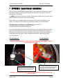
APPENDIX 2 - Speed Sensor Installation .....................................................................................................43
7.1
Speed Sensor Alignment......................................................................................... 44
8
APPENDIX 3 – Display Mounting Template (to scale).......................................................................... 45
9
APPENDIX 4 - ETB Fuel Sender Fitting Instructions ............................................................................... 46
9.1
Fitting the sender to the fuel tank............................................................................ 46
9.2
Fuel Sender Adjustment.......................................................................................... 46
10
Appendix 5 – Lap Trigger Alignment ............................................................................................................ 47
11
APPENDIX 6 – Specification .............................................................................................................................. 48
11.1.1
Power Supply ...................................................................................................48
11.1.2
Environmental ..................................................................................................48
11.1.3
Physical ...........................................................................................................48
11.1.4
Cleaning/Care...................................................................................................48
11.1.5
Warranty ..........................................................................................................48
Version: 1.01
Page 3