1
© ETB Instruments LTD 2008
DigiDash2 - LITE Manual
2 DD2 - LITE Installation
2.1 Mounting the LITE Dipslay
Before cutting any holes in the dashboard, make sure that the location of the LITE Display is easily
visible from the driver’s final position. Also ensure that there is sufficient clearance behind the unit
for the connectors and loom.
Note : The display should be directed towards the driver. If the dash is mounted at too steep an angle
the shift lights and warning lights will not be easily visible.
The LITE has been designed to mount on a flat dash panel behind the steering wheel and this is the
recommended position.
Templates for the fixing screw holes on the Display unit are shown in Appendix 3.
2.2 Sensor Installation
2.2.1 Speed Sensor
The LITE is supplied with a solid state speed sensor and this must be used to provide the speed
signal for the DigiDash2. The sensor consists of a hall-effect magnetic pickup housed in an M12
Nylon threaded rod.
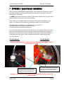
Two magnets are provided for attachment to either a propshaft, wheel hub or drive-shaft coupling.
The magnets should be fixed in position using either ‘Chemical Metal’ or a suitable Epoxy Resin
Adhesive, (For example ‘Araldite’). If possible, a 6mm diameter recess (1mm deep) can be drilled
to help locate the magnets. If you have the choice it is recommended to install the speed sensor on
the propshaft as accuracy will be improved.
The magnets have small ‘dots’ on one face. These denote the magnet’s North pole. The magnet
MUST be mounted with the dot facing down. For further help in setting up the speed sensor and
magnets, please refer to Appendix 2 (Section 6).
You will need to fabricate a suitable metal bracket to hold the sensor in a position such that the
magnets pass in front of the sensor as they rotate in relation to the vehicle’s speed. Using the
threaded body and nuts supplied, the sensor should be adjusted until the gap between the sensor
and magnets is approximately 1mm
The sensor must be mounted so that this gap remains constant. This means that the sensor must
be mounted such that it moves in unison with the surface upon which the magnets are mounted.
Examples of this would be:Magnets location
Differential / Propshaft Flange
Propshaft – Gearbox output
Front wheel hub
Sensor Bracket Location
Differential Casing
Gearbox
Steering arm
(Please see Quick Start Guide or Appendix 2, Section 6 for further visual reference.)
Version: 1.06
Page 7