1
DPS-575
Digital Processing
Synchronizer
Installation and Operation Manual
707-575
Edition C
Trademarks and Copyright
ADAC, ADCOE, BO/S, Command Control System (CCS), DigiBus,
DigiPeek, Digital Glue, DPS, DigiWorks, DTV Glue, Engineering The
Big Picture, EventWORKS, EZ HD, Focused on the Future, Genesis,
HDTV Glue, HEDCO, Innovision, ISIS, JUNO, LeFont, Leitch, Leitch
Network Systems, LNS, LogoMAX, LogoMotion, Media File, MediaPort,
MIX BOX, Monarch, Motion File, NEO, OPUS, PanelMAPPER, Pilot,
Portal, PROM-Slide, RouterWORKS, StillFile, Still Net, Tekniche,
Unilock, VIA, ViewGuard, Xplus, and Leitch XPRESS are trademarks or
registered trademarks of Leitch Technology Corporation in the United
States, Canada, and/or other countries.
All other trademarks are the property of their respective owners.
Copyright 2002, Leitch Technology Corporation. All rights reserved.
Printed in Canada.
DPS-575
Digital Processing
Synchronizer
Installation and Operation Manual
Edition C
November 2002
Preface
Purpose
This manual details the features, installation procedures, operational
procedures, and specifications of the DPS-575 Installation and
Operation Manual.
Audience
This manual is written for technicians and operators responsible for
installation, setup, and/or operation of DPS-575 Installation and
Operation Manual.
Writing Conventions
To enhance your understanding, the authors of this manual have
adhered to the following text conventions:
Bold
Indicates dialog box, property sheet, field, button, checkbox,
listbox, combo box, menu, submenu, window, list, and
selection names.
Italics
Indicates email addresses, names of books and publications,
and first instances of new terms and specialized words that
need emphasis.
CAPS
Indicates a specific key on the keyboard, such as ENTER,
TAB, CTRL, ALT, DELETE.
Code
Indicates variables or command-line entries, i.e., a DOS entry,
something you type into a field, etc.
>
Indicates direction of navigation through a hierarchy of
menus and windows.
hyperlink
Indicates a jump to another location in the document or
elsewhere (such as a website).
DPS-575 Installation and Operation Manual
iii
Preface
Revision History
iv
Edition Date
Revision History
A
October 2000
Initial release.
B
January 2001
Formatting changes.
C
November 2002 Formatting changes.
DPS-575 Installation and Operation Manual
Preface
Important Safety Instructions
Review the following safety precautions to avoid injury and prevent
damage to this product or any products connected to it. Read these
instructions. Keep these instructions. Heed all warnings. Follow all
instructions.
Servicing
Only qualified personnel should perform service procedures. Refer all
servicing to qualified service personnel. Servicing is required when the
apparatus has been damaged in any way, such as power-supply cord or
plug is damaged, liquid has been spilled or objects have fallen into the
apparatus, the apparatus has been exposed to rain or moisture, does not
operate normally, or has been dropped.
Safety Terms and Symbols
Terms and Symbols in This Manual
WARNING:
Statements identifying conditions or practices that can result in
personal injury or loss of life: High voltage is present. Uninsulated
dangerous voltage within the product’s enclosure may be sufficient
to constitute a risk of electric shock to persons.
CAUTION:
Statements identifying conditions or practices that can result in
damage to the equipment or other property: Important operating
and maintenance (servicing) instructions in the literature
accompanying the product.
Terms and Symbols on the Product
DANGER:
High voltage and indicates a personal injury hazard immediately
accessible as one reads the marking.
WARNING:
Indicates a personal injury hazard not immediately accessible as
one reads the marking.
CAUTION:
Indicates a hazard to property including the product or to take
attention and refer to the manual.
DPS-575 Installation and Operation Manual
v
Preface
Protective ground (earth) terminal.
Fuse:
Replace with same type and rating of fuse.
Observe precautions for handling electrostatic-sensitive devices.
Injury Precautions
WARNING!
To reduce the risk of electric shock, do not expose this apparatus to
rain or moisture.
CAUTION
RISK OF ELECTRIC SHOCK
DO NOT OPEN
WARNING!
Potentially lethal voltages are present within this product’s frame
during normal operation. The AC power cord must be
disconnected from the frame before the top panel is removed. (In
frames with multiple power supplies, remove ALL power cords.)
Power should not be applied to the frame while the top is open,
unless properly trained personnel are servicing the unit.
[PL Poland] Przod zdjeciem pokrywy wyciagnac wtyczke z gniazda
sieciowego.
[French] AVIS: RISQUE DE CHOC ELECTRIQUE - NE PAS
OUVRIR. INSTALLER SUR SUPPORT DE MONTAGE
SEULEMENT.
vi
DPS-575 Installation and Operation Manual
Preface
AVIS - Risque de choc electrique. Ne pas
ouvrir.
DPS-575 Installation and Operation Manual
vii
Preface
Use Proper Power Cord
To avoid fire hazard, use only the power cord specified for this
product.
Ground the Product
Do not defeat the safety purpose of the polarized or grounding-type
plug. A polarized plug has two blades with one wider than the other.
A grounding type plug has two blades and a third grounding prong.
The wide blade or the third prong are provided for your safety.
When the provided plug does not fit into your outlet, consult an
electrician for replacement of the obsolete outlet.
[United Kingdom] WARNING: THIS APPLIANCE MUST BE
EARTHED.
[Sweden] APPARATEN SKALL ANSLUTAS TILL JORDAT
UTTAG NÄR DEN ANSLUTS TILL ETT NÄTVERK.
Do Not Operate Without Covers
To avoid electrical shock or fire hazard, do not operate this product
with covers or panels removed.
Use Proper Fuse
To avoid fire hazard, use only the fuse type and rating specified for
this product.
Do Not Operate in Wet/Damp Conditions
To reduce the risk of fire or electric shock, do not expose this
apparatus to rain or moisture.
Do Not Operate in an Explosive Atmosphere
To avoid injury or fire hazard, do not operate this product in an
explosive atmosphere.
Avoid Exposed Circuitry
To avoid injury, remove jewelry such as rings, watches, and other
metallic objects. Do not touch exposed connections and
components when power is present.
viii
DPS-575 Installation and Operation Manual
Preface
Product Damage Precautions
Use Proper Power Source
Do not operate this product from a power source that supplies
more than the specified voltage.
Use Proper Voltage Setting
Before applying power, ensure that the line selector is in the proper
position for the power source being used.
Provide Proper Ventilation
To prevent product overheating, provide proper ventilation.
Do Not Block Any Ventilation Openings
Do not block any of the ventilation openings. Install in accordance
with the manufacturer’s instructions.
Only Use Attachments/Accessories Specified by the Manufacturer
Do Not Operate With Suspected Failures
Refer all servicing to qualified service personnel. Servicing is
required when the apparatus has been damaged in any way, such as
power-supply cord or plug is damaged, liquid has been spilled or
objects have fallen into the apparatus, the apparatus has been
exposed to rain or moisture, does not operate normally, or has been
dropped.
For Products with Multiple Power Cords:
CAUTION: This unit can have more than one power supply cord.
To de-energize the internal circuitry, disconnect all power cords
before servicing.
[Norwegian] ADVARSEL: Utstyret kan ha mere ennn en
tilførselsledning. For å gjore interne deler spennigsløse må alle
tilførselsledningene trekkes ut.
[Sweden] VARNING: Denna apparat har mer än en nätanslutning.
Samtliga nätkablar måste bortkopplas för att göra de interna
kretsarna spänningsfria.
DPS-575 Installation and Operation Manual
ix
Preface
Do Not Use This Apparatus Near Water
Do not expose this apparatus to dripping or splashing water.
Ensure that no objects filled with liquid, such as vases or cups, are
placed on the apparatus.
Clean Only With a Dry Cloth
Keep Product Away from Heat Sources
Do not install near any heat sources such as radiators, heat registers,
stoves, or other apparatus (including amplifiers) that produce heat.
Install Near Socket Outlet
The equipment shall be installed near the socket outlet, and a
disconnect device shall be easily accessible.
Protect the Power Cord
Protect the power cord from being walked on or pinched
particularly at plugs, convenience receptacles, and the point where
they exit from the apparatus.
Attention:
Observe precautions for handling electrostatic-sensitive devices.
See “Preventing Electrostatic Discharge” below for details.
Fuse Replacement:
CAUTION: FOR CONTINUED PROTECTION AGAINST RISK
OF FIRE, REPLACE ONLY WITH THE SAME TYPE OF FUSE.
[French]ATTENTION: REMPLACER UNIQUEMENT PAR UN
FUSIBLE DE MEME TYPE.
x
List of replaceable fuses
Marking
F1 main primary (P.S.)
F4A/250 V
DPS-575 Installation and Operation Manual
Preface
Preventing Electrostatic Discharge
CAUTION: Electrostatic discharge (ESD) can damage components
in the product. To prevent ESD, observe these precautions when
directed to do so:
Use a Ground Strap. Wear a grounded antistatic wrist strap to
discharge the static voltage from your body while installing or
removing sensitive components.
DPS-575 Installation and Operation Manual
•
Use a Safe Work Area. Do not use any devices capable of
generating or holding a static charge in the work area
where you install or remove sensitive components. Avoid
handling sensitive components in areas that have a floor or
benchtop surface capable of generating a static charge.
•
Handle Components Carefully. Do not slide sensitive
components over any surface. Do not touch exposed
connector pins. Handle sensitive components as little as
possible.
•
Transport and Store Carefully. Transport and store
sensitive components in a static-protected bag or
container.
xi
Preface
Certifications and Compliances
This product has been tested and found to comply with the following
CE, FCC, UL, ICES and CSA standards.
EMC Standards
Standard
Description
EN 55103-1:1997 Emissions, Conducted and Radiated, per EN 55022 Class
A; Peak Inrush Current - Product Family Standard Audio, Video, Audio-Visual and Entertainment Lighting
Control Apparatus for Professional Use.
Peak Inrush Current is 21.7A max
EN 55103-2:1997 Immunity, Electromagnetic environment E4 -controlled
EMC Environment - Product Family Standard - Audio,
Video, Audio-Visual and Entertainment Lighting
Control Apparatus for Professional Use.
xii
EN 61000-4-2
Electrostatic Discharge
4kV contact discharge (direct & indirect)
8kV air discharge
EN 61000-4-3
Radiated RF Immunity
3 V rms/m, 80-1000 MHz, 1 kHz 80% AM Modulation
EN 61000-4-4
Electrical Fast Transient
± 1 kV on AC Lines
± 0.5 kV on I/O Lines
EN 61000-4-5
Surge Withstand Immunity
±1 kV Common Mode on AC Lines
± 0.5 kV Differential Mode on I/O Lines
EN 61000-4-6
Conducted RF Immunity
3 V rms/m, 0.15-80 MHz, 150Ω, 1 kHz 80%
AM Modulation on AC & I/O Lines
EN 61000-4-8
Magnetic Field Immunity 50 Hz, 3 A/m
EN 61000-4-11
Dipp100% - 20 ms Dip 60% - 100 ms
Dropouts >95% for 5 sec, 5 times at 10 sec interval
EN 61000-3-2
Harmonic Current Emissions Class A (Other)
EN 61000-3-3
Voltage Fluctuation and Flicker in Low-Voltage Supply
Systems
DPS-575 Installation and Operation Manual
Preface
Per the provision of the Electromagnetic Compatibility Directive 89/
336/EEC of 3 May 1989 as amended by 92/31EEC of 28 April 1992 and
93/68/EEC, Article 5 of 22 July 1993.
These devices are for professional use only and comply with Part 15 of
FCC rules. Operation is subject to the following two conditions:
1. These devices may cause interference to Radio and TV receivers in
residential areas.
2. These devices will accept any interference received, including
interference that may cause undesired operations.
This Class A digital apparatus meets all requirements of the
Canadian Interference-Causing Equipment Regulations.
Changes or modifications not expressly approved by Leitch, the part
responsible for compliance to the FCC Part 15 Rule, could void the
user’s authority to operate this equipment legally in the US.
Safety Standards
Standard
Description
EN 60950
Safety of information technology equipment, including
electrical business equipment (IEC 60950 (1999)), per
the provision of the Low-Voltage Directive 73/23/EEC
of February 19, 1973 as amended by 93/68/EEC.
CSA C22.2 No. 1
Safety standard for Audio/Video and similar electronic
equipment.
UL 1419
Safety requirements for professional audio video
equipment.
DPS-575 Installation and Operation Manual
xiii
Preface
xiv
DPS-575 Installation and Operation Manual
Contents
Chapter 1: Introducing the DPS-575 .............................1
Overview ..................................................................................................... 1
Chapter 2: Installation and Configuration ...................5
Installation ..................................................................................................5
Unpacking and Inspection ..................................................................5
Mounting ............................................................................................. 6
Hardware Options ...............................................................................6
Firmware Options ...............................................................................6
Configuration ............................................................................................. 7
Breakout Cable .................................................................................... 7
Video Connections ............................................................................. 9
Audio Connections ........................................................................... 11
Remote Control Ports ....................................................................... 13
Chapter 3: Operation–Front Panel Controls ..............17
Functional Areas of the Panel ................................................................... 17
VFD Display Panel ................................................................................... 19
Resetting the Unit .............................................................................. 20
Menu Controls .......................................................................................... 21
Navigating Through the Menus ........................................................ 21
Changing Parameters ........................................................................ 21
Remote Control ................................................................................. 22
Status Indicators (LEDs) .......................................................................... 23
Genlock .............................................................................................. 23
EDH ................................................................................................... 23
TBC .................................................................................................... 24
Autotrack ........................................................................................... 24
DPS-575 Installation and Operation Manual
xv
Contents
DigiDuplex ........................................................................................ 24
Option ............................................................................................... 25
Video Input Selection ............................................................................... 26
Audio Input Selection .............................................................................. 27
Freeze Controls ......................................................................................... 29
Mode Selection ......................................................................................... 30
Bypass ................................................................................................ 30
TSG .................................................................................................... 30
Keyer .................................................................................................. 30
N/R .................................................................................................... 31
Proc Amp Controls and User Keys .......................................................... 32
Automatic Proc Amp Setup (“Gimme Bars”) .................................. 32
Luma .................................................................................................. 32
Black .................................................................................................. 32
Chroma .............................................................................................. 33
Hue .................................................................................................... 33
Memory ............................................................................................. 34
User 1 and User 2 .............................................................................. 34
Option ............................................................................................... 35
DV Control Mode .................................................................................... 36
User-Programmable Buttons ................................................................... 37
Power-Up Buttons .................................................................................... 38
Force Firmware Download ............................................................... 38
Self-Test Mode .................................................................................. 38
Erase Firmware .................................................................................. 39
Factory Reset ..................................................................................... 39
Chapter 4: Feature Cross-Reference .......................... 41
Overview ................................................................................................... 41
Features ..................................................................................................... 42
Animated Logo Insertion .................................................................. 42
Audio Configuration ......................................................................... 42
Audio Delay ....................................................................................... 42
Audio-Follows-Video ....................................................................... 43
Audio Input Selection ....................................................................... 43
Audio Test Tone Generator .............................................................. 43
Automatic Proc Amp Setup Mode (“Gimme Bars”) ....................... 43
Bandwidth Limiting .......................................................................... 44
xvi
DPS-575 Installation and Operation Manual
Contents
Bypass Mode ..................................................................................... 44
Comb Filtering .................................................................................. 44
DigiDuplex Mode .............................................................................. 45
DV Device Control (Option) ............................................................ 45
Framestore/Linear Keyer .................................................................. 46
Genlock Timing ................................................................................. 46
GPI Control ....................................................................................... 46
Hot Switch/Trouble Slide .................................................................. 47
Key Channel Output ......................................................................... 47
Noise Reduction (Option) ................................................................ 47
NTSC/PAL Configurations ............................................................... 48
Proc Amp .......................................................................................... 48
Remote Control ................................................................................. 48
Test Signal Generator ........................................................................ 48
Time Base Corrector ......................................................................... 49
Upgrading the Firmware ................................................................... 49
Vertical Blanking ............................................................................... 49
Video Configuration ......................................................................... 50
Video Freeze Mode ........................................................................... 50
Video Input Selection ....................................................................... 50
Video Strobe Mode ........................................................................... 51
VITS Insertion ................................................................................... 51
Voice-Over Mixing ........................................................................... 51
Chapter 5: Video Setup Menu .....................................53
Overview ................................................................................................... 53
Configuration Options ............................................................................. 54
Luma Gain ......................................................................................... 54
Black Level ......................................................................................... 54
Chroma Gain ..................................................................................... 54
Hue Phase .......................................................................................... 55
Color Balance – Cb ............................................................................ 55
Color Balance – Cr ............................................................................ 55
Video AGC ........................................................................................ 55
AGC Bias ........................................................................................... 56
Input H-Position ............................................................................... 56
Input Y/C Delay ................................................................................ 56
Sync Mode ......................................................................................... 57
DPS-575 Installation and Operation Manual
xvii
Contents
3D Comb Decoder ............................................................................ 58
3D Chroma Motion Bias ................................................................... 59
Comb Filter Decoder ........................................................................ 59
DigiDuplex Mode .............................................................................. 60
Self Setup to Bars ............................................................................... 61
More Video Settings ................................................................................. 62
Hot Switch ......................................................................................... 62
Hot Switch Delay .............................................................................. 63
Trouble Slide ..................................................................................... 63
Trouble File ....................................................................................... 64
Freeze Mode ...................................................................................... 65
Field Select ......................................................................................... 66
Strobe Rate ........................................................................................ 66
Input Source ...................................................................................... 66
Test Signal Out .................................................................................. 67
TSG .................................................................................................... 68
Output Burst ...................................................................................... 69
SDI Clip ............................................................................................. 69
Composite Clip ................................................................................. 70
EDH Detection .................................................................................. 70
EDH Error Count .............................................................................. 71
Clamp Speed ...................................................................................... 71
Aux Output ....................................................................................... 72
Aux Sync/Comp ................................................................................ 72
Aux Sync Level .................................................................................. 73
CAV-Y Composite ............................................................................ 73
Analog Width .................................................................................... 73
Chroma Pairing Filter ....................................................................... 74
Chapter 6: Menus and Features................................... 75
Overview ................................................................................................... 75
Menu Controls .......................................................................................... 76
Video Setup .............................................................................................. 77
More Video Settings .......................................................................... 78
Audio Setup ................................................................................................ 79
Channel 1 ........................................................................................... 79
Channel 2 ........................................................................................... 80
Both Channels ................................................................................... 81
xviii
DPS-575 Installation and Operation Manual
Contents
Global Audio Config ......................................................................... 83
Audio Limiter (Optional) ................................................................. 85
Keyer Setup ............................................................................................... 86
Change Settings ................................................................................. 86
Noise Reduction (Option) ....................................................................... 87
DV Control [option] ................................................................................ 88
Timing Setup ............................................................................................ 89
TSG/Image Grabbing ............................................................................... 90
System Config ........................................................................................... 91
Misc Setup ......................................................................................... 91
One Time Video Setup ...................................................................... 92
Remote Control Setup ....................................................................... 92
Flash Memory Mgmt ......................................................................... 93
Chapter 7: Audio Setup Menu ......................................95
Overview ................................................................................................... 95
Channel 1 and/or Channel 2 .................................................................... 96
Analog Bypass ................................................................................... 97
AES/EBU .......................................................................................... 97
Gain-R ............................................................................................... 98
Gain-L ................................................................................................ 98
DDPlex Gain-R ................................................................................. 99
DDPlex Gain-L .................................................................................. 99
Fixed Delay ...................................................................................... 100
In Op. Level-R ................................................................................. 100
In Op. Level-L ................................................................................. 101
Headroom-R ................................................................................... 101
Headroom-L .................................................................................... 102
Out Op. Level-R .............................................................................. 103
Out Op. Level-L ............................................................................... 103
Tone Level ....................................................................................... 103
Test Freq-L ...................................................................................... 104
Test Freq-R ...................................................................................... 104
Balanced .......................................................................................... 104
Termination .................................................................................... 105
Stereo Mode .................................................................................... 105
Phase Invert L .................................................................................. 106
SDI In ............................................................................................... 106
DPS-575 Installation and Operation Manual
xix
Contents
Aud Follows Vid .............................................................................. 107
AFV Format Options ...................................................................... 108
Global Audio Config. ............................................................................. 109
Auto Track ...................................................................................... 109
Master Mute .................................................................................... 109
Audio Bypass ................................................................................... 110
AES Data Grade ............................................................................... 110
AES Elec. Levels ............................................................................... 111
AES Source ...................................................................................... 111
96 kHz AES Output ......................................................................... 112
DigiDuplex Input ............................................................................ 113
DDPlex AES/EBU Out .................................................................... 113
SDI Out ............................................................................................ 114
Channel In->Out ............................................................................ 114
Sample Rate ..................................................................................... 115
SDI Embedding ............................................................................... 115
SDI L/R De-Embed ......................................................................... 116
Pitch Change ................................................................................... 116
Mute In Freeze ................................................................................. 117
Dolby-E (Data) Mode ..................................................................... 117
Voice-Over Pgm. Level ................................................................... 118
Voice-Over Fade ............................................................................. 118
Voice-Over ...................................................................................... 119
Bit Width ......................................................................................... 120
Audio Limiter (Optional) ....................................................................... 121
Soft Limit ......................................................................................... 121
Range ............................................................................................... 122
Attack .............................................................................................. 122
Decay ............................................................................................... 123
Chapter 8: Keyer Setup Menu .................................... 125
Overview ................................................................................................. 125
Fade Out .................................................................................................. 126
Cut Out ................................................................................................... 127
Fade In .................................................................................................... 128
File ........................................................................................................... 129
Settings .................................................................................................... 130
Change Settings ...................................................................................... 131
xx
DPS-575 Installation and Operation Manual
Contents
Shift X .............................................................................................. 131
Shift Y .............................................................................................. 131
Fade In Time ................................................................................... 132
Max Opacity .................................................................................... 132
Fade Out Time ................................................................................. 132
Repeat Count ................................................................................... 133
Frame Rate ....................................................................................... 133
Loop Mode ...................................................................................... 134
Bumper Style ................................................................................... 134
Save These Settings .......................................................................... 135
Chapter 9: Noise Reduction Menu (Option) ........... 137
Overview ................................................................................................. 137
Noise Reduction ..................................................................................... 138
Split Screen .............................................................................................. 139
Spatial Filter ............................................................................................ 140
Spatial Filter Mix ..................................................................................... 141
Horizontal Bandwidth ............................................................................ 142
Vertical Bandwidth-Y ............................................................................. 143
Vertical Bandwidth-C ............................................................................. 144
Temporal NR-Luma ............................................................................... 145
Temporal NR-Chroma ........................................................................... 146
Chapter 10: DV Control Menu (Option) ................... 147
Overview ................................................................................................. 147
DV Control ............................................................................................. 148
Chapter 11: Timing Setup Menu ............................... 149
Overview ................................................................................................. 149
Genlock ................................................................................................... 150
Sub Carrier Phase ................................................................................... 150
Horizontal ............................................................................................... 151
Line Advance .......................................................................................... 151
Vertical .................................................................................................... 151
DPS-575 Installation and Operation Manual
xxi
Contents
Chapter 12: System Config Menu.............................. 153
Overview ................................................................................................. 153
Line Standard (525/625) ......................................................................... 154
Current ............................................................................................ 154
Switch to 525 ................................................................................... 154
Switch to 625 ................................................................................... 154
Disable Autoswitch / Switch to Auto .............................................. 154
Version Information .............................................................................. 155
Warm Reset ............................................................................................ 156
Reset to Factory Defaults ........................................................................ 157
Enable Extra Options .............................................................................. 158
Factory Calibration ................................................................................. 159
Misc Setup ............................................................................................... 160
Internal Temp ................................................................................. 160
Video Delay ..................................................................................... 160
Keylock ............................................................................................ 160
Function Bypass .............................................................................. 161
GPI-1 Function ............................................................................... 162
GPI-2 Function ............................................................................... 163
GPO Function ................................................................................. 164
Genlock Changes ............................................................................ 165
VFD Brightness ............................................................................... 165
LED Brightness ................................................................................ 165
Idle Timeout .................................................................................... 166
Idle Cycle Time ............................................................................... 166
Key Reload on Reset ........................................................................ 167
System Password ............................................................................ 167
Web Password ................................................................................. 168
One Time Video Setup ........................................................................... 169
Source ID ......................................................................................... 169
Setup Level (in) ............................................................................... 169
Setup VBI (in) ................................................................................. 169
Setup Level (out) ............................................................................. 170
VITS/Blanking Fld1 ........................................................................ 171
VITS/Blanking Fld2 ........................................................................ 172
VBI Setup Levels ............................................................................. 173
Remote Control Setup ............................................................................ 174
Baud Rate ........................................................................................ 174
xxii
DPS-575 Installation and Operation Manual
Contents
Remote Control ............................................................................... 174
RS-422 Termination ........................................................................ 174
IP Address ....................................................................................... 175
Netmask ........................................................................................... 175
Gateway ........................................................................................... 176
Machine Name ................................................................................ 177
DCN Address .................................................................................. 177
Remote Watch ................................................................................. 178
Ethernet Address ............................................................................. 178
Flash Memory Mgmt .............................................................................. 179
List Files ........................................................................................... 179
Memory Usage ................................................................................ 179
Backup All Settings .......................................................................... 180
Restore All Settings ......................................................................... 180
Chapter 13: TSG/Image Grabbing ............................ 181
Overview ................................................................................................. 181
Grab 10-bit Video ................................................................................... 182
Grab 8-bit Video ..................................................................................... 183
Grab Linear Key ...................................................................................... 184
Grab & Apply Luma Key ........................................................................ 185
Luma Key Gain ....................................................................................... 186
Threshold ................................................................................................ 187
Appendix A: Specifications........................................ 189
Video Specifications ............................................................................... 189
Inputs ............................................................................................... 189
Outputs ............................................................................................ 190
Signal Processing ............................................................................. 190
Frequency Response ....................................................................... 190
Signal to Noise ................................................................................. 191
Processor Controls .......................................................................... 191
Remote Control ............................................................................... 192
Audio Specifications ............................................................................... 193
Analog Inputs ................................................................................. 193
AES / EBU Inputs ............................................................................ 193
SDI Embedded Inputs ..................................................................... 194
Analog Inputs ................................................................................. 194
DPS-575 Installation and Operation Manual
xxiii
Contents
AES/EBU Outputs ........................................................................... 194
SDI Embedded Outputs .................................................................. 195
Miscellaneous Specifications .......................................................... 195
General Specifications ............................................................................ 196
Appendix B: Test Signals ............................................ 197
DPS-575 (NTSC mode) .......................................................................... 197
DPS-575 (PAL mode) ............................................................................. 199
Appendix C: Installation of Hardware Options ....... 201
Overview ................................................................................................. 201
Precautions ............................................................................................. 202
Starting the Installation .......................................................................... 203
Installation of DVM-5010 I/O Option Board (DVM-5010) ................. 204
Installation of Audio Synchronizer
Module (AS-575) .................................................................................... 206
Removal of Audio Synchronizer
Module (AS-575) .................................................................................... 209
Installation of Animated Logo
Option Board (AL-575) ......................................................................... 210
Completing the Installation .................................................................... 212
Appendix D: The Uploader Software........................213
Overview ................................................................................................. 213
Software Installation ............................................................................... 214
Starting the Software ............................................................................... 215
Using the Software .......................................................................... 215
Upgrading Firmware .............................................................................. 217
Uploading Files ....................................................................................... 218
Converting Files ...................................................................................... 219
Field Ordering in Stills and Animations ................................................ 222
Maximum Animation Sequence
Length and Frame Size ........................................................................... 224
Appendix E: DigiDuplex Mode .................................. 225
What is DigiDuplex? ....................................................................... 225
Controlling the DigiDuplex Signal Path ................................................ 226
Video ............................................................................................... 226
Audio ............................................................................................... 227
Configuration Example .......................................................................... 229
xxiv
DPS-575 Installation and Operation Manual
Contents
Appendix F: Ethernet Control ................................... 231
Configuring Ethernet Control ................................................................ 231
Web Browser Control ............................................................................. 232
Device Control ................................................................................ 232
Confidence Monitoring .................................................................. 234
Flash File System ............................................................................. 234
Upload File to Unit .......................................................................... 235
Upgrading Firmware ....................................................................... 235
Other Machines on this Network ................................................... 236
Warm Reset ..................................................................................... 236
CCS-DPS-575 Gateway Options ............................................................ 237
Overview .......................................................................................... 237
CCS-DPS-575 Gateway Features .................................................... 238
CCS Pilot Features ........................................................................... 239
Appendix G: Cable Pinouts........................................ 241
Video Cable ............................................................................................. 241
Audio Cable (Standard) ......................................................................... 242
Audio Cable (Optional) .......................................................................... 243
DPS-575 Installation and Operation Manual
xxv
Contents
xxvi
DPS-575 Installation and Operation Manual
Chapter 1
Introducing the DPS-575
Overview
The Leitch DPS-575™ Digital Processing Synchronizer is equally suited
for analog, digital, or hybrid facilities, and represents the ideal choice for
broadcasters making the transition to digital television (DTV). Available
in video-only and audio/video configurations, these synchronizers
provide an ideal bridge from analog video signals, such as satellite and
microwave feeds, to digital production facilities. The DPS-575 is an
auto-sensing dual-standard (PAL/NTSC) device.
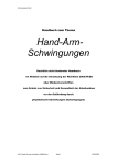
Figure 1-1. The Leitch DPS-575
The DPS-575 offers unparalleled I/O flexibility. Four input and five
output formats are provided on all units:
•
Serial Component Digital Video (SDI) input and output
•
Component Analog Video (Betacam®) input and output
•
S-Video (S-VHS / Hi8) input and output
•
Composite Video input and output
•
RGB-S output
DPS-575 Installation and Operation Manual
1
Chapter 1: Introducing the DPS-575
Overview
DV (IEEE-1394) I/O with transport control is available as an option. A
built-in auto-sense TBC circuit provides seamless mode switching
between direct color and heterodyne sources such as camcorders and
VTRs.
The versatile DPS 12-bit comb filter offers three processing modes:
Simple, Adaptive-2D, and Adaptive-3D.
3D combing utilizes a proprietary algorithm to combine information
from previous frames to eliminate residual subcarrier artifacts, such as
cross luminance and cross chrominance. 3D combing can also be
applied to non-composite sources, to clean up component video that
was previously decoded from a composite source using lower-quality
combing in other equipment. Combining the high-quality comb filter
with proprietary advanced 12-bit analog encoding provides maximum
signal transparency and optimum transcoding.
The DPS-575 also features optional adjustable temporal and spatial
digital noise reduction and variable 2D filtering with separate horizontal
and vertical bandwidth controls. Applying digital bandwidth filtering
and noise reduction prior to MPEG encoding can improve overall
MPEG performance through entropy reduction.
The exclusive DigiDuplex Mode provides bi-directional connectivity
between analog tape machines and digital audio/video routing systems.
DigiDuplex saves space and money by enabling digital to analog
transcoding with simultaneous analog to digital frame synchronization–
all in one compact box. In DigiDuplex Mode, the unit's SDI video input is
routed directly to the analog video outputs, which feed the inputs of an
analog device. The analog output of the device can be simultaneously
connected to the synchronizer's analog inputs, where it is processed and
sent to the SDI video outputs. Conversion between digital and analog
audio is handled in a similar fashion.
With the addition of the four-channel audio synchronizer module, the
DPS-575 can provide dual stereo audio and video synchronization in a
single rack-unit-high package. The internal audio synchronizer option
supports analog, AES/EBU digital, and embedded SDI and DV audio
I/O (with the DV I/O module installed). All audio outputs are
simultaneously active, which enables both analog and digital audio
devices to be connected at the same time. All four audio channels can
dynamically track the internal delay of the video synchronizer, and a
fixed delay can also be specified, ensuring proper lip sync regardless of
the program source. Audio test tones can be generated at
operator-specified frequencies.
2
DPS-575 Installation and Operation Manual
Overview
Chapter 1: Introducing the DPS-575
The DPS-575 is more than just a synchronizer. In addition to the features
listed above, other functions include:
•
Time Base Corrector
•
Audio Synchronizer
•
Digital Framestore with Linear Keyer
•
Digital Noise Reduction (optional)
•
DV Transcoder (optional)
•
Video AGC
•
10-bit Video Test Signal Generator with Zone Plate
•
Audio Test Signal Generator
•
VITS Inserter, Video Bandwidth Processor
•
Serial Digital Audio Embedder/De-Embedder
•
Animated Logo Inserter (optional)
These functions can be accessed from the front panel or from an
RC-575™ remote control.
DPS-575 Installation and Operation Manual
3
Chapter 1: Introducing the DPS-575
4
Overview
DPS-575 Installation and Operation Manual
Chapter 2
Installation and Configuration
Installation
Unpacking and Inspection
The DPS-575 unit has been thoroughly calibrated and inspected, both
electronically and mechanically, to ensure that it meets the published
specifications.
The following items are included with each unit:
Quantity
Description
1
DPS-575 Digital Processing Synchronizer
1
AC Power Cord (Part # 773-254 or 773-505)
1
Rear Support Bracket (Part # 741-983)
1
Video Breakout Cable (Part # 774-753)
1
Audio Breakout Cable (Part # 774-755) (included only with
the DPS-575AV)
2
12 x Analog Audio Terminal Blocks (Part # 722-184)
(included only with the DPS-575AV, which may be
preinstalled on your unit)
DPS-575 Installation and Operation Manual
5
Chapter 2: Installation and Configuration
Installation
Mounting
The DPS-575 fits into most standard consoles or 19-inch racks. If the
unit is to be mounted into a rack, then the included rear support bracket
must be used. Care must be taken to select a dry, well-ventilated location
with a minimum of dust and vibration. Also, leave sufficient clearance
from the unit’s sides to allow for proper air circulation.
After unpacking the unit and before installing into a console or rack,
allow at least 30 minutes for temperatures to equalize and to eliminate
any condensation that may have developed.
Hardware Options
If you purchased hardware options, such as the Audio Synchronizer
module, the Animated Logo option, or the DV I/O module, separately
from the main unit, you will need to install them. See Appendix C
“Starting the Installation” on page 203 for detailed instructions for
installing your options safely and correctly.
Firmware Options
If you purchased firmware options such as the Noise Reduction with
Video Bandwidth Filtering and Audio Limiter options, they must be
enabled by using the Enable Extra Options setting in the System Config
menu. See Chapter 12 “System Config Menu” on page 153 for more
information.
6
DPS-575 Installation and Operation Manual
Configuration
Chapter 2: Installation and Configuration
Configuration
Breakout Cable
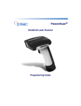
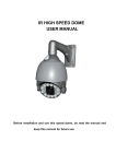
Figure 2-1 and Figure 2-2 display the left and the right hand side of the
DPS-575AV back panel.
Figure 2-1. DPS-575AV Back Panel - Left Hand Side
Figure 2-2. DPS-575AV Back Panel - Right Hand Side
Some connections to the DPS-575 are provided on the supplied
breakout cables. These breakout cables must be connected to the
specified ports on the back of the unit.
Multi I/O Breakout Cable
The RGB output from the 15-pin
Multi I/O breakout cable does not
operate in the DigiDuplex Mode;
it only operates in the Normal
mode.
The Multi I/O breakout cable (Part # 774-753) connects to the DB-15F
high-density connector labeled Multi I/O on the right rear side of the
unit. This cable provides connections for RGB output, sync/key/
auxiliary-composite output, S-Video output, and GPI.
DPS-575 Installation and Operation Manual
7
Chapter 2: Installation and Configuration
Configuration
AES/EBU Audio Breakout Cable
The AES/EBU audio breakout
cable is available on
audio-equipped units only.
8
The AES/EBU audio breakout cable connects to the DB-25F connector
labeled AES/EBU on the rear of the unit. This cable provides connections
for AES/EBU audio input and output. The standard AES/EBU audio
breakout cable (Part # 774-755) provides BNC connections; an optional
audio breakout cable (Part # 774-470A) provides BNC and XLR
connections.
DPS-575 Installation and Operation Manual
Configuration
Chapter 2: Installation and Configuration
Video Connections
The following are the video connections on the rear of the DPS-575, in
left-to-right order, followed by those on the supplied breakout cable.
DV Input/Output
This six-pin IEEE-1394 connector, labeled DV I/O, is used to connect DV
(often referred to as “Firewire”) devices. In addition to carrying DV
video and audio input and output, this port also provides DV device
control, allowing control of the DV device directly from the DPS-575.
This connection is active only if the optional DV I/O module is installed.
S-Video Input
The four-pin connector on the rear of the unit, labeled S-Video, is used
for S-Video (Y/C) signals, such as from an S-VHS or Hi8 device. It is
normally connected to the S-Video output of a playback VTR using a
standard four-pin to four-pin S-Video cable. Some JVC “industrial” type
S-VHS players use a seven-pin connector for their S-Video output. To
interface with such machines, a seven-pin to four-pin adapter cable is
required from the manufacturer of the VTR.
Component Analog Video Input
These three BNC connectors, labeled CAV-Y In, R-Y In, and B-Y In, are
used to input the signals from analog component devices, such as
Betacam VTRs.
If component analog video input is not needed, the CAV-Y In
connection can be reassigned as a second composite video input with
the CAV-Y Composite option in the Video Setup menu (see Chapter 5
“Video Setup Menu” on page 53).
Composite Video Input
This BNC connector, labeled Composite In, is used to feed composite
1Vp-p 75Ω video to the DPS-575. In Synchronizer mode, the input
video signal must be direct color or monochrome (such as from a
satellite feed or live camera); in Timebase Corrector or Auto Switching
mode, the input signal can be connected to the video output of a
heterodyne source such as a camcorder or VTR.
DPS-575 Installation and Operation Manual
9
Chapter 2: Installation and Configuration
Configuration
Serial Digital Input
This BNC connector, labeled SDI In, accepts serial digital ITU-R BT.601
video and embedded audio data at a rate of 270 Megabits per second.
Serial Digital Reclocked Output
This BNC connector, labeled SDI Reclocked, provides a digitally
regenerated copy of the SDI Input, with no processing applied.
Serial Digital Outputs
These BNC connectors, labeled SDI 1 Out and SDI 2 Out, provide the
processed and synchronized serial digital ITU-R-BT.601 video and
embedded audio, at an output rate of 270 Megabits per second.
Composite Video Output
These BNC connectors, labeled Comp 1 Out and Comp 2 Out, provide
processed, synchronized/timebase-corrected versions of any of the input
signals. If the unit is set to Bypass mode, the Composite Input is
bypassed directly to the Comp 1 output (the leftmost of the two
connectors), providing an unprocessed signal. Comp 2 Out operates as
normal (providing processed output from the selected video input). The
Comp 1 input is automatically bypassed to the Comp 1 Out output when
the unit is off.
Genlock Reference
These BNC connectors, labeled Genlock In and Genlock Loop, are used to
loop a genlock signal through the unit to establish the timing for its
video output signal. The signal for this input must always be stable, such
as the output from a black-burst or color-bar generator. Do not attempt
to use a signal that has not been timebase-corrected. When a valid signal
is connected to the Genlock In input, the video output of the DPS-575
will be genlocked to this signal, and the Genlock LED will be on. When
no external reference is supplied to the Genlock input, the unit will
operate using its own internal sync generator. If the Genlock Loop is
unused, terminate it with a 75Ω terminator.
S-Video Output
This four-pin connector on the Multi I/O breakout cable provides
processed, synchronized/timebase-corrected S-Video (Y/C) output.
10
DPS-575 Installation and Operation Manual
Configuration
Chapter 2: Installation and Configuration
RGB(S) Video Output
These four BNC connectors on the Multi I/O breakout cable, comprising
auxiliary Red, Green, Blue, and Sync, provide processed, synchronized/
timebase-corrected RGB(S) (RGB with auxiliary sync) video output. If
RGB without auxiliary sync is sufficient, the Aux Sync connection can be
reassigned as an auxiliary composite output. If RGB(S) output is not
required, these outputs can be reconfigured to provide a key channel
output.
Auxiliary Composite Output
The Aux Sync connection on the Multi I/O breakout cable, normally
used for sync in RGB(S) (RGB with auxiliary sync)video output, can be
reassigned to provide an auxiliary composite video output with the Aux
Sync/Comp option in the Video Setup menu.
Key Output
The Aux Sync connection on the Multi I/O breakout cable, normally
used for sync in RGB(S) (RGB with auxiliary sync) video output, can be
reassigned to provide a key channel output with the Aux Output option
in the Video Setup menu.
Audio Connections
The DPS-575AV can process two stereo pairs of analog, AES/EBU, Serial
Digital (SDI) or DV audio (with the optional DV I/O module). The
audio inputs can be selected from the front panel or Audio Setup menu,
and the operator can specify which of the stereo channels are to be
processed. All of the outputs are active simultaneously.
Analog Audio Inputs and Outputs
Two stereo pairs of analog audio inputs and outputs are supported,
designated Channel 1 and Channel 2 on the rear of the unit. Each is
comprised of a left and right component. Each analog audio input
channel can be configured as 600Ω or high impedance. Each channel
can be configured as balanced or unbalanced.
DPS-575 Installation and Operation Manual
11
Chapter 2: Installation and Configuration
Configuration
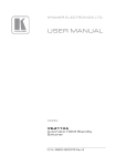
Two terminal strips (one for Channel 1, one for Channel 2) provide
analog audio connections. Each terminal strip uses the following
pinouts:
In
Out
+ - G+ - G+ - G+ - G
Left Right Left Right
Figure 2-3. Terminal Strips
AES/EBU Inputs
Two BNC connectors (one for each of Channel 1 and 2) are provided on
the standard audio breakout cable (Part # 774-755) for AES/EBU input.
An optional audio breakout cable (Part # 774-470A) provides four
connectors for AES/EBU input: two XLR (one for each of Channel 1 and
2), and two BNC (one for each of Channel 1 and 2). The XLR connectors
are used for AES/EBU balanced audio input, while the BNC connectors
are used for unbalanced AES/EBU input. Note that only two of the above
input connections can be used at a time (one for Channel 1 and one for
Channel 2), and they must be of the same type (XLR or BNC). The AES
Source menu option selects between the XLR and BNC connections.
AES/EBU Outputs
Two BNC connectors (one for each of Channel 1 and 2) are provided on
the standard audio breakout cable for AES/EBU output.
An optional audio breakout cable, provides four connectors for
AES/EBU output: two XLR (one for each of Channel 1 and 2), and two
BNC (one for each of Channel 1 and 2). The XLR connectors are used
for AES/EBU balanced audio output, while the BNC connectors are used
for unbalanced AES/EBU output. Both BNC and XLR outputs are
available concurrently.
Audio Delay Pulse/GPI Output
The general-purpose GPI output, a BNC connection on the Multi I/O
breakout cable, can be configured for use as an audio delay pulse output,
to be sent to an external audio delay box or synchronizer.
12
DPS-575 Installation and Operation Manual
Configuration
Chapter 2: Installation and Configuration
Serial Digital Embedded Audio Input (SDI)
The unit accepts four channels of embedded audio on the SDI input
port. The four channels can be selected from any group on the SDI
input.
Serial Digital Embedded Audio Output (SDI)
Any of the selected audio inputs can be embedded into the output of the
SDI stream. The operator can select which group of 4 audio channels (of
the 16 available in the SDI format) the output will be embedded into.
Remote Control Ports
In addition to GPI input (for remote triggering of functions such as
Freeze) and output (for triggering external devices), all functions of the
DPS-575 can be remotely controlled by devices capable of either RS-232
or RS-422.
Two additional remote control methods are supported:
•
Digital Coaxial Network (DCN), for use with controllers such as the
RC-575 Remote Control Systems.
•
10BaseT Ethernet networking, for control through a TCP/IP-based
network.
The type of control, and any appropriate parameters, are selected in the
System Config menu, under the Remote Control submenu (see Chapter 12
“System Config Menu” on page 153).
RS-232 and RS-422
This DB-9F connector, labeled RS-232/422 on the rear panel of the unit,
is used to upgrade the internal FLASH firmware. The RS-232 port is also
used for transferring files to the unit from a Microsoft® Windows® based
workstation via custom software (included). See Appendix D, “The
Uploader Software” on page 213 for information on transferring files
from a Microsoft Windows system.
DPS-575 Installation and Operation Manual
13
Chapter 2: Installation and Configuration
Configuration
Ethernet Port
The 10BaseT Ethernet connector, labeled Ethernet on the rear of the
unit, is used to connect the DPS-575 to a TCP/IP-based network for
remote control and status monitoring. Control of the unit is then
handled through web-browsing software or an RC-575 remote control
panel. See Appendix F, “Ethernet Control” on page 231 for details of
controlling the unit from your web browser. Ethernet can also be used to
control additional DPS-575 units from the front panel of this unit. When
using Ethernet, the IP Address, Netmask, and Gateway settings of the
unit must be configured for your network; your network administrator
can provide you with these settings. These settings are located in the
System Config menu, under the Remote Control submenu. See Chapter 12
“System Config Menu” on page 153 for more information.
DCN
The BNC connector, labeled DCN on the rear of the unit, is used to
provide a DCN (Digital Coaxial Network) interface for remote control
and status monitoring. DCN is a proprietary network in which 75Ω coax
is used as a multi-drop, bi-directional network. Using a BNC
T-connector on the DPS-575, loop coax between each unit and the
remote controller (such as the RC-575). At each end of the chain, install
a 75Ω terminator. Every DPS-575 is assigned a unique DCN address at
the factory, so there is no software configuration required. The
maximum cable length (total) in a DCN configuration should be limited
to 2,000 feet (0.6 km). DCN can also be used to control additional
DPS-575 units from the front panel of this unit.
RC-575 Remote Control
The RC-575 remote control provides an Ethernet port, which permits it
to be conveniently connected to a TCP/IP network. See the RC-575
manual for instructions on using the DPS RC-575 remote control.
GPI Inputs
Two RCA-jack GPI inputs are provided on the Multi I/O breakout cable.
These allow a GPI-based external controller to trigger functions of the
unit. The function triggered by each GPI input is configured in the
System Config menu, under the Misc Setup submenu. See Chapter 12
“System Config Menu” on page 153 for more information.
14
DPS-575 Installation and Operation Manual
Configuration
Chapter 2: Installation and Configuration
GPI Output
A user-configurable general-purpose BNC output is provided on the
Multi I/O breakout cable. This output can be used for feeding an audio
delay pulse to an external audio synchronizer, or it can be configured as
a GPI output to trigger external devices. The functionality of this output
is configured with the GPO Output option in the System Config menu (see
Chapter 12 “System Config Menu” on page 153 for more information).
DPS-575 Installation and Operation Manual
15
Chapter 2: Installation and Configuration
16
Configuration
DPS-575 Installation and Operation Manual
Chapter 3
Operation–Front Panel Controls
Functional Areas of the Panel
3
Enter
Default
Genlock
Comp
EDH
S-Video
COARSE/FINE
JOG/SHUTTLE
JOG/SHUTTL
TBC
CAV
Exit
Remote
Autotrack
SDI
DigiDuplex
DV
Option
Option
1
2
Video In
1 Analog 2
Frz Mode
Bypass
TSG
Luma
Take
Keyer
N/R
Memory
Black Chroma
Hue
AES
SDI
DV
Audio In
Option
User 1
User 2
Option
Reset
reset
AFV
4
5
6
7
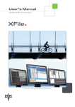
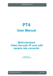
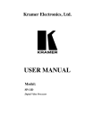
Figure 3-1. The Leitch DPS-575 Front Panel (Right Side)
The front panel controls of the DPS-575 are organized into seven main
functional areas:
1. Menu controls
2. Status indicators
3. Video input selection
4. Audio input selection
5. Freeze controls
6. Mode selection
7. Proc Amp controls and User buttons
DPS-575 Installation and Operation Manual
17
Chapter 3: Operation–Front Panel Controls
Functional Areas of the Panel
In addition, while in DV Control mode (selected from the Main menu),
the Control knob and specific buttons become dedicated to device
control of a DV deck or camcorder. See “DV Control Mode”on page 36.
Certain buttons on the front panel can be user-programmed to specific
functions (see “User-Programmable Buttons” on page 37), and some
buttons activate special functions when they are held down during
power-up of the unit (see “Power-Up Buttons” on page 38).
18
DPS-575 Installation and Operation Manual
VFD Display Panel
Chapter 3: Operation–Front Panel Controls
VFD Display Panel
Menu options, selections, and feedback are shown on the Vacuum
Fluorescent Display (VFD) panel. When the unit is first powered-up, the
display shows product information, which is then replaced by the idle
screen:
Figure 3-2. Idle Screen Display
The idle screen is a real-time status screen which provides feedback
about various parameters of the currently selected inputs. The idle
screen is shown when the user is not adjusting parameters or browsing
the menus.
At regular intervals, the display
“inverts” itself. In the initial state,
text and information appears lit,
over an “unlit” background. In the
inverted state, the background will
be lit, with the text and information
appearing “unlit” (black). This
periodic inversion is normal; it does
not indicate any kind of problem or
status. The inversion is done to
preserve the life span of the display
panel.(Leaving the display in a
single state can cause display pixels
to burn out prematurely.)
The first three lines of the idle screen provide real-time feedback of the
Luma, Black, and Chroma levels of the currently selected video input
source.
With the Audio Synchronizer module installed, the next two lines of the
display show real-time feedback of the Channel 1 and 2 audio input
levels.
On units with the DV I/O module installed, the bottom line of the idle
screen displays the current DV Time Code reported by the connected
DV device, and just to the left of this, the current DV transport state.
The Machine Name specified in the System Config menu (see “System
Config Menu” on page 153) is also shown on the idle screen. On units
without DV or audio capability, the idle screen will display the current
measured video delay through the unit.
DPS-575 Installation and Operation Manual
19
Chapter 3: Operation–Front Panel Controls
VFD Display Panel
Resetting the Unit
In the video input selection section of the front panel, just to the right of
the CAV and SDI indicators, is a small hole. This hole provides access to
the Reset button, which resets the DPS-575 unit. This is equivalent to
power-cycling the unit.
20
DPS-575 Installation and Operation Manual
Menu Controls
Chapter 3: Operation–Front Panel Controls
Menu Controls
All options and parameters for the DPS-575 are accessed through
configuration menus, which appear on the display panel. Selecting any
of the menu and submenu options follows the same procedure as using
them. See “Features” on page 42.
Navigating Through the Menus
To navigate through the menus, follow these steps:
1. With the idle screen displayed, press the Enter button. (If the idle
screen is not displayed, press Exit repeatedly until it is.) The display
panel will show the Main menu options.
2. Scroll through the list using the Control knob until the desired
submenu is highlighted. Press the Enter button to enter the submenu.
3. Use the Control knob and Enter button to choose and activate the
option you want. If there are further submenus, use the procedure in
step 2 to select between them, and to select the option you wish to
change.
4. Press the Exit button while in a menu or submenu to return to the
previous submenu, or if you are at the Main menu, to return to the
idle screen.
Changing Parameters
Once you have selected the option you wish to change, use the Control
knob to set the new value for the parameter. When setting parameters
that have discrete value options (such as selecting Field, Frame, or Strobe
mode), the Control knob will cycle through the valid settings.
Adjustments affect the output
immediately as the knob turns.
For parameters that have a numerical range of values, the display shows
both a numeric and a visual representation of the range. Use the Control
knob to set the new value.
When setting parameters that have a numerical range of values, you can
use the Control knob to switch between Fine and Coarse adjustment
mode. When you first enter the parameter adjustment screen, the
Control knob is in Fine mode. Press the Enter button to switch to Coarse
adjustment mode; the Enter button lights up. Coarse adjustment mode
allows you to make large adjustments more quickly. Press Enter again to
return the Control knob to Fine mode.
DPS-575 Installation and Operation Manual
21
Chapter 3: Operation–Front Panel Controls
Menu Controls
For example, when setting a parameter, you may use the Control knob to
adjust the value in increments of 0.02 in Fine mode and 0.50 in Coarse
mode.
Press the Default button to reset the configuration parameter to its
default values. The Default LED lights up whenever the current value of
the parameter is equivalent to the default value, whether you reached this
value by pressing the Default button, or by scrolling to it with the Control
knob.
Press the Exit button to accept your new value and return to the previous
menu or submenu.
Remote Control
By placing the DPS-575 in Remote mode, you can control additional
DPS-575 units on the same DCN or Ethernet network from the front
panel of this unit.
Press the Remote front-panel button to bring up a list of available units
that can be controlled. The <local device> option, representing the unit
being used, is always available on this list. Use the Control knob to scroll
through the list of available devices. Highlight the unit you wish to
control, and then press the Enter button to activate it. Select <local
device> to exit Remote mode and resume normal single-unit operation.
Once you have selected a remote unit to control, all front-panel features
operate as if you were actually at the front panel of that remote unit. The
VFD display, status indicators, and buttons (LEDs) all reflect the status
of the remote unit. All buttons and controls, with the exception of the
Remote button, control the remote unit, not the one you are physically
operating. To stop controlling the remote unit, use the Remote button to
select a new unit (or the local device) to control.
The light on the Remote button flashes while the unit is remotely
controlling a device.
22
DPS-575 Installation and Operation Manual
Status Indicators (LEDs)
Chapter 3: Operation–Front Panel Controls
Status Indicators (LEDs)
The status indicator LEDs provide visual feedback on the current mode
and operating conditions of the unit.
Genlock
The Genlock LED indicates the current status of the external genlock
source.
LED Status
Operating Condition
On
If the unit is configured to Auto Genlock mode, this
indicator will be lit as long as a stable genlock source is
connected to the unit.
Off
If no genlock source is present, the unit will automatically
switch to Internal Genlock mode, and this indicator will
flash.
Flash
If the unit is configured to Internal Genlock mode, it will
operate on its own internal crystal, and this indicator will
be unlit.
EDH
The EDH LED indicates the current configuration and status of Error
Detection Handling (EDH) in the input Serial Digital video stream.
LED Status
Operating Condition
Off
If the indicator is off or unlit, EDH detection is turned
off in the unit.
Flash
If the indicator flashes briefly, EDH detection is enabled,
and EDH errors have been detected and not yet cleared by
the operator. The actual count of these errors is reported in
the EDH Error Count menu option.
DPS-575 Installation and Operation Manual
23
Chapter 3: Operation–Front Panel Controls
Status Indicators (LEDs)
TBC
The TBC LED indicates whether or not the composite input signal is
timebase-corrected by the unit’s TBC circuitry.
LED Status
Operating Condition
On
If the unit is in Sync mode, the internal TBC is not active,
and this indicator will be off.
Off
If the unit is in TBC mode, the unit will timebase-correct
the input signal (generally for heterodyned signals from
sources such as a VTR), and this indicator will be lit.
Flash
If the unit is in Auto-Switch mode, the unit will sense the
incoming composite video signal and select between Sync
and TBC modes automatically; in this mode, the indicator
will flash when the TBC is active.
Autotrack
The Autotrack LED indicates whether or not the audio Auto Track mode
is enabled.
LED Status
Operating Condition
On
When enabled, this indicator will be lit, and the unit will
automatically delay the audio data to match the delay of the
video data through the Synchronizer (up to four fields).
Off
The indicator will be off when Auto Track is disabled.
DigiDuplex
The DigiDuplex LED indicates whether or not the unit is in DigiDuplex
Mode.
24
LED Status
Operating Condition
On
In DigiDuplex mode, the indicator is lit, and the unit’s SDI
video input is routed to the analog video outputs, while the
selected analog video input is simultaneously synchronized
and sent to the SDI output. With an audio-equipped unit,
conversion between digital and analog audio is handled in
similar fashion, simultaneously with the video.
Off
This indicator is unlit when DigiDuplex Mode is off.
DPS-575 Installation and Operation Manual
Status Indicators (LEDs)
Chapter 3: Operation–Front Panel Controls
See Appendix E, “DigiDuplex Mode” on page 229 for a detailed
explanation of DigiDuplex Mode and its settings.
Option
The Option LED indicates the status and/or configuration of the
currently installed option card module (if any). The meaning of this
indicator varies depending on the particular option installed; please see
the documentation for your option module for further details.
DPS-575 Installation and Operation Manual
25
Chapter 3: Operation–Front Panel Controls
Video Input Selection
Video Input Selection
To select the current (active) video input, press the Video In button until
the desired LED becomes lit. The selectable inputs are:
•
Comp (Composite)
•
S-Video
•
CAV (Component Analog Video)
•
SDI (Serial Digital)
•
DV– With the optional DV module installed, DV can also be selected
as an input.
•
Option–If an option card module is installed that includes an
additional video input, it will be selectable as Option.
If no input signal is present on the selected video input, the
corresponding LED will flash.
26
DPS-575 Installation and Operation Manual
Audio Input Selection
Chapter 3: Operation–Front Panel Controls
Audio Input Selection
On DPS-575AV units and DPS-575 units with the Audio Synchronizer
module installed, to select the current (active) audio input:
•
Press the Audio In button to open a menu where you can select the
Channel 1 audio input; this is the same as the Ch1-Input menu
option.
•
Press the Audio In button a second time to open a menu where you
can select the Channel 2 audio input; this is the same as the Ch2-Input
menu option.
The selectable audio inputs, with corresponding LEDs, are:
•
Analog
•
AES/EBU
•
SDI Embedded
•
DV–With the optional DV module installed, DV can also be selected
as an input.
•
Option–If an option card module is installed that includes an
additional audio input, it will also be selectable.
•
If AFV (Audio FollowsVideo) mode is enabled through the audio
menus (see Chapter 7, “Audio Setup Menu” on page 95), the AFV
indicator for that channel will be lit. In this mode, each of the
selectable video inputs has an audio input selection linked to it.
Whenever the video input selection is changed, the audio input
selection for any AFV-enabled channel automatically changes
correspondingly.
You can override AFV mode by manually selecting a different audio
input even when AFV is enabled. This does not, however, turn AFV
mode off; the next time the video input selection is changed, the
audio will again follow it. AFV mode can only be disabled through
the audio menus.
The AFV link to each of the video inputs is set through the Audio
Setup menu. See Chapter 7, “Audio Setup Menu” on page 95.
The input selection for Channels 1 and 2 cannot be selected
independently if 96 kHz AES Output mode is enabled; they must
always be set to the same input source. See Chapter 7, “Audio Setup
Menu” on page 95.
DPS-575 Installation and Operation Manual
27
Chapter 3: Operation–Front Panel Controls
Audio Input Selection
The selection menus also provide access to two “special” audio modes:
•
Mute–disables audio output; while in this mode, all input source
LEDs for that channel will be on.
•
Test Tones–outputs audio test tones from the unit. The parameters of
the test tones (Level, Frequency) are set from the Audio Setup menu
(see Chapter 7, “Audio Setup Menu” on page 95). While in Test Tones
mode, all input source indicator LEDs for that channel will flash.
When Dolby-E (Data) Mode is enabled (see Chapter 7, “Audio Setup
Menu” on page 95), the audio input selection for Channel 1 is locked to
AES/EBU, and only this Channel supports Dolby-E Data. SDI
Embedded Audio cannot be used in this mode.
Press and hold the Audio In button for one second to open the Audio
Setup menu (the same as is available through the Main menu), from
which you can set additional audio configuration options.
When one input channel is routed to both output channels through the
Channel In->Out or Aud Follows Vid menu options (see Chapter 7,
“Audio Setup Menu” on page 95 for details), only that input channel’s
LED is lit to indicate the audio input source.
On DPS-575 units without audio capability, the Audio In button is userprogrammable; that is, you can assign the button to a desired menu
function. See “User-Programmable Buttons” on page 37 for instructions
on assigning this button to a menu function.
28
DPS-575 Installation and Operation Manual
Freeze Controls
Chapter 3: Operation–Front Panel Controls
Freeze Controls
The freeze controls provide instant access to freezing individual frames
or fields of the incoming video source, strobing the incoming video, or
performing a 3:2 pull-down on the input source.
Press the Frz Mode button to open a menu where you can select a Freeze
mode to apply to the incoming video. This is the same as the Freeze
mode menu option under the Video Setup menu.
Press the Frz Mode button multiple times to cycle through the different
modes, or the Control knob can be used for selection. The available
modes are:
•
Frame–freezes an entire frame of the incoming video
•
Field–freezes a single field of the incoming video
•
Strobe–strobes the incoming video
•
Film–applies a 3:2 pull-down to the incoming video, effectively
giving a simulated 24fps look to the video output
Press the Take button to activate the selected Freeze mode and apply it to
the incoming video. The LED on the Take button flashes while Freeze
mode is active. Press Take again to return to the live video feed.
If Field Freeze mode is selected, the display panel indicates which field of
the video is frozen (1, 2, 3, or 4). This will initially be the same as the
value of the Field Select menu option. The Control knob changes the
currently selected field (and the Field Select menu option is updated
accordingly).
If Strobe Freeze mode is selected, the display panel indicates the current
strobe rate (number of frames per update) applied to the incoming video
(1 to 255). This will initially be the same as the value of the Strobe Rate
menu option. The Control knob changes the rate (and the Strobe Rate
menu option is updated accordingly).
Press the Frz Mode button while Frame or Field Freeze mode is already
active to toggle between Frame and Field Freeze mode.
The Mute In Freeze audio menu option specifies whether or not audio
output will be muted while the video is frozen in Frame or Field mode.
DPS-575 Installation and Operation Manual
29
Chapter 3: Operation–Front Panel Controls
Mode Selection
Mode Selection
The mode selection controls provide direct access to Bypass, Test Signal
Generator (TSG), and Noise Reduction (NR) functions.
Bypass
The Bypass button toggles between Process and Bypass mode. The
Bypass button must be held in for one second to activate Bypass mode; a
normal press will return to Process mode. Process mode is the normal
mode of operation. In Bypass mode, no processing is applied to the
Composite In video signal; it is passed directly to Composite Out.
Similarly, in Bypass mode, no processing is applied to the analog and
AES/EBU audio inputs; they are routed directly to the outputs.
The light on the Bypass button flashes while the unit is in Bypass mode.
Composite In and the analog and AES/EBU audio inputs are also
bypassed when the power to the unit is off.
TSG
The TSG button sets the unit to Test Signal Generator mode. Press the TSG
button to activate the Test Signal Generator and send the currently
selected test pattern to all video outputs. This will initially be the test
pattern selected in the TSG menu option of the Video Setup menu.
When TSG mode is active, the light on the TSG button flashes, and the
display panel shows a list of available test patterns (and indicates which
one is active).
You can change the displayed pattern by scrolling through the list with
the Control knob and pressing the Enter button to select a new pattern.
Press the TSG button again to return the outputs to the incoming video
feed.
Keyer
The Keyer button provides access to the unit’s linear keyer. Press the
Keyer button once to take you directly to the Keyer Setup menu, from
which you can enable the keyer and configure the keyer settings.
30
DPS-575 Installation and Operation Manual
Mode Selection
Chapter 3: Operation–Front Panel Controls
If a file (animation or still) to be displayed has been selected previously,
press the Keyer button a second time to fade in the animation or still over
the live video. Press the Keyer button a third time to fade it back out.
Note that if it is an animation being keyed, the animation will fade out
automatically after the number of repetitions specified in the Repeat
option of the keyer settings, if not faded out manually first.
If no file has been previously selected, press the Keyer button a second
time to take you to the keyer’s file selection list (equivalent to the File
option of the Keyer Setup menu), from which you can select a file from
among the still images and animations stored in the unit. These images
could have been uploaded to the unit from a PC (see Appendix D, “The
Uploader Software” on page 213, and Appendix F, “Ethernet Control” on
page 231) or grabbed from video from the TSG/Image Grabbing menu.
The image or animation to be displayed or keyed is selected by scrolling
through the list with the Control knob and then pressing the Enter button
to select the desired file. The file is loaded, and you are returned to the
Keyer Setup menu. Press the Keyer button again to fade in the file, and
press it again to fade it out.
The light on the Keyer button flashes while the key is in transition
(fading in or fading out) and lights up while the key is displayed. See
Chapter 8, “Keyer Setup Menu” on page 125 for more information about
the Keyer Setup menu.
N/R
On units with the Noise Reduction and Video Bandwidth Filtering option
installed, press the N/R button to access the noise reduction functions of
the unit. Press the N/R button once to take you directly to the Noise
Reduction menu, from which you can configure noise reduction settings.
See Chapter 9, “Noise Reduction Menu (Option)” on page 137 for a
detailed description of the Noise Reduction menu.
Press the N/R button repeatedly to toggle the noise reduction features on
and off. The light on the N/R button lights up when noise reduction is
enabled.
DPS-575 Installation and Operation Manual
31
Chapter 3: Operation–Front Panel Controls
Proc Amp Controls and User Keys
Proc Amp Controls and User Keys
The Proc Amp controls allow the modification, storing, and recalling of
Proc Amp settings.
Automatic Proc Amp Setup (“Gimme Bars”)
The Luminance Gain, Black Level, Chrominance Gain, and Hue can all
be automatically set by the unit based on incoming SMPTE bars.
To use the Gimme Bars automatic setup mode, SMPTE bars (or other
75% bars) must be supplied to the currently selected video input. Press
and hold the Luma button; the four Proc Amp parameters are
automatically adjusted.
Luma
Press the Luma button to adjust the luminance gain by using the Control
knob and menu controls (see “Menu Controls” on page 21). This is
equivalent to the Luma Gain menu option in the Video Setup menu.
While setting the luminance gain, the display panel also shows the
maximum luminance level (in IRE or mV) of the incoming video signal.
Valid Range
-99.99 dB to 6.00 dB (Y/C, SDI, DV)
-8.01 dB to 4.04 dB (Composite, CAV)
Default Setting
0.00 dB
Black
Press the Black button to adjust the black level by using the Control knob
and menu controls (see “Menu Controls” on page 21). This is equivalent
to the Black Level menu option in the Video Setup menu.
While setting the black level, the display panel also shows the minimum
luma level of the incoming video signal.
32
Valid Range
-30.0 IRE to 30.0IRE (525-line mode)
-210.0 mV to 210.0 mV (625-line mode)
Default Setting
0.0 IRE (525-line mode)
0.0 mV(625-line mode)
DPS-575 Installation and Operation Manual
Proc Amp Controls and User Keys
Chapter 3: Operation–Front Panel Controls
Chroma
Press the Chroma button to adjust the chrominance gain by using the
Control knob and menu controls (see “Menu Controls” on page 21). This
is equivalent to the Chroma Gain menu option in the Video Setup menu.
While setting the chrominance gain, the display panel also shows the
saturation peak (in%) of the incoming video signal.
Valid Range
-99.99dB to 6.00 dB (Y/C, SDI, DV, Composite)
-8.01 dB to 4.07 dB (CAV)
Default Setting
0.00 dB
Hue
Press the Hue button to adjust the output phase by using the Control
knob and menu controls (see “Menu Controls” on page 21). This is
equivalent to the Hue Phase menu option in the Video Setup menu. This
button can be reprogrammed if not needed. See “User-Programmable
Buttons” on page 37 for instructions on assigning a different function to
this button.
Valid Range
-45.010° to 44.080°
Default Setting
0.000°
DPS-575 Installation and Operation Manual
33
Chapter 3: Operation–Front Panel Controls
Proc Amp Controls and User Keys
Memory
Press the Memory button to provide access to the Proc Amp memory
controls. These controls allow you to store and recall Proc Amp settings
profiles. Up to 10 settings profiles can be stored, containing the settings
for Luma Gain, Black Level, Chroma Gain, and Hue.
Storing Settings
To store the current Proc Amp settings:
1. Press the Memory button.
2. Use the Control knob to select Store, and press the Memory button.
3. Use the Control knob to select one of the 10 available memory
locations, and then press Memory.
Recalling Settings
To recall the stored Proc Amp settings:
1. Press the Memory button.
2. Use the Control knob to select Recall, and then press the Memory
button.
3. Use the Control knob to select the desired profile from one of the 10
available memory locations, and then press Memory again.
The Proc Amp settings are changed to those stored in the specified
profile. In addition to the 10 memory locations, you can select the
Unity Values profile, which resets the Proc Amp settings to factory
preset unity.
User 1 and User 2
The User 1 and User 2 buttons are programmable and have no default
function. See “User-Programmable Buttons” on page 37 for instructions
on assigning desired functions to these buttons.
34
DPS-575 Installation and Operation Manual
Proc Amp Controls and User Keys
Chapter 3: Operation–Front Panel Controls
Option
On units in which an option module has been added, the Option button
may be used to control functions of that hardware option. Please see the
documentation for your option module for further details. If the option
board does not require the Option button to be used, it becomes
user-programmable and has no default function. See “UserProgrammable Buttons” on page 37 for instructions on assigning a
different function to this button.
DPS-575 Installation and Operation Manual
35
Chapter 3: Operation–Front Panel Controls
DV Control Mode
DV Control Mode
On units with the DV I/O option installed, where a DV device (such as a
deck or camcorder) is connected to the DPS-575 by IEEE-1394
(Firewire), you can control transport from the front panel of the unit.
To enable DV device control, select DV Control from the Main menu. (To
reach the Main menu, press the Enter button while the idle screen is
displayed.) The display changes to show the current time code of the DV
device, as well as the transport status (play, stop, etc.). While in DV
mode, the normal functionality of the front panel controls is replaced by
DV device control.
If you look carefully at the front panel of the unit, you will see standard
representations of transport controls below many of the buttons. The
buttons used for DV device control are as follows:
Button
Function
Luma
Stop
Black
Rewind/Scrub Backward
Chroma
Play
Hue
Fast-Forward/Scrub Forward
Memory
Record (used in conjunction with Play)
Option
Pause
Default
Toggle the Control knob between Jog mode and Shuttle
mode
The Control knob functions as a jog or shuttle controller, depending on
the currently selected mode.
To exit DV Control mode and return to normal operation, press the Exit
button.
36
DPS-575 Installation and Operation Manual
User-Programmable Buttons
Chapter 3: Operation–Front Panel Controls
User-Programmable Buttons
You can program many of the front-panel buttons on the DPS-575; they
are user-programmable. That is, you can program them to take the user
to a menu or specific function of your choice.
On all units, the User 1, User 2, and Hue buttons are user-programmable.
On units that do not have audio capability, the Audio In button is also
programmable. On units in which an added option board does not
require the Option button to be used, it can be programmed as well.
Of these buttons, only the Hue button has a default function. If you press
one of the other buttons before it is programmed, the following message
appears on the display panel:
This button has not yet been assigned a
function. To program it, select the desired menu
or setting that you wish to assign to it, using
the normal menu controls. Then press and hold
this button for five seconds.
It is easy to reprogram a button, whether a programmable button already
has a function assigned to it or not. Hold down a programmable button
for five seconds to assign to it whatever menu or option is currently
displayed on the display panel.
For example, to assign the User 1 button to adjust the video AGC Bias,
select the AGC Bias option from the Video Setup menu. With the AGC
Bias adjustment screen displayed, press and hold the User 1 button for
approximately five seconds. All LEDs on the unit will then flash once to
indicate successful programming. If programming fails for any reason
(for example, if you attempt to program a button to the idle screen), all
LEDs on the unit will flash three times quickly.
If the programming fails, any
function previously assigned to
that button will have been
erased, so the button will have to
be reprogrammed.
Once the button is programmed, press it to jump to the menu or option
assigned to it. Press it again to cycle through the values (if the button is
assigned an option) or select the active menu choice (if the button is
assigned a menu).
In the above example, press the User 1 button to take you to the AGC Bias
adjustment screen. Each additional press of the User 1 button cycles
through the allowed adjustment values.
DPS-575 Installation and Operation Manual
37
Chapter 3: Operation–Front Panel Controls
Power-Up Buttons
Power-Up Buttons
Certain special functions of the DPS-575 are accessed by holding down
specific front-panel buttons while turning on the unit.
Force Firmware Download
To force the unit into Firmware Download mode, hold down the Enter
button while turning on the unit.
Normally, the unit automatically enters Firmware Download mode
whenever the Windows-based Uploader® software attempts to upload a
firmware upgrade file to the unit. See Appendix D, “The Uploader
Software” on page 213. However, if the firmware within the unit
becomes corrupted (possibly during a failed firmware upgrade), the unit
may not start up properly, and thus would be unable to automatically
enter Firmware Download mode. In this case, pressing the Enter button
during power-up allows you to upload new firmware to the unit from the
Uploader software.
Self-Test Mode
To force the unit into Self-Test mode, hold down the Bypass button while
turning on the unit. Self-Test mode allows you to test the front-panel
controls and indicators of the unit. The display panel indicates which
particular controls and indicators are being tested.
When you are testing buttons, each press of a button is reported on the
display panel, with the name of the button. To end the testing of buttons,
turn the Control knob left to right.
When you are testing LEDs, each column of indicators on the buttons
lights consecutively left to right. Each row of LEDs on the buttons then
lights consecutively top to bottom. The columns and rows of the
standalone LEDs follow the same pattern, and the process repeats. Press
any button to end the testing of LEDs.
When you are testing the Control knob, each turn reflects a numeric
value shown on the display panel. Press any button to end the testing of
the Control knob, and begin the testing of buttons again.
To exit Self-Test mode, turn the unit off and than back on, or reset the
unit using the Reset button.
38
DPS-575 Installation and Operation Manual
Power-Up Buttons
Chapter 3: Operation–Front Panel Controls
Erase Firmware
After performing this operation,
replacement FPGA and firmware
files must be uploaded to the unit
before the unit will be
operational again.
To erase all FPGA and firmware files from the unit’s memory, hold down
the Keyer button while turning on the unit. This will have to be done if
you are attempting to upgrade the unit’s FPGAs or firmware, but there is
not enough available memory to upload the new file.
Factory Reset
Holding down the Memory button while turning on the unit will
perform a factory reset by clearing the unit’s non-volatile memory.
Clearing the unit’s non-volatile
memory will reset all
configurations to factory default.
All saved setting presets will be
lost.
DPS-575 Installation and Operation Manual
39
Chapter 3: Operation–Front Panel Controls
40
Power-Up Buttons
DPS-575 Installation and Operation Manual
Chapter 4
Feature Cross-Reference
Overview
This section provides a cross-reference between the key features of the
DPS-575, and the primary menu options and controls associated with
their use. Detailed explanations of these features appear in subsequent
chapters. Menu options are listed in the format Menu/Submenu/Option.
If all options in a menu or submenu are relevant to the feature, only the
menu or submenu is listed.
DPS-575 Installation and Operation Manual
41
Chapter 4: Feature Cross-Reference
Features
Features
Animated Logo Insertion
Topic
Location
Keyer Setup Menu
Chapter 8, “Keyer Setup Menu” on
page 125
Front Panel Controls/Mode
Selection/Keyer
Chapter 3 “Keyer” on page 30
The Uploader Software
Appendix D, “The Uploader
Software” on page 213
System Config/Misc Setup/Key
Reload on Reset
Chapter 12, “System Config Menu”
on page 167
Audio Configuration
Topic
Location
Front Panel Controls/Audio Input
Selection
Chapter 3, “Operation–Front Panel
Controls” on page 27
Audio Setup Menu
Chapter 7, “Audio Setup Menu” on
page 95
Topic
Location
Audio Setup/Global Audio Config/
Auto Track
Chapter 7, “Auto Track” on page 109
Audio Setup/Global Audio Config/
Pitch Change
Chapter 7, “Pitch Change” on
page 116
Audio Setup/Both Channels/Ch1
and Ch2 Fixed Delay
Chapter 7, “Fixed Delay” on page 100
Audio Delay
42
DPS-575 Installation and Operation Manual
Features
Chapter 4: Feature Cross-Reference
Audio-Follows-Video
Topic
Location
Audio Setup/Both Channels/Ch1
and Ch2-Aud Follows Vid
Chapter 7, “Aud Follows Vid” on
page 107
Audio Input Selection
Topic
Location
Front Panel Controls/Audio Input
Selection
Chapter 3, “Audio Input Selection”
on page 27
Audio Setup/Both Channels/Ch1
and Ch2
Chapter 7, “Channel 1 and/or
Channel 2” on page 96
Audio Setup/Both Channels/Ch1
and Ch2/Aud Follows Vid
Chapter 7, “Aud Follows Vid” on
page 107
Audio Test Tone Generator
Topic
Location
Front Panel Controls/Audio Input
Selection
Chapter 3, “Audio Input Selection”
on page 27
Audio Setup/Both Channels/Ch1
and Ch2
Chapter 7, “Channel 1 and/or
Channel 2” on page 96
Audio Setup/Both Channels/Ch1
and Ch2/Tone Level
Chapter 7, “Tone Level” on page 103
Audio Setup/Ch1
Tone/Freq-L and R
Chapter 7, “Test Freq-L” on page 104
Automatic Proc Amp Setup Mode (“Gimme Bars”)
Topic
Location
Front Panel Controls/Proc Amp
Controls
Chapter 3, “Proc Amp Controls and
User Keys” on page 32
Video Setup/Self Setup to Bars
Chapter 5, “Self Setup to Bars” on
page 61
DPS-575 Installation and Operation Manual
43
Chapter 4: Feature Cross-Reference
Features
Bandwidth Limiting
Topic
Location
Noise Reduction/Horizontal
Bandwidth
Chapter 9, “Horizontal Bandwidth”
on page 142
Noise Reduction/Vertical
Bandwidth-Y
Chapter 9, “Vertical Bandwidth-Y”
on page 143
Noise Reduction/Vertical
Bandwidth-C
Chapter 9, “Vertical Bandwidth-C”
on page 144
Topic
Location
Front Panel Controls/Mode
Selection
Chapter 3, “Mode Selection” on
page 30
Bypass Mode
System Config/Misc Setup/Function Chapter 12, “Function Bypass” on
Bypass
page 161
Audio Setup/Both Channels/Ch1
and Ch2/Analog Bypass
Chapter 7, “Analog Bypass” on
page 97
Audio Setup/Both Channels/Ch1
and Ch2/AES/EBU
Chapter 7, “AES/EBU” on page 97
Topic
Location
Video Setup/3D Comb Decoder
Chapter 5, “3D Comb Decoder” on
page 58
Video Setup/Comb Filler Decoder
Chapter 5, “Comb Filter Decoder” on
page 59
Comb Filtering
44
DPS-575 Installation and Operation Manual
Features
Chapter 4: Feature Cross-Reference
DigiDuplex Mode
Topic
Location
Video Setup/DigiDuplex Mode
Chapter 5, “DigiDuplex Mode” on
page 60
Audio Setup/Both Channels/Ch1
and Ch2/DDPlex Gain-R
Chapter 7, “DDPlex Gain-R” on
page 99
Audio Setup/Both Channels/Ch1
and Ch2/DDPlex Gain-L
Chapter 7, “DDPlex Gain-L” on
page 99
Audio Setup/Global Audio Config/
DigiDuplex Input
Chapter 7, “DigiDuplex Input” on
page 113
Audio Setup/Global Audio Config/
DDPlex AES-EBU Out
Chapter 7, “DDPlex AES/EBU Out”
on page 113
DigiDuplex Mode
Appendix E, on page 225
DV Device Control (Option)
Topic
Location
DV Control Menu
Chapter 10, “DV Control Menu
(Option)” on page 147
Front Panel Controls/DV Control
Mode
Chapter 3, “DV Control Mode” on
page 36
DPS-575 Installation and Operation Manual
45
Chapter 4: Feature Cross-Reference
Features
Framestore/Linear Keyer
Topic
Location
Keyer Setup Menu
Chapter 8, “Keyer Setup Menu” on
page 125
Front Panel Controls/Mode
Selection
Chapter 3, “Mode Selection” on
page 30
The Uploader Software
Appendix D, “The Uploader
Software” on page 213
TSG-Image Grabbing Menu
Chapter 13, “TSG/Image Grabbing”
on page 181
System Config/Flash Memory Mgmt Chapter 12, “Flash Memory Mgmt”
Submenu
on page 179
System Config/Misc Setup/Key
Reload on Reset
Chapter 12, “Key Reload on Reset” on
page 167
Topic
Location
Timing Setup Menu
Chapter 11, “Timing Setup Menu” on
page 149
System Config/Misc Setup/Genlock
Changes
Chapter 12, “Genlock Changes” on
page 165
Topic
Location
System Config/Misc Setup/GPI-1
Function
Chapter 12, “GPI-1 Function” on
page 162
System Config/Misc Setup/GPI-2
Function
Chapter 12, “GPI-2 Function” on
page 163
System Config/Misc Setup/GPO
Function
Chapter 12, “GPO Function” on
page 164
Genlock Timing
GPI Control
46
DPS-575 Installation and Operation Manual
Features
Chapter 4: Feature Cross-Reference
Hot Switch/Trouble Slide
Topic
Location
Video Setup/More Video Settings/
Hot Switch
Chapter 5, “Hot Switch” on page 62
Video Setup/More Video Settings/
Hot Switch Delay
Chapter 5, “Hot Switch Delay” on
page 63
Video Setup/More Video Settings/
Trouble Slide
Chapter 5, “Trouble Slide” on page 63
Video Setup/More Video Settings/
Trouble File
Chapter 5, “Trouble File” on page 64
Key Channel Output
Topic
Location
Video Setup/More Video Settings/
Aux Output
Chapter 5, “Aux Output” on page 72
Noise Reduction (Option)
Topic
Location
Front Panel Controls:
Mode Selection
Chapter 3, “Mode Selection” on
page 30
Noise Reduction Menu
Chapter 9, “Noise Reduction Menu
(Option)” on page 137
Video Setup/More Video Settings/
Chroma Pairing Filter
Chapter 5, “Chroma Pairing Filter” on
page 74
Video Setup/3D Comb Decoder
Chapter 5, “3D Comb Decoder” on
page 58
Video Setup/3D Chroma Motion
Bias
Chapter 5, “3D Chroma Motion Bias”
on page 59
Video Setup/Comb Filter Decoder
Chapter 5, “Comb Filter Decoder” on
page 59
DPS-575 Installation and Operation Manual
47
Chapter 4: Feature Cross-Reference
Features
NTSC/PAL Configurations
Topic
Location
System Config/Line Standard
(525/625)
Chapter 12, “Line Standard (525/
625)” on page 154
Topic
Location
Front Panel Controls: Proc Amp
Controls
Chapter 3, “Proc Amp Controls and
User Keys” on page 32
Video Setup Menu
Chapter 5, “Video Setup Menu” on
page 53
Topic
Location
Video Connections
Chapter 2, “Video Connections” on
page 9
System Config/Remote Control
Chapter 12, “Remote Control” on
page 174
Ethernet Control
Appendix F, “Ethernet Control” on
page 231
Proc Amp
Remote Control
Test Signal Generator
48
Topic
Location
Front Panel Control/
Mode Selection
Chapter 3, “Mode Selection” on
page 30
Video Setup/More Video Settings/
Test Signal Out
Chapter 5, “Test Signal Out” on
page 67
DPS-575 Installation and Operation Manual
Features
Chapter 4: Feature Cross-Reference
Topic
Location
Video Setup/More Video Settings/
TSG
Chapter 5, “TSG” on page 68
The Uploader Software
Appendix D, “The Uploader
Software” on page 213
TSG-Image Grabbing/Grab 10-bit
Video
Chapter 13, “Grab 10-bit Video” on
page 182
Time Base Corrector
Topic
Location
Video Setup/Sync Mode
Chapter 5, “Sync Mode” on page 57
Upgrading the Firmware
Topic
Location
The Uploader Software
Appendix D, “The Uploader
Software” on page 213
Ethernet Control
Appendix F, “Ethernet Control” on
page 231
Topic
Location
System Config/One Time Video
Setup/VITS-Blanking FLd 1
Chapter 12, “VITS/Blanking Fld1” on
page 171
System Config/One Time Video
Setup/VITS-Blanking FLd 2
Chapter 12, “VITS/Blanking Fld2” on
page 172
Vertical Blanking
DPS-575 Installation and Operation Manual
49
Chapter 4: Feature Cross-Reference
Features
Video Configuration
Topic
Location
Video Setup Menu
Chapter 5, “Video Setup Menu” on
page 53
Front Panel Controls/Proc Amp
Controls
Chapter 3, “Proc Amp Controls and
User Keys” on page 32
Topic
Location
Video Setup/More Video Settings/
Strobe Rate
Chapter 5, “Strobe Rate” on page 66
Front Panel Controls: Freeze
Controls
Chapter 3, “Freeze Controls” on
page 29
Video Setup/More Video Settings/
Freeze Mode
Chapter 5, “Freeze Mode” on page 65
Video Setup/More Video Settings/
Field Select
Chapter 5, “Field Select” on page 66
Audio Setup/Global Audio Config/
Mute In Freeze
Chapter 7, “Mute In Freeze” on
page 117
Video Freeze Mode
Video Input Selection
50
Topic
Location
Front Panel Controls/Video Input
Selection Menu
Chapter 3, “Video Input Selection” on
page 26
Video Setup/More Video Settings/
Input Source
Chapter 5, “Input Source” on page 66
Video Setup/More Video Settings/
CAV-Y Composite
Chapter 5, “CAV-Y Composite” on
page 73
DPS-575 Installation and Operation Manual
Features
Chapter 4: Feature Cross-Reference
Video Strobe Mode
Topic
Location
Front Panel Controls/Freeze
Controls
Chapter 3, “Freeze Controls” on
page 29
Video Setup/More Video Settings/
Freeze Mode
Chapter 5, “Freeze Mode” on page 65
Video Setup/More Video Settings/
Strobe Rate
Chapter 5, “Strobe Rate” on page 66
Topic
Location
System Config/One Time Video
Setup/VITS-Blanking Fld1
Chapter 12, “VITS/Blanking Fld1” on
page 171
System Config/One Time Video
Setup/VITS-Blanking Fld2
Chapter 12, “VITS/Blanking Fld2” on
page 172
Topic
Location
Audio Setup/Global Audio Config/
Voice-Over Pgm.Level
Chapter 7, “Voice-Over Pgm. Level”
on page 118
Audio Setup/Global Audio Config/
Voice-Over Fade
Chapter 7, “Voice-Over Fade” on
page 118
Audio Setup/Global Audio Config/
Voice-Over
Chapter 7, “Voice-Over” on page 119
VITS Insertion
Voice-Over Mixing
DPS-575 Installation and Operation Manual
51
Chapter 4: Feature Cross-Reference
52
Features
DPS-575 Installation and Operation Manual
Chapter 5
Video Setup Menu
Overview
The Video Setup menu contains the video configuration options that can
be changed in the course of normal operation.
Video configuration options that are usually set only during initial
integration of the unit (VITS insertion, line standard (525/625), etc.) are
found in the System Config menu.
DPS-575 Installation and Operation Manual
53
Chapter 5: Video Setup Menu
Configuration Options
Configuration Options
Luma Gain
Description
Adjusts the Luminance Gain
Navigation Path
Video Setup>Luma Gain
Valid Range
-99.99 dB to 6.00 dB (Y/C, SDI, DV)
-8.01 dB to 4.04 dB (CAV, Composite)
Default Setting
0.00 dB
While you are setting the Luminance Gain, the display panel also shows
the maximum luminance level (in IRE or mV) of the incoming video
signal.
Black Level
Description
Adjusts the Black Level
Navigation Path
Video Setup>Black Level
Valid Range
-30.0 IRE to 30.0 IRE (525-line mode)
-210.0 mV to 210.0 mV (625-line mode)
Default Settings
0.0 IRE (525-line mode)
0.0 mV(625-line mode)
While you are setting the Black Level, the display panel also shows the
minimum luma level of the incoming video signal.
Chroma Gain
Description
Adjusts the Chrominance Gain
Navigation Path
Video Setup>Chroma Gain
Valid Range
-99.99 dB to 6.00 dB (Y/C, SDI, DV, Composite)
-8.01 dB to 4.07 dB (CAV)
Default Setting
0.00 dB
While you are setting the Chrominance Gain, the display panel also
shows the saturation peak (in%) of the incoming video signal.
54
DPS-575 Installation and Operation Manual
Configuration Options
Chapter 5: Video Setup Menu
Hue Phase
Description
Adjusts the output phase
Navigation Path
Video Setup>Hue Phase
Valid Range
-45.010° to 44.080°
Default Setting
0.000°
Description
Adjusts the amount of the Y-B component in the
processed video
Navigation Path
Video Setup>Color Balance–Cb
Valid Range
-100.0% to 100.0%
Default Setting
0.000°
Description
Adjusts the amount of the Y-R component in the
processed video
Navigation Path
Video Setup>Color Balance–Cr
Valid Range
-100.0% to 100.0%
Default Setting
0.000°
Description
Enables or disables Automatic Gain Control (AGC) for
the composite input
Navigation Path
Video Setup>Video AGC
Valid Settings
Disable, Enable
Default Setting
Disable
Related Setting
AGC Bias
Color Balance – Cb
Color Balance – Cr
Video AGC
DPS-575 Installation and Operation Manual
55
Chapter 5: Video Setup Menu
Configuration Options
AGC Bias
Description
Biases the video AGC targeting
Navigation Path
Video Setup>AGC Bias
Valid Range
-50 to +50 units
Default Setting
0
Related Setting
Video AGC
Normally, the AGC targets the sync tip at -40 IRE, which would result in
white at 100 IRE. There are situations where it may be desirable to adjust
the targeting (for example, to boost the signal before distribution over
an exceptionally long cable run); this setting provides that adjustment.
Input H-Position
Description
Adjusts the Y/C horizontal delay (and thus horizontal
position) applied to the input video signal
Navigation Path
Video Setup>Input H-Position
Valid Range
-592 ns to 518 ns
Default Setting
0 ns
Description
Adjusts the Y/C vertical delay applied to the input video
signal
Navigation Path
Video Setup>Input Y/C Delay
Valid Range
-1185 ns to 1111 ns
Default Setting
0 ns
Input Y/C Delay
56
DPS-575 Installation and Operation Manual
Configuration Options
Chapter 5: Video Setup Menu
Sync Mode
Description
Specifies whether or not the composite input signal is to
be time-base-corrected by the unit’s TBC circuitry
Navigation Path
Video Setup>Sync Mode
Valid Settings
Sync, TBC, AutoSwitch
Default Setting
AutoSwitch
In Sync mode, the internal TBC is not active, and the TBC LED on the
front of the unit is off. The Composite Input must be a stable, RS-170A
signal (such as a satellite or live camera feed).
In TBC mode, generally used for heterodyned signals from sources such
as a VTR, the unit time base corrects the Composite Input signal. The
TBC LED on the front of the unit is on.
In Auto-Switch mode, the unit senses the incoming composite video
signal and selects between Sync and TBC modes automatically as
required. In this mode, the TBC LED flashes when the TBC is active.
The TBC is always used for S-Video input, independent of this setting.
DPS-575 Installation and Operation Manual
57
Chapter 5: Video Setup Menu
Configuration Options
3D Comb Decoder
Description
Configures the operation of Leitch’s proprietary 12-bit
adaptive 3-dimensional comb filter decoder
Navigation Path
Video Setup>3D Comb Decoder
Valid Settings
Disable, Luma, Chroma, Both Y+C
Default Range
Both Y+C (525-line mode)
Luma (625-line mode)
Related Settings
Temporal NR-Luma, Temporal NR-Chroma,
3D Chroma Motion Bias
The 3D Comb Decoder option selects between adaptive 2D and adaptive
3D combing, whether to comb luminance, chroma, or both. 3D combing
combines information from previous frames in order to eliminate
residual subcarrier artifacts such as cross luminance and cross chroma.
3D combing can be utilized even for non-composite input signals. For
example, if the component input video source was decoded from
composite by a less sophisticated decoder, the 3D comb filter in the
DPS-575 can be used to clean up the signal and remove cross luminance
and chroma artifacts.
When set to Disable, 3D combing is disabled, and adaptive 2D combing
is used.
The Luma and Chroma settings enable 3D adaptive combing on
luminance and chrominance respectively, while Both Y+C enables 3D
adaptive combing on both.
Under normal circumstances, Both Y+C is the desirable 3D combing
mode. It is not possible, however, to use both Temporal Noise Reduction
and 3D combing on the same channel simultaneously. For example, if
Temporal NR-Luma is enabled, 3D combing of luminance is not possible,
so the 3D Comb Decoder must be disabled or set to Chroma. However,
this is not a problem; with a sufficient Temporal Noise Reduction setting,
there is no benefit to using the 3D comb filter simultaneously.
Setting this option to Luma or Both Y+C automatically disables Temporal
NR-Luma (sets it to 3D Comb mode). Similarly, setting this option to
Chroma or Both Y+C automatically disables Temporal NR-Chroma (sets it
to 3D Comb mode).
58
DPS-575 Installation and Operation Manual
Configuration Options
Chapter 5: Video Setup Menu
When Temporal NR-Chroma and/or Temporal NR-Luma are enabled, this
setting automatically changes accordingly (disabling 3D combing on
luminance and/or chrominance). See Chapter 9 “Noise Reduction Menu
(Option)” on page 137 for more information on the Temporal Noise
Reduction settings.
3D Chroma Motion Bias
Description
Adjusts the algorithm of the adaptive 3D Comb Decoder
to compensate for high-motion, color-intensive footage
Navigation Path
Video Setup>3D Chroma Motion Bias
Valid Settings
Low, Normal, High, Extreme
Default Settings
Normal Low (525-line mode)
Low (625-line mode)
Related Setting
3D Comb Decoder, Comb Decoder
The Normal setting should be ideal for most applications. If chroma lag
is visible in footage that contains color-intensive, high-speed motion, the
Low setting should be used. The High and Extreme settings may be
useful when processing images with little or no motion to provide the
highest level of cross-color reduction.
Comb Filter Decoder
Description
Selects the mode of the Comb Filter Decoder
Navigation Path
Video Setup>3D Comb Decoder
Valid Settings
Notch, Adaptive
Default Setting
Adaptive
Related Settings
3D Comb Decoder, 3D Chroma Motion Bias
The 3D Comb Decoder option (see “3D Comb Decoder” on page 58)
specifies whether adaptive combing will be 2D or 3D.
DPS-575 Installation and Operation Manual
59
Chapter 5: Video Setup Menu
Configuration Options
DigiDuplex Mode
Description
Enables or disables DigiDuplex Mode
Navigation Path
Video Setup>DigiDuplex Mode
Valid Settings
Disable, Enable
Default Setting
Disable
Related Settings
DDPlex Gain-R, DDPlex Gain-L, DigiDuplex Input
DDPlex AES/EBU Out (all in Audio Setup menu)
When DigiDuplex Mode is enabled, the DigiDuplex LED on the front
panel is lit, and the unit’s SDI video input is routed to all analog video
outputs, while the selected analog video input is simultaneously
synchronized and sent to the SDI output. With an audio-equipped unit,
conversion between digital and analog audio is handled in a similar
fashion, simultaneously with the video.
The video input front panel controls and menu options specify the
analog video input to be synchronized and sent to the SDI output. Thus,
SDI is not a valid video input selection while in DigiDuplex Mode. If you
enable DigiDuplex Mode while the currently selected video input is SDI,
the video input selection automatically changes to Comp.
The audio input front panel controls and menu options specify the audio
input (Analog, AES/EBU, SDI, Test Tones, or Mute) to be synchronized
and sent to the digital audio outputs (SDI Embedded and/or AES/EBU).
Note that in DigiDuplex Mode, audio input selection for Channels 1 and 2
is locked together and must have the same input format. The DigiDuplex
Input option of the Audio Setup menu determines which digital input
(AES/EBU or SDI) is fed to the analog outputs.
Audio configuration for DigiDuplex Mode is controlled through the
Audio Setup menu (see Chapter 7 “Audio Setup Menu” on page 95).
DigiDuplex Mode cannot be enabled when the Dolby-E (Data) mode is
enabled in the Audio Setup menu. If DigiDuplex Mode is already enabled,
it will be automatically disabled if Dolby-E (Data) Mode is then turned on
in the Audio Setup menu. See Appendix E “DigiDuplex Mode” on
page 225 for a detailed explanation of DigiDuplex Mode and its settings.
60
DPS-575 Installation and Operation Manual
Configuration Options
Chapter 5: Video Setup Menu
Self Setup to Bars
The Self Setup to Bars option activates Automatic Proc Amp Setup
(“Gimme Bars”) mode, in which the Luminance Gain, Black Level,
Chrominance Gain, and Hue can all be automatically set by the unit
based on incoming SMPTE bars.
To use the Gimme Bars automatic setup mode, SMPTE bars (or other
75% bars) must be supplied to the currently selected video input when
this option is selected. The four Proc Amp parameters will be
automatically adjusted. This is equivalent to pressing and holding the
Luma front-panel button.
DPS-575 Installation and Operation Manual
61
Chapter 5: Video Setup Menu
More Video Settings
More Video Settings
Hot Switch
Description
Specifies what the unit will do when the selected input
video signal is lost
Navigation Path
Video Setup>More Video Settings>Hot Switch
Valid Settings
Off, Freeze, To Black, To Tr. Slide, Go to Comp,
Go to S-Video, Go to CAV, Go to SDI
Default Setting
Off
Related Settings
Hot Switch Delay, Trouble File
When the Hot Switch setting is off, no action will be taken when the
input video signal is lost.
In Freeze mode, the outputs will hold the last good field of the input
video signal.
In To Black mode, when the input video signal is lost, the outputs will
hold the last good field of the input video signal for the time specified in
Hot Switch Delay, after which the outputs will fade to black.
In To Slide mode, when the input video signal is lost, the outputs will
hold the last good field of the input video signal for the time specified in
Hot Switch Delay, after which the outputs will fade to a user-specified
Trouble Slide.
The trouble slide to be displayed is selected in the Trouble File option
documented later in this section (see Chapter 5 “Video Setup Menu” on
page 53).
When this option is set to Go to Comp, Go to S-Video, Go to CAV, or Go to
SDI, the unit will switch to the specified video input (composite, S-video,
component, or SDI, respectively) when the input video signal is lost.
Once this occurs, the video input selection will not switch back to the
original video input once video is restored; it must be manually reset.
62
DPS-575 Installation and Operation Manual
More Video Settings
Chapter 5: Video Setup Menu
Hot Switch Delay
Description
Specifies the length of time, after the input video signal is
lost, that the outputs will hold the last good field of the
input video signal before fading to black or a Trouble
Slide (as specified in the Hot Switch option).
Navigation Path
Video Setup>More Video Settings>Hot Switch Delay
Valid Range
10 fields to 3,600 fields
Default Setting
120 fields
Related Setting
Hot Switch
Description
Enables or disables the output of the currently selected
Trouble Slide
Navigation Path
Video Setup>More Video Settings>Trouble Slide
Valid Settings
Disable, Enable
Default Setting
Disable
Related Setting
Trouble File
Trouble Slide
Enabling Trouble Slide immediately sends the currently selected trouble
Slide to all video outputs. The trouble slide to be displayed is selected in
the Trouble File option documented later in this section. See “Trouble
File” on page 64.
DPS-575 Installation and Operation Manual
63
Chapter 5: Video Setup Menu
More Video Settings
Trouble File
Description
Selects the image to be output when the Trouble Slide
display is enabled (either manually, by GPI trigger, or by
the Hot Switch option).
Navigation Path
Video Setup>More Video Settings>Trouble File
Valid Range
<list of test patterns>
Default Setting
<default>
Related Settings
Trouble Slide, Hot Switch
When the Trouble File option is selected, the display panel shows a list of
available images and indicates which one is currently selected (active).
Change the currently selected image by scrolling through the list with
the Control knob, and then press the Enter key to select the desired file.
The file is loaded, and you are returned to the Video Setup menu. This
does not activate the Trouble Slide; it simply loads the file into memory.
If the Trouble Slide output is already enabled when a new image is
selected, the output is switched to the new image.
These images could have been uploaded to the unit from a PC or
grabbed from video from the TSG/Image Grabbing menu. See Appendix
D “The Uploader Software” on page 213 for instructions on uploading
new images to the unit, see Chapter 12 “System Config Menu” on
page 153 for instructions on grabbing images from video.
A standard Trouble Slide, named <default>, is always selectable from
this list, and consists of Full Field Bars (NTSC) or EBU Bars (PAL)
behind the Source ID text specified in the Source ID option of the System
Config menu.
64
DPS-575 Installation and Operation Manual
More Video Settings
Chapter 5: Video Setup Menu
Freeze Mode
Description
Selects which Freeze mode will be applied to the
incoming video. The selected mode is activated by the
Take button on the front panel of the unit.
Navigation Path
Video Setup>More Video Settings>Freeze Mode
Valid Settings
Frame, Field, Strobe, Film
Default Setting
Field
Related Settings
Field Select, Strobe Rate, Mute in Freeze
Frame mode freezes an entire frame of the incoming video.
Field mode freezes a single field of the incoming video. Select the field to
be frozen in the Field Select menu option.
Strobe mode strobes the incoming video; the strobe rate is set in the
Strobe Rate menu option.
Film mode applies a 3:2 pull-down to the incoming video, effectively
giving 24 fps output from the video input.
The Mute In Freeze audio menu option specifies whether or not audio
output is muted while the video is frozen in Frame or Field mode (see
Chapter 5 “Audio Setup Menu” on page 95).
DPS-575 Installation and Operation Manual
65
Chapter 5: Video Setup Menu
More Video Settings
Field Select
Description
Selects which field of the incoming video will be frozen
when Field Select mode is activated
Navigation Path
Video Setup>More Video Settings>Freeze Select
Valid Range
1, 2, 3, 4
Default Setting
1
Related Setting
Freeze Mode
Description
Selects the strobe rate (number of frames per update)
applied to the incoming video when Strobe Rate mode is
activated.
Navigation Path
Video Setup>More Video Settings>Strobe Rate
Valid Range
1 frame to 255 frames
Default Setting
10 frames
Related Setting
Freeze Mode
Description
Selects which video Input Source is active
Navigation Path
Video Setup>More Video Settings>Input Source
Valid Settings
Composite, S-Video, Component, SDI, DV, Option
Default Setting
Composite
Related Setting
Freeze Mode
Strobe Rate
Input Source
DV and Option settings are only available if the corresponding hardware
module is installed.
The corresponding video input LED on the front panel will turn on to
match the selection. If no input signal is present on the selected video
input, the corresponding LED flashes.
66
DPS-575 Installation and Operation Manual
More Video Settings
Chapter 5: Video Setup Menu
Test Signal Out
Description
Enables or disables the Test Signal Out
Navigation Path
Video Setup>More Video Settings>Test Signal Out
Valid Settings
Disable, Enable
Default Setting
Disable
Related Setting
TSG
Enabling Test Signal Out activates the Test Signal Generator, sending the
currently selected test pattern to all video outputs. The test pattern to be
displayed is selected in the TSG option documented later in this section
(see Chapter 5, "Video Setup Menu" on page 53).
The Test Signal Generator can also be enabled and disabled using the
TSG button on the front panel of the unit.
When TSG mode is active, the LED on the TSG button flashes.
DPS-575 Installation and Operation Manual
67
Chapter 5: Video Setup Menu
More Video Settings
TSG
Description
Selects the test pattern to be output when the Test Signal
Generator (TSG) is enabled
Navigation Path
Video Setup>More Video Settings>TSG
Valid Range
<list of test patterns>
Default Setting
This option has no default setting.
Related Setting
Test Signal Out
When the TSG option is selected, the display panel shows a list of
available test patterns and indicates which one is currently selected
(active). Change the current pattern by scrolling through the list with the
Control knob, and pressing the Enter button to select a new pattern.
The list will include all built-in test patterns, and additional test patterns
uploaded to the unit by the user or grabbed from video. See Appendix B
“Test Signals” on page 197, for a list of built-in test patterns. The Source
ID Slide test pattern consists of Full Field Bars behind the Source ID text
specified in Source ID option of the System Config menu. See Appendix
D “The Uploader Software” on page 213 or Appendix F “Ethernet
Control” on page 231 for instructions on uploading new test patterns to
the unit. See Chapter 13 “TSG/Image Grabbing” on page 181 for
instructions on grabbing test signals from video. If the Test Signal
Generator is enabled when a new test pattern is selected, that pattern is
automatically loaded, and the output is switched to the new pattern.
68
DPS-575 Installation and Operation Manual
More Video Settings
Chapter 5: Video Setup Menu
Output Burst
Description
Controls whether or not color Output Burst is provided
in the output video signal
Navigation Path
Video Setup>More Video Settings>Output Burst
Valid Settings
Auto-Yes, Auto-No, Force-Yes, Force-No
Default Setting
Force-Yes
When Force-Yes is selected, chroma burst is provided in the output
signal, whether it is present in the input signal or not.
When Force-No is selected, chroma burst is not provided in the output
signal, whether it is present in the input signal or not.
When Auto-Yes is first selected, chroma burst is initially provided in the
output signal, whether it is present in the input signal or not. When the
input signal subsequently changes, the provision of chroma burst
automatically follows the input signal. Chroma burst is provided in the
output if it is present in the input.
When Auto-No is first selected, chroma burst is initially not provided in
the output signal, whether it is present in the input signal or not. When
the input signal subsequently changes, the provision of chroma burst
automatically follows the input signal. Chroma burst is provided in the
output if it is present in the input.
SDI Clip
Description
Enables or disables the black clip level of the SDI Clip
video outputs
Navigation Path
Video Setup>More Video Settings>SDI Clip
Valid Settings
Yes, No
Default Setting
No
When the SDI Clip option is set to Yes, all levels below black (digital level
64) are clipped in the SDI output; when set to No, digital levels below 64
are allowed.
DPS-575 Installation and Operation Manual
69
Chapter 5: Video Setup Menu
More Video Settings
Composite Clip
Description
Enables or disables the black clip level of the Composite
Clip video outputs
Navigation Path
Video Setup>More Video Settings>Composite Clip
Valid Settings
Yes, No
Default Setting
No
When the Composite Clip option is set to Yes, all levels below black are
clipped in the Composite output; when set to No, levels above black are
allowed.
EDH Detection
Description
Enables or disables the Error Detection (EDH) polling
for the SDI data stream
Navigation Path
Video Setup>More Video Settings>EDH Detection
Valid Settings
Enables or disables the Error Detection Handling (EDH)
polling for the SDI data stream
Default Setting
Off
Related Setting
EDH Error Count
When the EDH Detection setting is off, EDH errors are neither detected
nor reported, and the EDH LED on the front panel is off.
When this option is set to Poll On, EDH errors are detected, and the EDH
LED flashes.
The actual count of EDH errors is reported in the EDH Error Count
option detailed later in this section (see Chapter 5 “EDH Error Count”
on page 71).
70
DPS-575 Installation and Operation Manual
More Video Settings
Chapter 5: Video Setup Menu
EDH Error Count
Description
Reports the EDH Error Count when EDH Detection is
enabled.
Navigation Path
Video Setup>More Video Settings>EDH Error Count
Valid Settings
Enables or disables the Error Detection Handling (EDH)
polling for the SDI data stream
Turn the control knob to clear the count.
Clamp Speed
Description
Specifies the input video Clamp Speed
Navigation Path
Video Setup>More Video Settings>Clamp Speed
Valid Settings
Normal, Fast
Default Setting
Normal
The Clamp Speed option is only applicable when the selected input video
source is Composite or Component.
Normal sets the input video clamp to a 30-line time constant; Fast sets
the input video clamp to a 3-line time constant.
DPS-575 Installation and Operation Manual
71
Chapter 5: Video Setup Menu
More Video Settings
Aux Output
Description
Specifies whether the Auxiliary Output Red, Green, Blue,
and Sync connections on the Multi I/O breakout cable
will provide key channel output, or RGB(S) output.
Navigation Path
Video Setup>More Video Settings>Aux Output
Valid Settings
Main, Key
Default Setting
Main
Related Settings
Aux Sync/Comp, Aux Sync Level
When Main is selected, the Aux Red, Aux Blue, and Aux Green
connections provide RGB output; the Aux Sync connection provides
sync (thus forming RGB-S output) or an additional composite output,
depending on the current setting of the Aux Sync/Comp option detailed
later in this section (see “Video Setup Menu” on page 53).
When Key is selected, the Aux Red, Aux Blue, Aux Green, and Aux Sync
connections will provide key channel output (for routing to an external
keyer), independent of the current setting of the Aux Sync/Comp option.
Aux Sync/Comp
Description
Specifies whether the Aux Sync/Comp connections on
the Multi I/O breakout cable will provide sync or
composite output
Navigation Path
Video Setup>More Video Settings>Aux Sync/Comp
Valid Settings
RGB+Comp, RGB+Sync
Default Setting
RGB+Comp
Related Settings
Aux Output, Aux Sync Level
When RGB+Sync is selected, the Aux Sync connection provides sync,
which in combination with the Aux Red, Aux Blue, and Aux Green
connections forms RGB-S output.
When RGB+Comp is selected, the Aux Sync connection will provide
composite output, while the Aux Red, Aux Blue, and Aux Green
connections form RGB output.
This setting is ignored when the Aux Output option detailed earlier in
this section (see “Aux Output” on page 72) is set to Key.
72
DPS-575 Installation and Operation Manual
More Video Settings
Chapter 5: Video Setup Menu
Aux Sync Level
Description
Selects the level of the Aux Sync Level connection
Navigation Path
Video Setup>More Video Settings>Aux Sync Level
Valid Settings
300 mv, 8 v
Default Setting
300 mv
Description
Enables the use of the component analog video inputs
CAV-Y Composite input as a second composite input
source, instead of for component video
Navigation Path
Video Setup>More Video Settings>CAV-Y Composite
Valid Settings
Disable, Enable
Default Setting
Disable
CAV-Y Composite
The unit is calibrated based on
the CAV-Y In connection
being used for component
analog video. If the connection
is to be used for composite
video, a minor adjustment of
trimpot IRV2 (CAV-Y) may be
desired to attain perfect video
level match between inputs.
When the CAV-Y Composite option is enabled, the CAV-Y In connection
on the rear of the unit functions as a second composite video input. This
input is then selected either as CAV from the front panel controls or
Component from the Input Source option of the Video Setup menu.
When this option is disabled, the CAV-Y In connection functions
normally as the luminance input for component video input.
Analog Width
Description
Specifies the number of Analog Width “samples” per
video line
Navigation Path
Video Setup>More Video Settings>Analog Width
Valid Settings
Normal (704), Digital (720)
Default Setting
Normal (704)
A standard analog NTSC signal consists of 704 “samples” per line.
Setting this option to 720 (common for digital signals) allows
information to be stored outside of the normal NTSC width, but may
cause problems with some equipment.
DPS-575 Installation and Operation Manual
73
Chapter 5: Video Setup Menu
More Video Settings
Chroma Pairing Filter
Description
Controls the degree of filtering of Chroma Pairing Filter
artifacts
Navigation Path
Video Setup>More Video Settings>Chroma Pairing
Filter
Valid Settings
Off, Norm, Max
Default Setting
Normal
The Chroma Pairing Filter is only available in 625-line mode [PAL] and is
only active when the unit’s TBC is active. This option has no effect when
the unit is in 525-line mode or the TBC is not in use.
The Norm setting should be ideal for most situations, while the Max
setting should be used in cases of severe chroma line pairing artifacting.
If you are familiar with the
DPS-470 (the predecessor to the
DPS-575), you may notice that
the SDI Edge Insertion option
available on the DPS-470 is not
configurable on the DPS-575.
SDI Edge Insertion is present in
the DPS-575 and is always
enabled. “Blanking-to-setup”
level transitions are dynamically
added by the unit based on the
current input video signal levels.
If the input signal lacks setup
(for example, super-black), no
unnecessary transitions are
generated. If the input signal has
setup, correctly shaped edges are
added to conform with RS-170A
specifications (140 ns rise time).
74
DPS-575 Installation and Operation Manual
Chapter 6
Menus and Features
Overview
This section provides an overview of the menu structure of the DPS-575
and shows where specific menu selections are located. Detailed
explanations of the menus and options appear in subsequent chapters.
DPS-575 Installation and Operation Manual
75
Chapter 6: Menus and Features
Menu Controls
Menu Controls
All options and parameters for the DPS-575 are accessed through
configuration menus, which appear on the display panel. The DPS-575
menus are organized into eight main functional areas:
•
Video Setup
•
Audio Setup (on audio-equipped units only)
•
Keyer Setup
•
Noise Reduction
•
DV Control (on units with DV I/O module only)
•
Timing Setup
•
TSG/Image Grabbing
•
System Config
For information about using the menus and submenus, see “Navigating
Through the Menus” on page 21.
For information about setting the parameters, see “Changing
Parameters” on page 21.
76
DPS-575 Installation and Operation Manual
Video Setup
Chapter 6: Menus and Features
Video Setup
Main Menu Item
Submenu
Video Setup
Video Gain
Luma Gain
Black Level
Chroma Gain
Hue Phase
Color Balance – Cb
Color Balance – Cr
Video AGC
AGC Bias
Input H-Position
Input Y/C Delay
Sync Mode
3D Comb Decoder
3D Chroma Motion
Bias
Comb Decoder
DigiDuplex Mode
Self Setup to Bars
More Video Settings
DPS-575 Installation and Operation Manual
See page 78
77
Chapter 6: Menus and Features
Video Setup
More Video Settings
Main Menu Item
Submenu
Option
Video Setup
More Video Settings
Hot Switch
Hot Switch Delay
Trouble Slide
Trouble File
Freeze Mode
Field Select
Strobe Rate
Input Source
Test Signal Out
TSG
Output Burst
SDI Clip
EDH Detection
EDH Error Count
Clamp Speed
Aux Output
Aux Sync/Comp
Aux Sync Level
CAV-Y Composite
Analog Width
Chroma Pairing Filter
78
DPS-575 Installation and Operation Manual
Audio Setup
Chapter 6: Menus and Features
Audio Setup
Main Menu Item
Submenu
Option
Audio Setup
Channel 1
See page 79
Channel 2
See page 80
Both Channels
See page 81
Global Audio Config
See page 83
Main Menu Item
Submenu
Option
Audio Setup
Channel 1
Ch1-Input
Channel 1
Ch1-Analog Bypass
Ch1-AES/EBU
Ch1-Gain-R
Ch1-Gain-L
Ch1-DDPlex Gain-R
Ch1-DDPlex Gain-L
Ch1-Fixed Delay
Ch1-In Op. Level-R
Ch1-In Op. Level-L
Ch1-Headroom-R
Ch1-Headroom-L
Ch1-Out Op. Level-R
Ch1-Out Op. Level-L
Ch1-Tone Level
Ch1-Test Freq-L
Ch1-Test Freq-R
Ch1-Balanced
Ch1-Termination
Ch1-Stereo Mode
DPS-575 Installation and Operation Manual
79
Chapter 6: Menus and Features
Audio Setup
Main Menu Item
Submenu
Option
Audio Setup, Cont.
Channel 1
Ch1-Phase Invert L
Ch1-SDI In
Ch1-Aud Follows Vid
Ch1-AFV-Composite
Ch1-AFV-SVideo
Ch1-AFV-CAV
Ch1-AFV-SDI
Ch1-AFV-DV
Ch1-AFV-Option
Ch1-AFV-Option
Channel 2
Main Menu Item
Submenu
Option
Audio Setup
Channel 2
Input
Ch2-Analog Bypass
Ch2-AES/EBU
Ch2-Gain-R
Ch2-Gain-L
Ch2-DDPlex Gain-R
Ch1-DDPlex Gain-L
Ch2-Fixed Delay
Ch2-In Op. Level-R
Ch2-In Op. Level-L
Ch2-Headroom-R
Ch2-Headroom-L
Ch2-Out Op. Level-R
Ch2-Out Op. Level-L
Ch2-Tone Level
80
DPS-575 Installation and Operation Manual
Audio Setup
Chapter 6: Menus and Features
Main Menu Item
Submenu
Option
Audio Setup, Cont.
Channel 2
Ch2-Test Freq-L
Ch2-Test Freq-R
Ch2-Balanced
Ch2-Termination
Ch2-Stereo Mode
Ch2-Phase Invert L
Ch2-SDI In
Ch2-Aud Follows Vid
Ch2-AFV-Composite
Ch2-AFV-SVideo
Ch2-AFV-CAV
Ch2-AFV-SDI
Ch2-AFV-DV
Ch2-AFV-Option
Both Channels
Main Menu Item
Submenu
Option
Audio Setup
Both Channels
Ch1-Input
Ch2-Input
Ch1-Analog Bypass
Ch2-Analog Bypass
Ch1-AES/EBU
Ch2-AES/EBU
Ch1-Gain-R
Ch2-Gain-R
Ch1-Gain-L
Ch2-Gain-L
Ch1-DDPlex Gain-R
DPS-575 Installation and Operation Manual
81
Chapter 6: Menus and Features
Audio Setup
Main Menu Item
Submenu
Option
Audio Setup, Cont.
Both Channels
Ch1-DDPlex Gain-L
Ch2-DDPlex Gain-R
Ch2-DDPlex Gain-L
Ch1-Fixed Delay
Ch2-Fixed Delay
Ch1-In Op. Level-R
Ch2-In Op. Level-R
Ch1-In Op. Level-L
Ch2-In Op. Level-L
Ch1-Headroom-R
Ch2-Headroom-R
Ch1-Headroom-L
Ch2-Headroom-L
Ch1-Out Op. Level-R
Ch2-Out Op. Level-R
Ch1-Out Op. Level-L
Ch2-Out Op. Level-L
Ch1-Tone Level
Ch2-Tone Level
Ch1-Test Freq-L
Ch2-Test Freq-L
Ch1-Test Freq-R
Ch2-Test Freq-R
Ch1-Balanced
Ch2-Balanced
Ch1-Termination
Ch2-Termination
Ch1-Stereo Mode
82
DPS-575 Installation and Operation Manual
Audio Setup
Chapter 6: Menus and Features
Main Menu Item
Submenu
Option
Audio Setup, Cont.
Both Channels
Ch2-Stereo Mode
Ch1-Phase Invert L
Ch2-Phase Invert L
Ch1-SDI In
Ch2-SDI In
Ch1-Aud Follows Vid
Ch2-Aud Follows Vid
Ch1-AFV-Composite
Ch2-AFV-Composite
Ch1-AFV-SVideo
Ch2-AFV-SVideo
Ch1-AFV-CAV
Ch2-AFV-CAV
Ch1-AFV-SDI
Ch2-AFV-SDI
Ch1-AFV-DV
Ch2-AFV-DV
Ch1-AFV-Option
Ch2-AFV-Option
Global Audio Config
Main Menu Item
Submenu
Option
Audio Setup
Global Audio Config
Auto Track
Master Mute
Audio Bypass
AES Data Grade
AES Elec. Levels
AES Source
DPS-575 Installation and Operation Manual
83
Chapter 6: Menus and Features
Audio Setup
Main Menu Item
Submenu
Option
Audio Setup, Cont.
Global Audio Config
96 kHz AES Output
DigiDuplex Input
DDPlex AES/EBU Out
SDI Out
Channel In->Out
Sample Rate
SDI Embedding
SDI L/R De-Embed
Pitch Change
Mute In Freeze
Dolby-E (Data) Mode
Voice-Over Pgm. Level
Voice-Over Fade
Voice-Over
Bit Width
84
DPS-575 Installation and Operation Manual
Audio Setup
Chapter 6: Menus and Features
Audio Limiter (Optional)
Main Menu Item
Submenu
Option
Audio Setup
Audio Limiter
Soft Limit
Range
Attack
Decay
DPS-575 Installation and Operation Manual
85
Chapter 6: Menus and Features
Keyer Setup
Keyer Setup
Main Menu Item
Submenu
Keyer Setup
Fade Out
Cut Out
Fade In
File
Settings
Change Settings
Change Settings
Main Menu Item
Submenu
Option
Keyer Setup
Change Settings
Shift X
Shift Y
Fade In Time
Max Opacity
Fade Out Time
Repeat Count
Frame Rate
Loop Mode
Bumper Style
Save These Settings
86
DPS-575 Installation and Operation Manual
Noise Reduction (Option)
Chapter 6: Menus and Features
Noise Reduction (Option)
Main Menu Item
Submenu
Noise Reduction
Noise Reduction
Split Screen
Spatial Filter
Spatial Filter Mix
Horizontal Bandwidth
Vertical Bandwidth-Y
Vertical Bandwidth-C
Temporal NR-Luma
Temporal NR-Chroma
DPS-575 Installation and Operation Manual
87
Chapter 6: Menus and Features
DV Control [option]
DV Control [option]
Main Menu Item
DV Control
88
DPS-575 Installation and Operation Manual
Timing Setup
Chapter 6: Menus and Features
Timing Setup
Main Menu Item
Submenu
Timing Setup
Genlock
Subcarrier Phase
Horizontal
Line Advance
Vertical
DPS-575 Installation and Operation Manual
89
Chapter 6: Menus and Features
TSG/Image Grabbing
TSG/Image Grabbing
Main Menu Item
Submenu
TSG/Image Grabbing
Grab 10-bit Video
Grab 8-bit Video
...grab linear key
Grab & Apply Luma
Key
Luma Key Gain
Threshold
90
DPS-575 Installation and Operation Manual
System Config
Chapter 6: Menus and Features
System Config
Main Menu Item
Submenu
System Config
Line Standard
(525/625)
Option
Version Information
Warm Reset
Reset to Factory
Defaults
Enable Extra Options
Factory Calibration
Misc Setup
See page 91
One Time Video Setup
See page 92
Remote Control Setup
See page 92
Flash Memory Mgmt
See page 93
Main Menu Item
Submenu
Option
System Config
Misc Setup
Internal Temp
Misc Setup
Video Delay
Keylock
Function Bypass
GPI-1 Function
GPI-2 Function
GPO Function
Genlock Changes
VFD Brightness
LED Brightness
Idle Timeout
Idle Cycle Time
DPS-575 Installation and Operation Manual
91
Chapter 6: Menus and Features
System Config
Main Menu Item
Submenu
Option
System Config, Cont.
Misc Setup
Key Reload on Reset
System Password
Web Password
One Time Video Setup
Main Menu Item
Submenu
Option
System Config
One Time Video Setup
Source ID
Setup Level (in)
Setup Level (out)
Chroma Coring
VITS/Blanking Fld1
VITS/Blanking Fld2
VBI Setup Levels
Remote Control Setup
Main Menu Item
Submenu
Option
System Config
Remote Control Setup
Baud Rate
Remote Control
RS-422 Termination
IP Address
Netmask
Gateway
Machine Name
DCN Address
Remote Watch
Ethernet Address
92
DPS-575 Installation and Operation Manual
System Config
Chapter 6: Menus and Features
Flash Memory Mgmt
Main Menu Item
Submenu
Option
System Config
Flash Memory Mgmt
List Files
Memory Usage
Backup All Settings
Restore All Settings
DPS-575 Installation and Operation Manual
93
Chapter 6: Menus and Features
94
System Config
DPS-575 Installation and Operation Manual
Chapter 7
Audio Setup Menu
Overview
The Audio Setup menu is used to configure and control the audio
settings of the DPS-575.
The Channel 1 submenu and Channel 2 submenu of the Audio Setup
menu contain the same option settings. They differ only in which
channel the settings affect. For example, the Channel 1 submenu contains
the option Ch1-Input, while the Channel 2 submenu contains the option
Ch2-Input. Both options perform the same function, selecting the audio
input for their respective channels. The functions of these options are
discussed later in this chapter.
The Both Channels submenu is simply a concatenation of the Channel 1
and Channel 2 submenu, allowing you access to options for each channel
from a single menu. These settings affect the channel specified in the
prefix (Ch1 or Ch2) of the options Ch1-Input or Ch2-Input.
The settings in the Global Audio Config submenu affect the audio of both
Channel 1 and Channel 2 of the DPS-575.
DPS-575 Installation and Operation Manual
95
Chapter 7: Audio Setup Menu
Channel 1 and/or Channel 2
Channel 1 and/or Channel 2
This section provides information on the following submenus in the
Audio Setup menu: Channel 1, Channel 2, and Both Channels.
DV and Option settings will only be
available if the corresponding
hardware module is installed.
Description
Selects which audio input source is active.
Navigation
Path
Audio Setup>Channel 1 and/or Channel 2>Input
Valid Settings
Analog, AES/EBU, SDI, DV, Option, Mute, Test Tones
Default Setting Analog
Related Setting 96 kHz AES Output
Mute disables audio output; Test Tones outputs audio test tones from the
unit. The parameters of the test tones (Level, Frequency) are set in the
Tone Level, Test Freq-L, and Test Freq-R options detailed later in this
chapter.
If AFV (Audio-Follows-Video) mode is enabled, changing the input
setting performs a one-time override of AFV mode; the next time the
video input selection is changed, the audio will again follow it.
The input selection for Channels 1 and 2 cannot be selected
independently if 96 kHz AES Output mode (detailed later in this chapter)
is enabled; they must then always be set to the same input source.
When Dolby-E (Data) Mode is enabled (see “Dolby-E (Data) Mode”
section on page 117), the audio input selection for Channel 1 is locked to
AES/EBU, and only this channel supports Dolby-E data. SDI Embedded
audio cannot be used while the unit is in this mode.
96
DPS-575 Installation and Operation Manual
Channel 1 and/or Channel 2
Chapter 7: Audio Setup Menu
Analog Bypass
Description
Toggles between bypassing and processing the analog audio
inputs
Navigation Path Audio Setup>Channel 1 and/or Channel 2>Analog Bypass
Valid Settings
Process, Bypass
Default Setting Process
Related Setting 96 kHz AES Output
Process mode is the normal mode of operation. In Bypass mode, no
processing is applied to the analog audio inputs; they are bypassed
directly to the analog audio outputs.
The analog audio input is also bypassed when the power to the unit is
off.
This setting is overridden by the master Bypass button on the front panel
of the unit, and the Function Bypass option in the System Config menu. If
either is used to select the master Bypass mode, the analog audio input
will be bypassed regardless of the setting of this option.
AES/EBU
Description
Toggles between bypassing and processing the AES/EBU
audio inputs
Navigation Path Audio Setup>Channel 1 and/or Channel 2>AES/EBU
Valid Settings
Process, Bypass
Default Setting Process
Process mode is the normal mode of operation. In Bypass mode, no
processing is applied to the AES/EBU audio inputs; they are bypassed
directly to the AES/EBU audio outputs.
The AES/EBU audio input is also bypassed when the power to the unit is
off.
This setting is overridden by the master Bypass button on the front panel
of the unit, and the Function Bypass option in the System Config menu. If
either is used to select the Master Bypass mode, the analog audio input
will be bypassed regardless of the setting of this option.
DPS-575 Installation and Operation Manual
97
Chapter 7: Audio Setup Menu
Channel 1 and/or Channel 2
Gain-R
Description
Adjusts the right output audio gain
Navigation Path Audio Setup>Channel 1 and/or Channel 2>Gain-R
Valid Range
-20.0 dB to 20.0 dB
Default Setting 0.0 dB
When Dolby-E (Data) Mode (detailed later in this chapter) is enabled, this
setting is forced to unity (0.0 dB) for Channel 1.
Gain-L
Description
Adjusts the left output audio gain
Navigation Path Audio Setup>Channel 1 and/or Channel 2>Gain-L
Valid Range
-20.0 dB to 20.0 dB
Default Setting 0.0 dB
When Dolby-E (Data) Mode (detailed later in this chapter) is enabled, this
setting is forced to unity (0.0 dB) for Channel 1.
98
DPS-575 Installation and Operation Manual
Channel 1 and/or Channel 2
Chapter 7: Audio Setup Menu
DDPlex Gain-R
Description
Adjusts the right audio gain for DigiDuplex Gain-R mode.
This setting will not be available when DigiDuplex mode is
not enabled.
Navigation Path Audio Setup>Channel 1and/or Channel 2>DDPlex Gain-R
Valid Range
-20.0 dB to 20.0 dB
Default Setting 0.0 dB
Related Setting DigiDuplex Mode (Video Setup menu)
DDPlex Gain-L
Description
Adjusts the left audio gain for DigiDuplex Gain-L mode.
This setting will not be available when DigiDuplex Mode is
not enabled.
Navigation Path Audio Setup>Channel 1 and/or Channel 2>DDPlex Gain-L
Valid Range
-20.0 dB to 20.0 dB
Default Setting 0.0 dB
Related Setting DigiDuplex Mode (Video Setup menu)
DPS-575 Installation and Operation Manual
99
Chapter 7: Audio Setup Menu
Channel 1 and/or Channel 2
Fixed Delay
Description
The 96 kHz Sample Rate is used
when the audio input selection is
set to AES/EBU and the 96
kHz AES/EBU Output option
(detailed later in this chapter) is
enabled. If the audio input
selection is set to anything other
than AES/EBU and the 96 kHz
AES/EBU Output option is
enabled, the 48 kHz Sample Rate
is used (but AES/EBU output is
still 96 kHz).
Specifies the Fixed Delay to be added to the audio stream.
The valid Fixed Delay range is dependent on the currently
selected Sample Rate.
Navigation Path Audio Setup>Channel 1 and/or Channel 2>Fixed Delay
Valid Range
0.00 ms to 859 ms (96 kHz sample rate)*
0.00 ms to 1718 ms (48 kHz sample rate)
0.00 ms to 1870.9 ms (44.1 kHz sample rate)
0.00 ms to 2572.5 ms (32 kHz sample rate)
Default Setting 0.00 ms
Related
Settings
Auto Track, Pitch Change, Sample Rate, 06 kHz AES/EBU
Output
When Auto Track is enabled, the total audio delay will be the sum of the
Fixed Delay specified here and the amount of Auto Track delay (the
automatic delay of the audio data to match the delay of the video data
through the Synchronizer).
In Op. Level-R
Description
Selects the right input operating level for the analog audio
input
Navigation Path Audio Setup>Channel 1 and/or Channel 2>In Op. Level-R
Valid Range
+8 dBu, +4 dBu, 0 dBu, -4 dBu, -10 dBu
Default Setting 0 dBu
Related Setting Headroom-R
The clipping level of the DPS-575 is +24 dBu. Hence, the sum of this
setting and Headroom-R cannot exceed +24 dBu. If this setting is
changed, the change would cause the +24 dBu maximum to be
exceeded; in that case, Headroom-R is automatically adjusted.
100
DPS-575 Installation and Operation Manual
Channel 1 and/or Channel 2
Chapter 7: Audio Setup Menu
In Op. Level-L
Description
Selects the In Op. Level-L operating the analog audio input
Navigation Path Audio Setup>Channel 1 and/or Channel 2>In Op. Level-L
Valid Settings
+8 dBu, +4 dBu, 0 dBu, -4 dBu, -10 dBu
Default Setting 0 dBu
Related Setting Headroom-L
The clipping level of the DPS-575 is +24 dBu. Hence, the sum of this
setting and Headroom-L cannot exceed +24 dBu. If Headroom-L is
changed, the change would cause the +24 dBu maximum to be
exceeded; in that case, the setting is automatically adjusted.
Headroom-R
Description
Specifies the Headroom-RQ–the level between the input
operating level (In Op. Level-R) and the maximum input
level (at which clipping may occur)
Navigation Path Audio Setup>Channel 1 and/or Channel 2>Headroom-R
Valid Range
0.0 dB to 24.0 dB (In Op. Level-R)
Default Setting 18.0 dB
Related Setting In Op. Level-R
The clipping level of the DPS-575 is +24 dBu. Hence, the sum of this
headroom setting and In Op. Level-R cannot exceed +24 dBu; the unit
will not allow a headroom setting that will exceed this maximum. If In
Op. Level-R is changed, and the change causes the +24 dBu maximum to
be exceeded, this setting is automatically adjusted.
DPS-575 Installation and Operation Manual
101
Chapter 7: Audio Setup Menu
Channel 1 and/or Channel 2
Headroom-L
Description
Specifies Headroom-L–the level between the input
operating level (In Op. Level-L) and the maximum input
level (at which clipping may occur)
Navigation Path Audio Setup>Channel 1 and/or Channel 2>Headroom-L
Valid Range
0.0 dB to 24.0 dB (In Op. Level-R)
Default Setting 18.0 dB
Related Setting In Op. Level-L
The clipping level of the DPS-575 is +24 dBu. Hence, the sum of this
headroom setting and In Op. Level-L cannot exceed +24 dBu; the unit
will not allow a headroom setting that will exceed this maximum. If in
Op. Level-L is changed, and the change causes the +24 dBu maximum to
be exceeded, this setting is automatically adjusted.
102
DPS-575 Installation and Operation Manual
Channel 1 and/or Channel 2
Chapter 7: Audio Setup Menu
Out Op. Level-R
Description
Selects the operating level (Out Op. Level-R) for the analog
audio outputs
Navigation Path Audio Setup>Channel 1 and/or Channel 2>Out Op.
Level-R
Valid Settings
+8 dBu, +4 dBu, 0 dBu, -4 dBu, -10 dBu
Default Setting 0 dBu
Out Op. Level-L
Description
Selects the Out Op. Level-L operating level for the analog
audio outputs
Navigation Path Audio Setup>Channel 1 and/or Channel 2>Out Op.
Level-L
Valid Settings
+8 dBu, +4 dBu, 0 dBu, -4 dBu, -10 dBu
Default Setting 0 dBu
Tone Level
Description
Selects the Tone Level of audio test tones
Navigation Path Audio Setup>Channel 1 and/or Channel 2>Tone Level
Valid Range
38.0 dBFS to 0.0 dBFS
Default Setting -18.0 dBFS
Audio test tones are generated by the unit when Test Tones is selected as
the audio input source from the front panel controls or the Input option
of the Audio Setup menu.
DPS-575 Installation and Operation Manual
103
Chapter 7: Audio Setup Menu
Channel 1 and/or Channel 2
Test Freq-L
Description
Selects the frequency of the left audio test tone. The
maximum selectable test tone frequency is dependent on
the currently selected Sample Rate.
Navigation Path Audio Setup>Channel 1 and/or Channel 2>Test Freq-L
Valid Range
100 Hz to 21.5 kHz (48 kHz sample rate)
100 Hz to 20.0 kHz (44.1 kHz sample rate)
100 Hz to 14.5 kHz (32 kHz sample rate)
Default Settings 1000 Hz (Channel 1)
2000 Hz (Channel 2)
Related Setting Sample Rate
Test Freq-R
Description
Selects the frequency of the right audio test tone. The
maximum selectable test tone frequency is dependent on
the currently selected Sample Rate.
Navigation Path Audio Setup>Channel 1 and/or Channel 2>Test Freq-R
Valid Range
100 Hz to 21.5 kHz (48 kHz sample rate)
100 Hz to 20.0 kHz (44.1 kHz sample rate)
100 Hz to 14.5 kHz (32 kHz sample rate)
Default Settings 2500 Hz (Channel 1)
3000 Hz (Channel 2)
Related Setting Sample Rate
Balanced
Description
Specifies whether the analog audio inputs are balanced
(Yes) or unbalanced (No)
Navigation Path Audio Setup>Channel 1 and/or Channel 2>Balanced
Valid Settings
Yes, No
Default Setting Yes
104
DPS-575 Installation and Operation Manual
Channel 1 and/or Channel 2
Chapter 7: Audio Setup Menu
Termination
Description
Sets the analog input Termination to 600 Ω (600R) or highimpedance (High-Z)
Navigation Path Audio Setup>Channel 1 and/or Channel 2>Termination
Valid Settings
600R, High-Z
Default Setting Yes
Stereo Mode
Description
Selects which Stereo Mode will be used for the
configuration of the left and right outputs of the channel
Navigation Path Audio Setup>Channel 1 and/or Channel 2>Stereo Mode
Valid Settings
Mono Sum, Stereo, Swap L-R, Mono-L, Mono-R, Mute-L,
Mute-R
Default Setting Stereo
•
In Mono Sum mode, both the left and right outputs are comprised of
the sum of the left and right inputs, divided by 2 (i.e. (L+R)/2).
•
Stereo Mode routes the left input to the left output and the right input
to the right output.
•
In Mono-L mode, the left input is routed to both outputs.
•
In Mono-R mode, the right input is routed to both outputs.
•
In Swap L-R mode, the left and right inputs are reversed to the
outputs. That is, the left output is routed from the right input and
vice versa.
•
Mute-L mode routes the right input to the right output and mutes the
left output.
•
Mute-R mode routes the left input to the left output and mutes the
right output.
DPS-575 Installation and Operation Manual
105
Chapter 7: Audio Setup Menu
Channel 1 and/or Channel 2
Phase Invert L
Description
When enabled, this mode phase-shifts the left channel by
180° to compensate for incorrect wiring (+ and - reversed)
in either the left or right of balanced analog audio
connections.
Navigation Path Audio Setup>Channel 1 and/or Channel 2>Phase Invert L
Valid Settings
Off, On
Default Setting Off
SDI In
Description
Selects which two channels of SDI Embedded audio from
the incoming SDI video input will be used
Navigation Path Audio Setup>Channel 1 and/or Channel 2>SDI In
Valid Settings
Ch 1-2, Ch 3-4, Ch 5-6, Ch 7-8, Ch 9-10, Ch 11-12,
Ch 13-14, Ch 15-16
Default Settings Ch 1-2 (for DPS-575 Audio Channel 1)
Ch 3-4 (for DPS-575 Audio Channel 2)
106
DPS-575 Installation and Operation Manual
Channel 1 and/or Channel 2
Chapter 7: Audio Setup Menu
Aud Follows Vid
Description
Enables or disables AFV mode. In this mode, each of the
selectable video inputs has an audio input selection linked
to it. Whenever the video input selection is changed, the
audio input selection for the channel automatically changes
correspondingly.
Navigation Path Audio Setup>Channel 1 and/or Channel 2>Aud Follows
Vid
Valid Settings
Off, On
Default Setting Off
Related
Settings
AFV-Composite, AFV-SVideo, AFV-CAV, AFV-SDI,
AFV-DV, AFV-Option
AFV mode can be overridden by manually selecting a different audio
input (from the front panel or with the input audio menu selection)
when AFV is enabled. This does not, however, turn AFV mode off; the
next time the video input selection is changed, the audio will again
follow it. AFV mode can only be disabled through this setting.
When AFV mode is enabled for the channel, the AFV LED for the
channel on the front panel of the unit will be lit.
The AFV link to each of the video inputs is set through the
AFV-Composite, AFV-SVideo, AFV-CAV, AFV-SDI, AFV-DV, and
AFV-Option menu options (see “AFV Format Options” on page 108).
DPS-575 Installation and Operation Manual
107
Chapter 7: Audio Setup Menu
Channel 1 and/or Channel 2
AFV Format Options
Format options include AFV-Composite, AFV-SVideo, AFV-CAV, AFVSDI, AFV-DV, and AFV-Option.
Description
DV and Option settings will
only be available if the
corresponding hardware
module is installed.
The AFV-<format> options specify which audio input the
channel will automatically switch to when the video input
selection is changed to that video <format>. For example,
the AFV-SDI option specifies which audio input will be
switched to when the video input selection is changed to
SDI.
Navigation Path Audio Setup>Channel 1 and/or Channel 2>AFVH<Format>
Valid Settings
Off, Analog, AES-EBU, SDI, DV, Option, Mute, Test
Tones, Chan 1 or Chan 2
Default Setting Off
Related Setting Aud Follows Vid
If this option is set to Off, the audio input selection will not change when
the video input selection is changed to the specified format; it will
remain at its current selection.
Mute disables audio output; Test Tones outputs audio test tones from the
unit. The parameters of the test tones (Level, Frequency) are set in the
Tone Level, Test Freq-L, and Test Freq-R options (see “Tone Level” on
page 103, and “Test Freq-L and “Test Freq-R” on page 104).
When this option is being set for Channel 1, Chan 2 will be listed as an
option; when this is selected, the audio input selection for Channel 1 will
switch to match that of Channel 2 when the video input selection is
changed to the specified format. When this option is being set for
Channel 2, Chan 1 will be listed as an option; when this is selected, the
audio input selection for Channel 2 will switch to match that of Channel
1 when the video input selection is changed to the specified format. This
overrides the swapping of channels with the Channel In->Out option.
For example, if AFV-Composite is set to Analog, the audio input selection
for this channel will automatically switch to Analog when the video
input selection is changed to Composite.
These settings are ignored when AFV mode is disabled (i.e. Aud Follows
Vid is set to Off).
108
DPS-575 Installation and Operation Manual
Global Audio Config.
Chapter 7: Audio Setup Menu
Global Audio Config.
Auto Track
Description
Note that the total audio delay
will be the sum of the Auto
Track delay, and any delay
specified in the Fixed Delay
option detailed earlier in this
chapter.
Enables or disables audio Auto Track mode. When Auto
Track is enabled, the unit will automatically delay the audio
data to match the delay of the video data through the
Synchronizer (up to 4 fields).
Navigation Path Audio Setup>Channel 1 and/or Channel 2>Auto Track
Valid Settings
Off, On
Default Setting On
Related
Settings
Fixed Delay, Pitch Change
The Auto Track indicator on the front panel of the unit will be lit when
this option is enabled.
Master Mute
Description
When enabled, this option mutes all of the audio output
channels.
Navigation Path Audio Setup>Channel 1 and/or Channel 2>Master Mute
Valid Settings
Off, On
Default Setting Off
DPS-575 Installation and Operation Manual
109
Chapter 7: Audio Setup Menu
Global Audio Config.
Audio Bypass
Description
Toggles between bypassing and processing the analog and
AES/EBU audio inputs
Navigation Path Audio Setup>Channel 1 and/or Channel 2>Audio Bypass
Valid Settings
Process, Bypass
Default Setting Process
Process mode is the normal mode of operation. In Bypass mode, no
processing is applied to the analog and AES/EBU audio inputs; they are
bypassed directly to the outputs.
The analog and AES/EBU audio inputs are also bypassed when the
power to the unit is off.
This setting is overridden by the master Bypass key on the front panel of
the unit. If the front panel is used to select the master Bypass mode, the
analog and AES/EBU audio inputs will be bypassed regardless of the
setting of this option.
AES Data Grade
Description
Specifies the AES/EBU grade as either professional or
consumer, which affects how the channel status bits in the
AES data stream are handled
Navigation Path Audio Setup>Channel 1 and/or Channel 2>AES Data
Grade
Valid Settings
Pro, Consumer
Default Setting Pro
110
DPS-575 Installation and Operation Manual
Global Audio Config.
Chapter 7: Audio Setup Menu
AES Elec. Levels
Description
Specifies the AES/EBU electrical levels as either AES or
S/PDIF
Navigation Path Audio Setup>Channel 1 and/or Channel 2>AES Elec.
Levels
Valid Settings
AES, S/PDIF
Default Setting AES
Related Setting AES Data Grade
The AES Data Grade option may need to be changed in conjunction with
this setting to process certain AES data streams properly.
AES Source
Description
Specifies whether the BNC or XLR connections on the
optional 774-470A AES/EBU audio breakout cable are used
for AES/EBU input
Navigation Path Audio Setup>Channel 1 and/or Channel 2>AES Source
Valid Settings
BNC, XLR
Default Setting BNC
Related Setting AES Data Grade
DPS-575 Installation and Operation Manual
111
Chapter 7: Audio Setup Menu
Global Audio Config.
96 kHz AES Output
Description
Enables or disables 96 kHz AES/EBU output mode
Navigation Path Audio Setup>Channel 1 and/or Channel 2>96kHz AES
Output
Valid Settings
Disable, Enable
Default Setting Disable
Related
Settings
Sample Rate, Input, Fixed Delay
A number of restrictions apply when this option is enabled:
112
•
The Sample Rate setting is forced to 48 kHz.
•
The audio input source for Channels 1 and 2 cannot be selected
independently; they must always have the same input source.
•
if the audio input selection is set to AES/EBU, the system will use a 96
kHz sampling rate, thus providing 96 kHz input and output. While
using this 96 kHz sampling rate, only AES/EBU outputs are active; all
other outputs are muted. The use of the 96 kHz sampling rate results
in the maximum valid value of the Fixed Delay option (see “Fixed
Delay” on page 100) being reduced.
•
If the audio input selection is set to anything other than AES/EBU, the
system will use the 48 kHz sampling rate, and up-sample to 96 kHz
for the AES/EBU output. All other outputs remain at 48 kHz.
DPS-575 Installation and Operation Manual
Global Audio Config.
Chapter 7: Audio Setup Menu
DigiDuplex Input
Description
Specifies which digital audio input source (SDI Embedded
or AES/EBU) will be transcoded to the analog audio
outputs when the unit is in DigiDuplex Mode. If the
DDPlex AES/EBU Out option is set to Transcode, this is
also the source that will be fed to the AES/EBU outputs
Navigation Path Audio Setup>Channel 1 and/or Channel 2>DigiDuplex
Input
Valid Settings
SDI, AES-EBU
Default Setting SDI
Related
Settings
DigiDuplex Mode (Video Setup menu), DDPlex AES/EBU
Input
See Chapter E “DigiDuplex Mode” on page 225 for a detailed
explanation of DigiDuplex Mode and its settings.
DDPlex AES/EBU Out
Description
Specifies the source for the AES/EBU outputs when the unit
is in DigiDuplex Mode
Navigation Path Audio Setup>Channel 1 and/or Channel 2>DDPlex AES/
EBU Out
Valid Settings
Transcode, Sync
Default Setting Sync
Related
Settings
If this option is set to Transcode
and the SDI Embedding option
has been disabled (thus disabling
the embedding of audio into the
SDI stream), the selected audio
input which has gone through
the Synchronizer will not be
present on any of the audio
outputs.
DigiDuplex Input, DigiDuplex Mode (Video Setup Menu)
When this option is set to Transcode, the source of the AES/EBU outputs
in DigiDuplex Mode is the digital audio input that has gone through the
transcoder and is also being sent to the analog outputs. This input could
be either SDI Embedded or AES/EBU audio, determined by the
DigiDuplex Input setting (see page 113).
When this option is set to Sync, the source of the AES/EBU outputs in
DigiDuplex Mode is the selected audio input which has gone through the
Synchronizer.
See Chapter E “DigiDuplex Mode” on page 225, for a detailed
explanation of DigiDuplex Mode and its settings.
DPS-575 Installation and Operation Manual
113
Chapter 7: Audio Setup Menu
Global Audio Config.
SDI Out
Description
Selects which four channels of the SDI video output the
unit’s four audio streams (left and right of Channels 1 and
2) will be embedded into. This setting will be ignored if the
SDI Embedding option is off.
Navigation Path Audio Setup>Channel 1 and/or Channel 2>SDI Out
Valid Settings
Ch 1-4, Ch 5-8, Ch 9-12, Ch 13-16
Default Setting SDI Embedding
Channel In->Out
Description
Configures the routing of the input and output channels of
the unit. The output Channels 1 and 2 can be swapped, or
one input channel can be routed to both output channels.
Navigation Path Audio Setup>Channel 1 and/or Channel 2>Channel
In->Out
Valid Settings
1-1 / 2-2, 1-1 / 1-2, 2-1 / 2-2, 1-2 / 2-1
Default Settings 1-1 / 2-2
Related
Settings
Aud Follows Vid
•
1-1 / 2-2 routes input Channel 1 to output Channel 1, and input
Channel 2 to output Channel 2.
•
1-1 / 1-2 routes input Channel 1 to both output channels.
•
2-1 / 2-2 routes input Channel 2 to both output channels.
•
1-2 / 2-2 routes input Channel 1 to output Channel 2, and input
Channel 2 to output Channel 1, thus swapping the output channels.
When one input channel is being routed to both output channels, only
that input channel’s LED will be lit to indicate the audio input source.
This setting is overridden if Aud Follows Vid (detailed earlier in this
chapter) is enabled, and the current video input source is AFV-linked to
Channel 1 or Channel 2 (which will re-route the channel settings).
114
DPS-575 Installation and Operation Manual
Global Audio Config.
Chapter 7: Audio Setup Menu
Sample Rate
Description
Adjusts the sampling rate of the audio input
Navigation Path Audio Setup>Channel 1 and/or Channel 2>Sample Rate
Valid Settings
48 kHz, 44.1 kHz, 32 kHz
Default Setting 48 kHz
Related
Settings
Test Freq-L, Test Freq-R, Fixed Delay, 96 kHz AES Output
As the SDI specification requires 48 kHz audio, this option must be set to
48 kHz for SDI audio embedding to work. If the Sample Rate is set to a
value other than 48 kHz, SDI and DV inputs will be converted to the
specified sample rate (except in DigiDuplex Mode), but SDI audio
embedding will not function. The Sample Rate is forced to 48 kHz when
96 kHz AES Output mode (see page 115) is enabled.
The Sample Rate setting affects the valid range of the Test Freq-L, Test
Freq-R, and Fixed Delay options. See page 100 and page 104 for more
information.
SDI Embedding
Description
SDI embedded audio is not
supported when the Dolby-E
(Data) Mode (see page 117) is
enabled.
Enables or disables embedding of digital audio into the SDI
data stream. When enabled, the channels of the SDI video
output into which the audio is embedded are determined by
the SDI Out option detailed earlier in this section. See “SDI
Out” on page 114.
Navigation Path Audio Setup>Channel 1 and/or Channel 2>SDI
Embedding
Valid Settings
Off, On
Default Setting On
Related Setting SDI Out
DPS-575 Installation and Operation Manual
115
Chapter 7: Audio Setup Menu
Global Audio Config.
SDI L/R De-Embed
Description
Selects between interpretations of the SDI specification for
embedded audio to compensate for variations in SDI audio
implementation (how left and right are found in the data
stream). This setting should be left at the default unless
compatibility problems occur.
Navigation Path Audio Setup>Channel 1 and/or Channel 2>SDI L/R
De-Embed
Valid Settings
Separate, Pair
Default Setting Pair
Pitch Change
Description
Controls the rate of frequency (pitch) change introduced by
the system while delaying the audio
Navigation Path Audio Setup>Channel 1and/or Channel 2>Pitch Change
Valid Settings
Fast, Normal, Slow
Default Setting Normal
Related
Settings
Auto Track, Fixed Delay
The Slow setting corresponds to 0.54% (1/64 tone) pitch change for Auto
Track delay, and 6.67% for Fixed Delay.
The Normal setting corresponds to 1% pitch change for Auto Track delay,
and 10% for Fixed Delay.
The Fast setting corresponds to 1.5% pitch change for Auto Track delay,
and 20% for Fixed Delay.
116
DPS-575 Installation and Operation Manual
Global Audio Config.
Chapter 7: Audio Setup Menu
Mute In Freeze
Description
Specifies whether or not audio output should be muted
when the incoming video is frozen in Frame or Field mode
(see Chapter 5 “Video Setup Menu” on page 53)
Navigation Path Audio Setup>Channel 1 and/or Channel 2>Mute in Freeze
Valid Settings
On, Off
Default Setting On
Related
Settings
Freeze mode (Video Setup menu)
Dolby-E (Data) Mode
Description
Enables or disables Dolby-E (Data) Mode, which allows
Dolby-E compressed data streams to be routed through the
DPS-575
Navigation Path Audio Setup>Channel 1 and/or Channel 2>Dolby-E (Data)
Mode
Valid Settings
Off, On
Default Setting Off
Related
Settings
Freeze mode (Video Setup menu)
A number of restrictions apply when this option is enabled:
•
DigiDuplex Mode cannot be enabled when the Dolby-E (Data) Mode is
enabled. If DigiDuplex Mode is already enabled, it will be
automatically disabled when Dolby-E (Data) Mode is turned on.
•
The Dolby-E (Data) mode operates only on Channel 1. When Dolby-E
(Data) Mode is enabled, the audio input selection for Channel 1
automatically switches to AES/EBU.
•
When Dolby-E (Data) Mode is enabled, gain for Channel 1 is forced to
unity. That is, the Ch1-Gain -R and Ch1-Gain-L options (detailed
earlier in this chapter) are automatically set to 0.0 dB, and cannot be
changed until Dolby-E (Data) Mode is disabled.
•
SDI embedded audio is not supported.
DPS-575 Installation and Operation Manual
117
Chapter 7: Audio Setup Menu
Global Audio Config.
Voice-Over Pgm. Level
Description
Specifies the amount to attenuate the program audio on
input Channel 1 when Voice-over mixing is active
Navigation Path Audio Setup>Channel 1 and/or Channel 2>Voice-Over
Pgm. Level
Valid Settings
-20.0 dB to 0.0 dB
Default Setting -8 dB
Related
Settings
Voice-Over Fade, Voice-Over
See “Voice-Over” on page 119 for a full explanation of voice-over
mixing.
Voice-Over Fade
Description
Specifies the duration over which the program audio on
input Channel 1 will be ramped down and up to and from
the specified Voice-Over Pgm. Level when voice-over
mixing is activated and deactivated
Navigation Path Audio Setup>Channel 1 and/or Channel 2>Voice-Over
Fade
Valid Settings
0.0 sec to 5.0 sec
Default Setting 2.0 sec
Related
Settings
Voice-Over Pgm. Level, Voice-Over
See “Voice-Over” on page 119 for a full explanation of voice-over
mixing.
118
DPS-575 Installation and Operation Manual
Global Audio Config.
Chapter 7: Audio Setup Menu
Voice-Over
Description
Activates and deactivates audio voice-over mixing
Navigation Path Audio Setup>Channel 1 and/or Channel 2>Voice-Over
Valid Settings
Off, Active
Default Setting Off
Related
Settings
Voice-Over Pgm. Level, Voice-Over Fade,
GPI-1 Function, GPI-2 Function, GPO Function
Voice-over mixing in the DPS-575 allows the program audio on input
Channel 1 to be ramped down, mixed with voice-over audio on input
Channel 2, and ramped back up upon completion of the voice-over.
When Voice-Over is activated, the program audio on input Channel 1
will immediately begin ramping down to the setting of the Voice-Over
Pgm. Level option. The duration of the ramp-down is specified in the
Voice-Over Fade option. The voice-over audio on Channel 2 is muted
during this ramp-down. Once the ramp-down is complete, the program
audio on input Channel 1 will be mixed with the voice-over audio on
input Channel 2. When the Voice-Over option is later set back to Off
(upon completion of the voice-over), the voice-over audio on Channel 2
is again muted, and the program audio on input Channel 1 will begin
ramping back up to its original level.
Note that the gain of the voice-over audio on Channel 2 will not be
automatically adjusted. It is recommended that the user adjust the gain
of Channel 2 using the Gain-L and Gain-R options (see page 98 for more
information) to compensate for the averaging/mixing that is occurring
between Channels 1 and 2 during the voice-over. The recommended
gain for the voice-over audio on Channel 2 is -0.5, the value specified in
Voice-Over Pgm. Level. For example, if Voice-Over Pgm. Level is set to 6
db, it is recommended that the user set Gain-L and Gain-R for Channel 2
to 3 db.
Voice-over mixing may also be triggered through GPI control. When the
GPI-1 Function or GPI-2 Function options (see “System Config Menu” on
page 153) are set to Voice-Over, the unit’s Audio Voice-Over mode will be
activated by a GPI signal, exactly as if manually enabled. Voice-over
mixing remains active while the GPI signal is present. Voice-over mixing
is stopped and program audio begins ramping back up upon release of
the GPI trigger, similar to setting Voice-Over back to Off.
DPS-575 Installation and Operation Manual
119
Chapter 7: Audio Setup Menu
Global Audio Config.
When the GPO Function option of the System Config menu is set to
Voice-Over, a GPI signal will be continuously output while the audio
voice-over mixing is active. This signal will not be output during the
fade-down and ramp-up of program audio that precede and follow,
respectively, voice-over mixing.
Bit Width
Description
Specifies the sample size (bit width) of output audio
Navigation Path Audio Setup>Channel 1 and/or Channel 2>Bit Width
Valid Settings
24 bits, 20 bits, 16 bits
Default Setting 24 bits
The 24 bits setting should be used unless the audio output from the unit
is being sent to 20-bit or 16-bit equipment downstream. In that
situation, the 24-bit audio would be truncated by the downstream
equipment to its lower bit width, resulting in a higher perceived level of
quantization noise. When this option is set to the bit width of the
downstream equipment (20 bits or 16 bits), the DPS-575 will dither the
audio down to the reduced sample size prior to output, reducing the
perceived level of quantization noise.
120
DPS-575 Installation and Operation Manual
Audio Limiter (Optional)
Chapter 7: Audio Setup Menu
Audio Limiter (Optional)
Soft Limit
Description
Specifies the audio Soft Limit. Audio that would exceed the
Soft Limit is attenuated within the interval specified in the
Range option
Navigation Path Audio Setup>Audio Limiter>Soft Limit
Valid Settings
-51.0 dBFS to 0.0 dBFS, Off
Default Setting Off
Related
Settings
Range, Attack, Decay
The limiter will be activated only after the input audio level remains over
the Soft Limit for the duration specified in the Attack option. Audio that
exceeds the specified Soft Limit for less than the specified Attack time
will not activate the limiter.
Once the limiter has been activated, it will remain active until the audio
signal has returned below the Soft Limit for the duration specified in the
Decay option. If the input audio signal returns below the Soft Limit level
for less than the specified Decay, the limiter remains active.
If this option is set to the default Off, audio limiting will not be applied.
The following diagram shows the transfer function of the Audio Limiter:
0 dbFS
Soft Limit
Range
V output
V input
0 dbFS
Figure 7-1. Audio Limiter Diagram
DPS-575 Installation and Operation Manual
121
Chapter 7: Audio Setup Menu
Audio Limiter (Optional)
Range
Description
Specifies the interval below the specified Soft Limit over
which audio is attenuated to conform to the Soft Limit.
Navigation Path Audio Setup>Audio Limiter>Range
Valid Range
0.0 dB to -51.0 dB
Default Setting -18.0 dB
Related Setting Soft Limit
This option is ignored if the Soft Limit option is set to Off.
Attack
Description
Specifies duration for which the input audio level must
remain over the specified Soft Limit before the audio limiter
is applied
Navigation Path Audio Setup>Audio Limiter>Attack
Valid Settings
1 ms to 100 ms
Default Setting 50 ms
Related Setting Soft Limit
The limiter will be activated only after the input audio level remains over
the Soft Limit for the duration specified in the Attack option. Audio that
exceeds the specified Soft Limit for less than the specified Attack time
will not activate the limiter.
122
DPS-575 Installation and Operation Manual
Audio Limiter (Optional)
Chapter 7: Audio Setup Menu
Decay
Description
Specifies the duration for which input audio must return
below the specified Soft Limit before the audio limiting is
deactivated
Navigation Path Audio Setup>Audio Limiter>Decay
Valid Settings
100 ms to 1000 ms
Default Setting 500 ms
Related Setting Soft Limit
Once the input audio signal has exceeded the Soft Limit and the limiter
has been activated, it will remain active until the audio signal has
returned below the Soft Limit for the duration specified in the Decay
option. If the input audio signal returns below the Soft Limit level for less
than the specified Decay, the limiter will remain active.
DPS-575 Installation and Operation Manual
123
Chapter 7: Audio Setup Menu
124
Audio Limiter (Optional)
DPS-575 Installation and Operation Manual
Chapter 8
Keyer Setup Menu
Overview
Settings related to playback of
animations (Repeat Count,
Frame Rate, Loop Mode,
Bumper Style) will only be
available if the Animated Logo
Inserter option is installed.
Without the Animated Logo
Inserter option, the keyer will
be limited to the display and
keying of still images.
The Keyer Setup menu is used to configure and control the unit’s linear
keyer and digital framestore.
The Uploader Software is used to convert image and animation files into
formats usable by the linear keyer, and upload them to the unit. See “The
Uploader Software” on page 213 for important information about field
ordering in graphics and animation files to be used with the keyer.
DPS-575 Installation and Operation Manual
125
Chapter 8: Keyer Setup Menu
Fade Out
Fade Out
Description
Fades out the key currently being applied to the video
Navigation Path
Keyer Setup>Fade Out
Related Setting
Fade Out Time
The duration of the fade is determined by the Fade Out Time option in
the Change Settings submenu of the Keyer Setup menu. The Fade Out
option is equivalent to pressing the Keyer button on the front panel of the
unit while a key is currently applied and the Keyer Setup menu is
displayed. The LED on the Keyer button will flash while the key is fading
out.
126
DPS-575 Installation and Operation Manual
Cut Out
Chapter 8: Keyer Setup Menu
Cut Out
Description
Immediately removes (cuts) the key currently being applied
to the video
Navigation Path
Keyer Setup>Cut Out
DPS-575 Installation and Operation Manual
127
Chapter 8: Keyer Setup Menu
Fade In
Fade In
Description
Fades in the currently selected key image or animation
Navigation Path
Keyer Setup>Fade In
Related Settings Fade In Time, File
The duration of the fade is determined by the Fade In Time option in the
Change Settings submenu of the Keyer Setup menu. This is equivalent to
pressing the Keyer button on the front panel of the unit while the Keyer
Setup menu is displayed.
If no key file has been previously selected, selecting the Fade In option
will open the keyer’s file selection list (equivalent to the File option of the
Keyer Setup menu), where you can select a file from the still images and
animations stored in the unit.
These images could have been uploaded to the unit. (See “The Uploader
Software” on page 213 or “Ethernet Control” on page 231) grabbed from
video from the TSG/Image Grabbing menu. See Chapter 13 “TSG/Image
Grabbing” on page 181 for more information.
The LED on the Keyer button will flash while the key is fading in and will
be lit while the key is being fully displayed.
128
DPS-575 Installation and Operation Manual
File
Chapter 8: Keyer Setup Menu
File
The File option selects the key image or animation to be displayed.
Selecting the File option displays a list of all image and animation files
stored in the unit. To select the image or animation to be keyed, scroll
through the list with the Control knob, and press the Enter button. The
file will be loaded, and you will be returned to the Keyer Setup menu.
This does not activate the keyer; it simply loads the file into memory.
These images could have been uploaded to the unit from a PC or
grabbed from video from the TSG/Image Grabbing menu. See Appendix
D “The Uploader Software” on page 213 for instructions on grabbing
images from video.
DPS-575 Installation and Operation Manual
129
Chapter 8: Keyer Setup Menu
Settings
Settings
Description
Selects a stored keyer settings profile. Selecting the Settings
option displays a list of stored keyer settings profiles.
Navigation Path
Keyer Setup>Settings
Related Setting
Change Settings
To select the profile to be loaded, scroll through the list with the Control
knob, and press the Enter button.
In addition to profiles previously stored by the user, the factory default
keyer settings can be recalled.
130
DPS-575 Installation and Operation Manual
Change Settings
Chapter 8: Keyer Setup Menu
Change Settings
The Change Settings submenu provides configuration options for
determining how a key will be changed and displayed.
Shift X
Description
Adjusts the horizontal position of the key over the incoming
video
Navigation Path
Keyer Setup>Change Settings>Shift X
Valid Range
0 pels to 718 pels
Default Setting
0 pels
If the key is active (currently being displayed), it will be repositioned in
real-time on the live outputs as this value is adjusted.
Shift Y
Description
Adjusts the vertical position of the key over the incoming
video
Navigation Path
Keyer Setup>Change Settings>Shift Y
Valid Range
0 lines to 486 lines (525-line mode)
0 lines to 572 lines (625-line mode)
Default Setting
0 lines
If the key is active (currently being displayed), it will be repositioned in
real-time on the live outputs as this value is adjusted. Adjustments are in
increments of 2.
DPS-575 Installation and Operation Manual
131
Chapter 8: Keyer Setup Menu
Change Settings
Fade In Time
Description
Specifies the duration of the fade-in when a key is changed
onto the video outputs
Navigation Path
Keyer Setup>Change Settings>Fade In Time
Valid Range
0 to 3,600 fields
Default Setting
60 fields (525-line mode)
50 fields (625-line mode)
Related Settings Fade In
Max Opacity
Description
Specifies the opacity percentage of a key when it is
completely “displayed” (after it has been faded in)
Navigation Path
Keyer Setup>Change Settings>Max Opacity
Valid Range
0% to 100%
Default Setting
100%
Description
Specifies the duration of the fade-out when a key is changed
to off
Navigation Path
Keyer Setup>Change Settings>Fade Out Time
Valid Range
0 to 3,600 fields
Default Setting
60 fields (525-line mode)
50 fields (625-line mode)
Related Setting
Fade Out
Fade Out Time
132
DPS-575 Installation and Operation Manual
Change Settings
Chapter 8: Keyer Setup Menu
Repeat Count
Description
Specifies the number of times an animated key (.dan file)
will be repeated before automatically fading out
Navigation Path
Keyer Setup>Change Settings>Repeat Count
Valid Range
1 to 255 repetitions
Default Setting
2 repetitions
Related Setting
Loop Mode
You may override this setting and manually fade out or cut out the key
from the Keyer Setup menu, or you may use the Keyer front-panel button
to fade out the animation. This value has no effect on still image keys,
which will be displayed until manually faded or cut out.
This value is ignored if the Loop Mode option is set to Forever.
Frame Rate
Description
Specifies the speed at which an animated key (.dan file) will
be played back
Navigation Path
Keyer Setup>Change Settings>Frame Rate
Valid Settings
Normal, 1/2, 1/3, 1/4, 1/5, 1/6, 1/7
Default Setting
Normal
This option effectively allows the animated key to be played in slow
motion.
DPS-575 Installation and Operation Manual
133
Chapter 8: Keyer Setup Menu
Change Settings
Loop Mode
Description
Specifies whether an animated key (.dan file) will loop
indefinitely until manually stopped by the user, or will loop
the number of times specified in the Repeat Count option
Navigation Path
Keyer Setup>Change Settings>Loop Mode
Valid Settings
Repeat, Forever
Default Setting
Repeat
Related Setting
Repeat Count
In Repeat mode, the animation will loop the number of times specified
in the Repeat Count option, and then automatically fade out. You may
override the Repeat Count and manually fade out or cut out the key from
the Keyer Setup menu, or use the Keyer front-panel button to fade out the
animation.
In Forever mode, the animation will loop indefinitely until you manually
fade or cut out the key from the Keyer Setup menu, or use the Keyer
front-panel button to fade out the animation.
This setting has no effect on still image keys, which will always be
displayed until manually faded or cut out.
Bumper Style
Description
Specifies whether an animated key (.dan file) will be playing
during fade-in and fade-out, or held on the first and last
frame, respectively, during the transition
Navigation Path
Keyer Setup>Change Settings>Bumper Style
Valid Settings
None, Single Frame
Default Setting
None
When the Bumper Style is set to None, the animation will be playing as it
is fading in and out.
When the Bumper Style is set to Single Frame, the first frame of the
animation will be shown and held during the fade-in; the animation will
begin playing once fade-in is complete. The last frame of the animation
will be held during fade-out (for both manual and automatic fade-out).
134
DPS-575 Installation and Operation Manual
Change Settings
Chapter 8: Keyer Setup Menu
Save These Settings
Description
Stores the current keyer settings into the next available
settings profile, for later recall with the Settings option of
the Keyer Setup menu
Navigation Path
Keyer Setup>Change Settings>Save These Settings
Related Settings Settings; Flash Memory Mgmt (System Config menu)
The settings will be stored under the name KeySettings X, where X is the
next available free profile number. Settings files can be renamed or
deleted from the Flash Memory Mgmt option of the System Config menu.
DPS-575 Installation and Operation Manual
135
Chapter 8: Keyer Setup Menu
136
Change Settings
DPS-575 Installation and Operation Manual
Chapter 9
Noise Reduction Menu (Option)
Overview
On units equipped with the NR-575 Noise Reduction and Video
Bandwidth Filtering Option, the Noise Reduction menu is used to
configure and enable the noise reduction features of the DPS-575.
DPS-575 Installation and Operation Manual
137
Chapter 9: Noise Reduction Menu (Option)
Noise Reduction
Noise Reduction
Description
Enables or disables the noise reduction features of the unit
Navigation Path
Noise Reduction (Option)>Noise Reduction
Valid Settings
Disable, Enable
Default Setting
Disable
When this setting is enabled, the noise reduction features will follow the
configuration specified in the options detailed later in this section.
When disabled, no noise reduction options will be applied, regardless of
the configuration settings.
Noise reduction can also be enabled and disabled using the N/R button
on the front panel of the unit.
The light on the N/R button on the front panel of the unit will be on
when noise reduction is enabled.
138
DPS-575 Installation and Operation Manual
Split Screen
Chapter 9: Noise Reduction Menu (Option)
Split Screen
Description
Splits the video output image in half (between video with
and without noise reduction applied), providing a visual
reference for adjusting noise reduction settings
Navigation Path
Noise Reduction>Split Screen
Valid Settings
Off, On, Auto
Default Setting
Off
When this option is set to Off, the output video is not split, and the
currently enabled noise reduction settings are applied to the entire
output image.
When this option is set to On, the output video image is split in half. The
left half of the screen shows the video with the currently enabled noise
reduction settings applied; the right half of the screen shows the video
with no noise reduction applied.
When this option is to set Auto, the output video image is split while a
noise reduction setting is being adjusted; when no adjustment is being
actively made, the output video is not split, and the currently enabled
noise reduction settings are applied to the entire output image.
This option is ignored if the Noise Reduction option is set to Disabled.
DPS-575 Installation and Operation Manual
139
Chapter 9: Noise Reduction Menu (Option)
Spatial Filter
Spatial Filter
Description
Controls the strength of the spatial noise reduction filter
Navigation Path
Noise Reduction>Spatial Filter
Valid Settings
Off, On, Max
Default Setting
Off
Related Setting
Spatial Filter Mix
When this option is set to Off, no spatial noise reduction is applied.
When this option is set to Max, the spatial noise reduction filter
examines all 8 pixels adjacent to each target pixel, plus the target pixel
itself.
When this option is set to On, the spatial noise reduction filter examines
5 pixels for its calculations.
This option is ignored if the Noise Reduction option is set to Disabled.
140
DPS-575 Installation and Operation Manual
Spatial Filter Mix
Chapter 9: Noise Reduction Menu (Option)
Spatial Filter Mix
Description
Controls the weighting in the output of the results of the
spatial noise reduction filter vs. the original input
Navigation Path
Noise Reduction>Spatial Filter Mix
Valid Settings
Min, 1 to 6, Max
Default Setting
Max
Related Setting
Spatial Filter
When this option is set to Max, the output is based entirely on the results
of the spatial noise reduction filter.
When this option is set to Min, the output is based entirely on the
original input.
When this option is set to a middle value (such as 3 or 4), the output is
roughly the average of the original input, and the results of the Spatial
noise reduction filter.
This option is ignored if the Noise Reduction option is set to Disabled.
DPS-575 Installation and Operation Manual
141
Chapter 9: Noise Reduction Menu (Option)
Horizontal Bandwidth
Horizontal Bandwidth
Description
Adjusts the horizontal setting of the 2D digital bandwidth
filtering
Navigation Path
Noise Reduction>Horizontal Bandwidth
Valid Settings
Min, 1 to 15, Max
Default Setting
Max
Related Settings Vertical Bandwidth-Y, Vertical Bandwidth-C
Digital bandwidth filtering is particularly useful when the output will be
fed to a downstream digital device such as an MPEG encoder.
This option is ignored if the Noise Reduction option is set to Disabled.
142
DPS-575 Installation and Operation Manual
Vertical Bandwidth-Y
Chapter 9: Noise Reduction Menu (Option)
Vertical Bandwidth-Y
Description
Adjusts the degree of the digital vertical bandwidth filtering
on the luminance of the signal
Navigation Path
Noise Reduction>Vertical Bandwidth-Y
Valid Settings
Min, 1 to 7, Max
Default Setting
Max
Related Settings Horizontal Bandwidth, Vertical Bandwidth-C
Digital bandwidth filtering is particularly useful when the output will be
fed to a downstream digital device such as an MPEG encoder.
This option is ignored if the Noise Reduction option is set to Disabled.
DPS-575 Installation and Operation Manual
143
Chapter 9: Noise Reduction Menu (Option)
Vertical Bandwidth-C
Vertical Bandwidth-C
Description
Adjusts the degree of the digital vertical bandwidth filtering
on the chrominance of the signal
Navigation Path
Noise Reduction>Vertical Bandwidth-C
Valid Settings
Min, 1 to 7, Max
Default Setting
Max
Related Settings Horizontal Bandwidth, Vertical Bandwidth-Y
Digital bandwidth filtering is particularly useful when the output will be
fed to a downstream digital device such as an MPEG encoder.
This option is ignored if the Noise Reduction option is set to Disabled.
144
DPS-575 Installation and Operation Manual
Temporal NR-Luma
Chapter 9: Noise Reduction Menu (Option)
Temporal NR-Luma
Description
Enables and controls the strength of the luminance
temporal noise reduction
Navigation Path
Noise Reduction>Temporal NR-Luma
Valid Settings
Comb-3D, Min, 2 to 15, Max
Default Setting
Comb-3D
Related Settings 3D Comb Decoder, Temporal NR-Chroma
When this option is set to Comb-3D, luminance temporal noise
reduction is disabled, allowing the use of the 3D comb filter decoder on
luminance.
The other valid settings control the averaging effect of previous frames
on the output, for example, how heavily the output is weighted towards
past frames vs. the current frame being processed.
When this option is set to Min, the output is based almost entirely on the
current frame being processed. When this option is set to Max, the
output is based almost entirely on information from past frames,
creating an undesirable shadowing effect.
It is not possible to use both Temporal Noise Reduction and 3D combing
on the same channel simultaneously. (For example, if Temporal NR-Luma
is enabled, 3D combing of luminance is not possible, so the 3D comb
decoder must be disabled or set to Chroma.) This is not a problem; with
a sufficient Temporal Noise Reduction setting, there would be no benefit
to using the 3D comb filter simultaneously.
Setting this option to any value other than Comb-3D automatically
disables 3D combing of luminance in the 3D Comb Decoder option.
This setting will be automatically disabled (set to Comb-3D) if you enable
3D combing on luminance (by setting 3D Comb Decoder to Luma or Both
Y+C).
This option is ignored if the Noise Reduction option is set to Disabled.
DPS-575 Installation and Operation Manual
145
Chapter 9: Noise Reduction Menu (Option)
Temporal NR-Chroma
Temporal NR-Chroma
Description
Enables and controls the strength of the chrominance
temporal noise reduction
Navigation Path
Noise Reduction>Temporal NR-Chroma
Valid Settings
Comb-3D, Min, 2 to 15, Max
Default Setting
Comb-3D
Related Settings 3D Comb Decoder, Temporal NR-Chroma
When this option is set to Comb-3D, chrominance temporal noise
reduction is disabled, allowing the use of the 3D comb filter decoder on
chrominance.
The other valid settings control the averaging effect of previous frames
on the output, for example, how heavily the output is weighted towards
past frames vs. the current frame being processed.
When this option is set to Min, the output is based almost entirely on the
current frame being processed. When this option is set to Max, the
output is based almost entirely on information from past frames,
creating an undesirable shadowing effect.
It is not possible to use both Temporal Noise Reduction and 3D combing
on the same channel simultaneously. (For example, if Temporal
NR-Chroma is enabled, 3D combing of chrominance is not possible, so
the 3D comb decoder must be disabled or set to Luma.) This is not a
problem; with a sufficient Temporal Noise Reduction setting, there
would be no benefit to using the 3D comb filter simultaneously.
Setting this option to any value other than Comb-3D automatically
disable 3D combing of chrominance in the 3D Comb Decoder option.
This setting will be automatically disabled (set to Comb-3D) if you enable
3D combing on chrominance (by setting 3D Comb Decoder to Chroma or
Both Y+C).
This option is ignored if the Noise Reduction option is set to Disabled.
146
DPS-575 Installation and Operation Manual
Chapter 10
DV Control Menu (Option)
Overview
On units with the DVM-4010 DV I/O module installed, selecting DV
Control from the Main menu puts the unit into DV Control mode. In DV
Control mode, you can control transport of a DV device (such as a deck
or camcorder) connected to the DPS-575 by IEEE-1394 (Firewire) from
the front panel.
DPS-575 Installation and Operation Manual
147
Chapter 10: DV Control Menu (Option)
DV Control
DV Control
Key
Function
Luma
Stop
Black
Rewind/Scrub Backward
Chroma
Play
Hue
Fast Forward/Scrub Forward
Memory
Record (used in conjunction with Play)
Option
Pause
Default
Toggle the Control knob between Jog mode and Shuttle mode
When DV Control is selected, the display will change to show the current
time code of the DV device, as well as the transport status (such as Play,
Stop). While in DV mode, the normal functionality of the front panel
controls is replaced by DV device control.
On the front panel of the unit, standard representations of transport
controls appear below many of the buttons. The buttons used for DV
device control are as follows:
The Control knob functions as a jog or shuttle controller, depending on
the currently selected mode.
To exit DV Control mode and return to normal operation, press the Exit
button.
148
DPS-575 Installation and Operation Manual
Chapter 11
Timing Setup Menu
Overview
The Timing Setup menu is used to time the unit to an external Genlock
source. Note that changes to these options will not be available if the
Genlock Changes setting in the System Config menu is disabled.
DPS-575 Installation and Operation Manual
149
Chapter 11: Timing Setup Menu
Genlock
Genlock
Description
Determines whether the unit will use an external Genlock
source or its own internal crystal for timing
Navigation Path
Timing Setup>Genlock
Valid Settings
Auto, Internal
Default Setting
Auto
If the unit is configured to Auto Genlock mode, it will use the timing of a
connected stable Genlock source, and the Genlock indicator of the unit
will be lit. If no Genlock source is present, the unit will automatically
switch to using its own internal crystal for timing, and this indicator will
flash.
If the unit is configured to Internal Genlock mode, it will operate on its
own internal crystal, and the Genlock indicator will be unlit.
Sub Carrier Phase
150
Description
Adjusts the sub carrier Genlock timing, with 0.176°
resolution
Navigation Path
Timing Setup>Sub Carrier Phase
Valid Range
0.000° to 360.000°
Default Setting
0.000° provides 0 SCH in NTSC or PAL
DPS-575 Installation and Operation Manual
Horizontal
Chapter 11: Timing Setup Menu
Horizontal
Description
Adjusts the horizontal position Genlock timing with
4.630 ns resolution
Navigation Path
Timing Setup>Horizontal
Valid Range
-4.741 µs to 4.736 µs
Default Setting
0.000 ns
This menu will appear if external genlock is provided; otherwise, it will
not appear.
Line Advance
Description
Adjusts the vertical position Genlock timing, by 1 line
Navigation Path
Timing Setup>Line Advance
Valid Setting
Normal one line only
Default Setting
Normal
This menu will appear if external genlock is provided; otherwise, it will
not appear.
Vertical
Description
Adjusts the vertical position Genlock timing by up to 1
frame
Navigation Path
Timing Setup>Vertical
Valid Range
0 to 524 lines (NTSC)
0 to 624 lines (PAL)
Default Setting
0 lines
This menu will appear if external genlock is provided; otherwise, it will
not appear.
DPS-575 Installation and Operation Manual
151
Chapter 11: Timing Setup Menu
152
Vertical
DPS-575 Installation and Operation Manual
Chapter 12
System Config Menu
Overview
The System Config menu is used for configuration of the DPS-575.
Settings in the System Config menu are generally used for initial setup of
the unit, not in regular operation.
DPS-575 Installation and Operation Manual
153
Chapter 12: System Config Menu
Line Standard (525/625)
Line Standard (525/625)
The Line Standard submenu allows you to select between 525-line
(NTSC) and 625-line (PAL) standards.
Current
The Current field displays the line standard currently in use:
•
525 lines: 525-line standard, user-specified.
•
625 lines: 625-line standard, user-specified.
•
Auto (525): 525-line standard, auto-detected.
•
Auto (625): 625-line standard, auto-detected.
Switch to 525
This option is only available when the DPS-575 is currently running in
525-line mode (either user-specified or automatically detected).
Selecting this option disables line standard auto-switching and switches
the unit to 525-line mode.
Switch to 625
This option is only available when the DPS-575 is currently running in
625-line mode (either user-specified or automatically detected).
Selecting this option disables line standard auto-switching and switches
the unit to 625-line mode.
Disable Autoswitch / Switch to Auto
This option enables or disables line standard auto-switching. When line
standard auto-switching is enabled, the unit will automatically switch
line standards based on the current input signal, and the Current field
will report Auto (XXX), where XXX is the detected line standard.
When line standard auto-switching is disabled, the unit will remain in
the currently selected line standard, regardless of the video input.
154
DPS-575 Installation and Operation Manual
Version Information
Chapter 12: System Config Menu
Version Information
The Version Information submenu reports the serial number of the unit
and the version numbers (or dates) of the firmware and fieldprogrammable gate arrays of the unit, as well as any installed option
modules. The version numbers of the following are reported:
•
Flash Firmware (with checksum)
•
Video FPGA 525
•
Video FPGA 625
•
Audio FPGA
•
DV-Gear
•
Audio H/W
•
Option Card
•
HTML Files
•
Boot EPROM
•
Extra Options
DPS-575 Installation and Operation Manual
155
Chapter 12: System Config Menu
Warm Reset
Warm Reset
The Warm Reset option resets the DPS-575.
The output video signals will
be briefly interrupted (no
output/sync) during the reset.
156
DPS-575 Installation and Operation Manual
Reset to Factory Defaults
Chapter 12: System Config Menu
Reset to Factory Defaults
The Reset to Factory Defaults option performs a factory reset by clearing
the unit’s non-volatile memory.
If you confirm the factory reset,
all configuration options will
be reset to factory defaults. All
saved settings presets will be
lost.
You will be asked to cancel or confirm the factory reset.
DPS-575 Installation and Operation Manual
157
Chapter 12: System Config Menu
Enable Extra Options
Enable Extra Options
The Enable Extra option enables additional options that you have
purchased for the DPS-575. An unlock code, consisting of eight
hexadecimal digits, will be provided to you when you purchase the
option. Once the option is installed into the unit, this unlock code must
be entered here to enable the option.
Press the Enter button to cycle through the digit positions (1 to 8) to be
modified. Use the Control knob to select a new digit for that position.
Press the Exit button to store the unlock code. An error message will
appear if the unlock code is invalid.
158
DPS-575 Installation and Operation Manual
Factory Calibration
Chapter 12: System Config Menu
Factory Calibration
The Factory Calibration option adjusts the calibration of the DPS-575.
Do not enter this menu unless
instructed to do so by Leitch
Technical Support.
Modification of calibration
parameters will affect video
performance, and may
degrade operation of the unit.
DPS-575 Installation and Operation Manual
159
Chapter 12: System Config Menu
Misc Setup
Misc Setup
Internal Temp
The Internal Temp field reports the internal temperature of the unit, in
Celsius.
Video Delay
The Video Delay field reports the current measured video delay in
microseconds (ms).
Keylock
Description
Enables the Keylock feature of the unit, which disables
front panel controls
Navigation Path
System Config>Misc Setup>Internal Temp
Valid Settings
Normal, Enable
Default Setting
Normal
This option enables the Keylock feature of the unit, which disables front
panel controls.
This feature should be used only when the DPS-575 is being controlled
remotely. If this option is not activated (for example in Normal mode),
then it is possible for a local user to modify the remote user’s settings
from the front panel. When enabled, this option disables front-panel
access, so all control must be done remotely.
To return to Normal mode, press and hold the Enter and Exit front-panel
buttons simultaneously, or change the Keylock setting from the remote
controller.
160
DPS-575 Installation and Operation Manual
Misc Setup
Chapter 12: System Config Menu
Function Bypass
Description
Toggles between the master Process and Bypass modes
Navigation Path
System Config>Misc Setup>Function Bypass
Valid Settings
Process, Bypass
Default Setting
Process
Process mode is the normal mode of operation. In Bypass mode, no
processing is applied to the Composite In video signal; it is passed
directly to Composite Out. Similarly, in Bypass mode, no processing is
applied to the analog and AES/EBU audio inputs; they are routed
directly to the outputs.
This is equivalent to the use of the Bypass button on the front panel. The
light on the Bypass button flashes while the unit is in master Bypass
mode.
Composite In and the analog and AES/EBU audio inputs are also
bypassed when the power to the unit is off.
The Function Bypass option can override the Analog Bypass and AES/
EBU bypass options in the Audio Setup menu. If Function Bypass is
enabled (set to Bypass), the analog and AES/EBU audio inputs are
bypassed, regardless of their setting in the Audio Setup menu.
DPS-575 Installation and Operation Manual
161
Chapter 12: System Config Menu
Misc Setup
GPI-1 Function
Description
Selects which function should be triggered when a GPI
pulse is received on the GPI-1 connection of the
Multi I/O breakout cable
Navigation Path
System Config>Misc Setup>GPI-1 Function
Valid Settings
Disabled, Freeze, Keyer, Trouble Slide, User 1,
Voice-Over
Default Setting
Disabled
When the GPI-1 Function is set to Disabled, no action will be taken on
receipt of a GPI pulse.
When set to Freeze, the currently selected Freeze Mode (see “Freeze
Mode” on page 65) will be applied to the incoming video while a GPI
signal is present, similar to pressing the Take button on the front panel of
the unit. The live video feed will be resumed when the GPI trigger is
released.
When set to Keyer, the unit’s linear keyer will turn on and remain active
while a GPI signal is present. The keyer will turn off upon release of the
GPI trigger.
When set to Trouble Slide, the currently selected Trouble Slide is
displayed on the outputs while a GPI signal is present. Use the Trouble
File option of the Video Setup menu to select the Trouble Slide to be
displayed. The Trouble Slide is removed from the display upon release of
the GPI trigger.
When set to User 1, an incoming GPI pulse is equivalent to pressing the
user-programmable User 1 key on the front panel of the unit. In this
manner, the unit can be configured to select almost any function on an
incoming GPI pulse. See “User-Programmable Buttons” on page 37 and
Chapter 3 “Operation–Front Panel Controls” on page 17 for details on
assigning a function to the User 1 key.
For example, if the User 1 key is assigned to the AGC Bias function, and
the GPI-1 Function option is set to User 1, the first incoming GPI pulse
takes the user to the AGC Bias adjustment screen; each subsequent GPI
pulse will cycle through the allowed adjustment values.
162
DPS-575 Installation and Operation Manual
Misc Setup
Chapter 12: System Config Menu
When set to Voice-Over, the unit’s audio Voice-Over mode (see Chapter 7
“Audio Setup Menu” on page 95) will be activated by a GPI signal. When
the GPI signal is first received, program audio begins fading down; then
voice-over mixing begins. Voice-over mixing continues while the GPI
signal is present. Voice-over mixing is stopped and program audio
begins ramping back up upon release of the GPI trigger. This GPI option
is similar to activating and deactivating the Voice-Over option of the
Global Audio Config submenu.
GPI input can be contact closure to ground or TTL signal (0 to 5 volts
maximum).
GPI-2 Function
Description
Selects which function should be triggered when a GPI
pulse is received on the GPI-2 connection of the
Multi I/O breakout cable
Navigation Path
System Config>Misc Setup>GPI-2 Function
Valid Settings
Disabled, Freeze, Keyer, Trouble Slide, User 2,
Voice-Over
Default Setting
Disabled
When the GPI-2 Function is set to Disabled, no action will be taken on
receipt of a GPI pulse.
When set to Freeze, the currently selected Freeze Mode (see “Freeze
Mode” on page 65) will be applied to the incoming video while a GPI
signal is present, similar to pressing the Take button on the front panel of
the unit. The live video feed will be resumed when the GPI trigger is
released.
When set to Keyer Off, the unit’s linear keyer will be turned off upon
receipt of a GPI pulse.
When set to Trouble Slide, the currently selected Trouble Slide is
displayed on the outputs while a GPI signal is present. Use the Trouble
File option of the Video Setup to select the Trouble Slide to be displayed.
The Trouble Slide is removed from the display upon release of the GPI
trigger.
DPS-575 Installation and Operation Manual
163
Chapter 12: System Config Menu
Misc Setup
When set to User 2, an incoming GPI pulse is equivalent to pressing the
user-programmable User 2 key on the front panel of the unit. In this
manner, the unit can be configured to select almost any function on an
incoming GPI pulse. See the section on “User-Programmable Buttons”
on page 37 in Chapter 3, and “Operation–Front Panel Controls” on
page 17 for details on assigning a function to the User 2 key.
For example, if the User 2 key is assigned to the AGC Bias function, and
the GPI-2 Function option is set to User 2, the first incoming GPI pulse
takes the user to the AGC Bias adjustment screen; each subsequent GPI
pulse will cycle through the allowed adjustment values.
When set to Voice-Over the unit’s audio Voice-Over mode (see Chapter 7
“Audio Setup Menu” on page 95) will be activated by a GPI signal. When
the GPI signal is first received, program audio begins fading down; then
voice-over mixing begins. Voice-over mixing continues while the GPI
signal is present. Voice-over mixing is stopped and program audio
begins ramping back up upon release of the GPI trigger. This GPI option
is similar to activating and deactivating the Voice-Over option of the
Global Audio Config submenu.
GPI input can be contact closure to ground or TTL signal (0 to 5 volts
maximum).
GPO Function
Description
Selects the functionality of the GPI Output/Audio Delay
Pulse connection of the Multi I/O breakout cable
Navigation Path
System Config>Misc Setup>GPO Function
Valid Settings
Audio Pulse, Bad Input, Keyer Active, SDI Input,
Voice-Over
Default Setting
Audio Pulse
When the GPO Function is set to Audio Pulse, a pulse will be sent on this
output at a regular interval (approximately every two frames).
When set to Bad Input, a signal will be continuously output when no
valid video signal is present on the currently selected video input.
When set to Keyer Active, a signal will be continuously output when the
unit’s linear keyer is active.
When set to SDI Input, a signal will be continuously output when the
unit’s input video selection is set to SDI.
164
DPS-575 Installation and Operation Manual
Misc Setup
Chapter 12: System Config Menu
When set to Voice-Over, a signal will be continuously output while the
audio voice-over mixing is active. This signal will not be output during
the fade-down and ramp-up of program audio that precede and follow,
respectively, voice-over mixing.
“Active” output is TTL-compatible, 5 volts/20 mA maximum.
Genlock Changes
Description
Enables or disables the ability of the operator to make
changes to the Genlock timing settings found in the
Timing Setup menu
Navigation Path
System Config>Misc Setup>Genlock Changes
Valid Settings
Enabled, Disabled
Default Setting
Enabled
When the Genlock Changes setting is disabled, changes cannot be made
to the unit’s genlock timing options.
VFD Brightness
Description
Adjusts the brightness level of the Vacuum Fluorescent
Display (VFD) panel on the front of the unit
Navigation Path
System Config>Misc Setup>Genlock Changes
Valid Range
1 to 15
Default Setting
7
Description
Adjusts the brightness level of indicator LEDs on the
front of the unit
Navigation Path
System Config>Misc Setup>LED Brightness
Valid Range
0 to 15
Default Setting
7
LED Brightness
DPS-575 Installation and Operation Manual
165
Chapter 12: System Config Menu
Misc Setup
Idle Timeout
Description
Adjusts the duration of time the unit waits before
returning the display to the idle screen
Navigation Path
System Config>Misc Setup>Idle Timeout
Valid Range
10 to 2500 sec
Default Setting
300 sec
When the display has been left at another setting, for example, if you
adjust a parameter and leave the display on the parameter setting screen,
the unit will return to the idle screen after the delay specified in this
option. Any key press or turn of the Control knob starts the delay time
again.
Idle Cycle Time
Description
Adjusts the frequency at which information on the idle
screen is refreshed
Navigation Path
System Config>Misc Setup>Idle Cycle Time
Valid Range
10 ms to 2500 ms
Default Setting
50 ms
The Idle Cycle Time setting specifies the amount of time between each
refresh.
166
DPS-575 Installation and Operation Manual
Misc Setup
Chapter 12: System Config Menu
Key Reload on Reset
Description
Specifies whether or not a key image or animation that
has been loaded into memory for use with the linear
keyer will be automatically reloaded when the unit is next
powered up or reset
Navigation Path
System Config>Misc Setup>Key Reload on Reset
Valid Settings
On, Off
Default Setting
On
When the Key Reload on Reset option is on, the previously loaded key
image or animation will be automatically reloaded when the unit is
powered up or reset. The keyer will also be returned to the same state
(Active or Off) it was in prior to power down/reset. When this setting is
Off, no image or animation will be loaded when the unit is powered up
or reset (thus resulting in a faster startup time), and the keyer will be
turned off.
System Password
Description
Specifies system password. The password can be up to
eight characters, digits, or symbols long.
Navigation Path
System Config>Misc Setup>System Password
Valid Settings
Characters (A to Z), Digits(0-9), Symbols
Default Setting
Disabled
Rotate the Control knob to any character, digit, or symbol and press the
Enter button to select the desired character. Repeat this process until a
maximum of eight characters is selected for the system password. Press
the Exit button to save the system password.
To remove the system password, turn the Control knob to the left to
display the blank character, and press the Enter button. Repeat this
process until all characters have been removed. Press the Exit button to
return to the System Config menu.
DPS-575 Installation and Operation Manual
167
Chapter 12: System Config Menu
Misc Setup
Web Password
Description
Specifies Web password. The password can be up to eight
characters, digits, or symbols long
Navigation Path
System Config>Misc Setup>Web Password
Valid Settings
Characters (A to Z), Digits(0-9), Symbols
Default Setting
Disabled
Rotate the Control knob to any character, digit, or symbol and press the
Enter button to select the desired character. Repeat this process until a
maximum of eight characters is selected for the Web password. Press the
Exit button to save the Web password.
To remove the Web password, turn the Control Knob to the left to display
the blank character, and press the Enter button. Repeat this process until
all characters have been removed. Press the Exit button to return to the
System Config menu.
168
DPS-575 Installation and Operation Manual
One Time Video Setup
Chapter 12: System Config Menu
One Time Video Setup
Source ID
Description
Specifies the Source ID text. The text can be up to 23
characters long, and is set by using the Enter key and
Control knob.
Navigation Path
System Config>One Time Video Setup>Source ID
Press the Enter key to cycle through which character position (1 to 23) is
to be modified. Use the Control knob to select a new character for that
position. Two consecutive spaces are not allowed; if you attempt to move
to the next character position after a space, you will be returned to the
first character position.
Press the Exit key to store the new Source ID.
Setup Level (in)
Description
Specifies whether or not to add setup in the video
input. This setting is not applicable in the 625-line
mode (PAL).
Navigation Path
System Config>One Time Video Setup>Setup Level (in)
Valid Settings
With, Without
Default Setting
With
Description
Specifies whether or not the input video signal includes
setup. This setting is not applicable in 625-line mode
(PAL).
Navigation Path
System Config>One Time Video Setup>Setup VBI (in)
Valid Settings
With, Without
Default Setting
With
Setup VBI (in)
DPS-575 Installation and Operation Manual
169
Chapter 12: System Config Menu
One Time Video Setup
Setup Level (out)
170
Description
Specifies whether or not setup should be included in the
video output. This setting is not applicable in 625-line
mode (PAL)
Navigation Path
System Config>One Time Video Setup>Setup Level
(out)
Valid Settings
Add, No Setup
Default Setting
Add
DPS-575 Installation and Operation Manual
One Time Video Setup
Chapter 12: System Config Menu
VITS/Blanking Fld1
Description
Specifies blanking and Vertical Interval Test Signal
insertion options for Field 1 of the video
Navigation Path
System Config>One Time Video Setup>VITS/Blanking
Fld1
Related Settings
Source ID, VITS/Blanking Fld2
In 525-line mode (NTSC), the first 9 lines of Field 1 are always blanked.
The Narrow Blanking option sets lines 10 through 20 of Field 1 to Notch,
so they are unchanged from the input. Wide Blanking sets lines 10
through 20 of Field 1 to Blank, so they are blanked. Enable Source ID
inserts the text specified in the Source ID option into lines 10 through 20.
In 625-line mode (PAL), the first 5 lines of Field 1 are always blanked.
The Narrow Blanking option sets lines 6 through 22 of Field 1 to Notch,
so they are unchanged from the input. Wide Blanking sets lines 6
through 22 of Field 1 to Blank, so they are blanked. Enable Source ID
inserts the text specified in the Source ID option into lines 6 through 22.
These options can be overridden on a line-by-line basis with the
remaining settings of this option. Each of lines 10 through 22 can be
individually configured. Each of lines 10 through 20 can be set to:
•
Blank: The line will be blanked.
•
Notch: The line will be sampled from the input video and then passed
through a notch filter before output. This mode assumes that color
information may be present in the line.
•
Data: The line will be sampled from the input video and output
without any processing. This mode should be used for high-speed
signals that may be corrupted by filtering.
•
Source ID: The text specified in the Source ID option is inserted.
•
Vertical Interval Test Signal
In 625-line mode, lines 21 and 22 can each be set to any of the above
values. In 525-line mode, lines 21 and 22 can each be set to either Notch
or Blank.
DPS-575 Installation and Operation Manual
171
Chapter 12: System Config Menu
One Time Video Setup
VITS/Blanking Fld2
Description
Specifies blanking and Vertical Interval Test Signal
insertion options for Field 2 of the video
Navigation Path
System Config>One Time Video Setup>VITS/Blanking
Fld2
Related Settings
Source ID, VITS/Blanking Fld1
In 525-line mode (NTSC), lines 1 through 8 of Field 2 are always
blanked. The Narrow Blanking option sets lines 9 through 19 of Field 2 to
Notch, so they are unchanged from the input. Wide Blanking sets lines 10
through 19 of Field 2 to Blank, so they are blanked. Enable Source ID
inserts the text specified in the Source ID option into lines 10 through 19.
Line 9 of Field 2 is always set to Notch.
In 625-line mode (PAL), lines 314 through 318 are always blanked. The
Narrow Blanking option sets lines 319 through 335 to Notch, so they are
unchanged from the input. Wide Blanking sets lines 320 through 335 to
Blank, so they are blanked. Enable Source ID inserts the text specified in
the Source ID option into lines 320 through 335. Line 319 is always set to
Bypass.
These options can be overridden on a line-by-line basis with the
remaining settings of this option. Each of lines 10 through 21 (525-line
mode) or 320 through 335 (625-line mode) can be individually
configured. Each of lines 10 through 19 (320 through 335 in 625-line
mode) can be set to:
•
Blank: The line will be blanked.
•
Notch: The line will be sampled from the input video and then passed
through a notch filter before output. This mode assumes that color
information may be present in the line.
•
Data: The line will be sampled from the input video and output
without any processing. This mode should be used for high-speed
signals that may be corrupted by filtering.
•
Source ID: The text specified in the Source ID option is inserted.
•
Vertical Interval Test Signal
In 525-line mode, lines 20 and 21 can each be set to either Notch or
Blank.
172
DPS-575 Installation and Operation Manual
One Time Video Setup
Chapter 12: System Config Menu
VBI Setup Levels
Valid for Fld1, Line 10 to Fld1,
Line 20.
Also valid For Fld2, Line 9 To
Fld2, Line 19.
Description
Specifies whether or not to add setup to all fields and line
numbers
Navigation Path
System Config>One Time Video Setup>VBI Setup
Levels
Valid Settings
Add Setup, No Setup
Default Setting
Add Setup
DPS-575 Installation and Operation Manual
173
Chapter 12: System Config Menu
Remote Control Setup
Remote Control Setup
Baud Rate
Description
Specifies the data rate for serial remote control. This
setting must match the data rate of the remote controller.
Navigation Path
System Config>Remote Control Setup>Baud Rate
Valid Settings
9600 bps, 38,400 bps
Default Setting
9600 bps
Description
Future use. Not currently implemented.
Navigation Path
System Config>Remote Control Setup>Remote Control
Valid Settings
RS-232, RS-422
Default Setting
RS-232
Remote Control
RS-422 Termination
174
Description
Specifies the termination of the RS-422 serial port: 120Ω
(120R) or high-impedance (Hi-Z)
Navigation Path
System Config>Remote Control Setup>RS-422
Termination
Valid Settings
Hi-Z, 120R
Default Setting
Hi-Z
DPS-575 Installation and Operation Manual
Remote Control Setup
Chapter 12: System Config Menu
IP Address
Description
Specifies the IP address of the unit on a TCP/IP network.
The IP address is used when the unit is to be controlled
via the 10BaseT Ethernet port
Navigation Path
System Config>Remote Control Setup>IP Address
Default Setting
10.0.XX.YY where XXYY is the unit serial number
Related Settings
Netmask, Gateway
The IP Address must be set to be consistent with your existing TCP/IP
network and the remote machine that will be controlling the unit. Your
network administrator can provide you with an appropriate IP Address
to use.
IP Addresses are represented as four numbers (each from 0 to 255),
separated by periods (for example, 10.0.0.1).
To set the IP Address option, use the Enter key and Control knob. Press to
cycle the Enter key through the four numeric components of the IP
Address being modified; the Control knob sets the value of that numeric
component, from 0 to 255. Press the Exit key to store the IP Address.
Netmask
Description
Specifies the subnet mask of the unit on a TCP/IP
network
Navigation Path
System Config>Remote Control Setup>Netmask
Valid Settings
128.0.0.0 to 255.255.255.240
Default Settings
255.255.0.0
Related Settings
IP Address, Gateway
The subnet mask is used when the unit is to be controlled via the
10BaseT Ethernet port, and is represented as four numbers separated by
periods (for example, 255.240.0.0).
The subnet mask must be set to be consistent with your existing TCP/IP
network and the remote machine that will be controlling the unit. Your
network administrator can provide you with an appropriate subnet
mask to use.
DPS-575 Installation and Operation Manual
175
Chapter 12: System Config Menu
Remote Control Setup
Subnet mask settings are often represented as hexidecimal digits, for
example 0xFFFF0000. Translation of this notation is straightforward, as
each pair of hexidecimal digits is converted to its decimal equivalent
(FF = 255, F0 = 240, etc.). Thus, 0xFFFFF000 is equal to 255.255.240.0.
Gateway
Description
Specifies the IP Address of the network Gateway for the
unit on a TCP/IP network
Navigation Path
System Config>Remote Control Setup>Gateway
Default Setting
0.0.0.0
Related Settings
IP Address, Netmask
The Gateway setting is used when the unit is to be controlled via the
10BaseT Ethernet port.
The Gateway Address must be set to be consistent with your existing
TCP/IP network and the remote machine that will be controlling the
unit. Your network administrator can provide you with the Gateway IP
Address to use.
Gateway IP Addresses are represented as four numbers (each from 0 to
255), separated by periods (for example, 10.0.0.1).
Using a Gateway IP Address of 0.0.0.0 disables the use of the default
Gateway.
To set the Gateway option, use the Enter key and Control knob. Press the
Enter key to cycle through the four numeric components of the Gateway
IP Address being modified; the Control knob sets the value of that
numeric component, from 0 to 255. Press the Exit key to store the
Gateway IP Address.
176
DPS-575 Installation and Operation Manual
Remote Control Setup
Chapter 12: System Config Menu
Machine Name
Description
Specifies the name of the unit, which will appear to
remote controllers and remote networks
Navigation Path
System Config>Remote Control Setup>Machine Name
Default Setting
No-name
Related Settings
IP Address, Netmask
The Machine Name option allows the unit to be visually recognized by
name, rather than by an address number on a remote station.
The name can be up to 23 characters long and is set by using the Enter
key and Control knob.
Press the Enter key to cycle through which character position (1 to 23) is
to be modified; the Control knob selects a new character for that
position. Two consecutive spaces are not allowed; if you attempt to move
to the next character position after a space, you will be returned to the
first character position.
Press the Exit key to store the new Machine Name.
DCN Address
Description
Reports the address at which the unit will be found on a
DCN network (Digital Coaxial Network)
Navigation Path
System Config>Remote Control Setup>DCN Address
The DCN Address is set at the factory and cannot be changed by the
operator.
DPS-575 Installation and Operation Manual
177
Chapter 12: System Config Menu
Remote Control Setup
Remote Watch
Description
Enables or disables visual feedback, on the display panel,
of commands executed by remote control
Navigation Path
System Config>Remote Control Setup>Remote Watch
When the Remote Watch setting is disabled, commands executed by a
remote controller (such as the DPS RC-575) are not visually reported on
the front panel of the DPS-575.
When this setting is enabled and the unit is at the idle screen, any
commands executed by a remote controller are shown visually on the
front panel of the unit.
Ethernet Address
Description
Reports the Ethernet Media Access Control (MAC)
address of the unit. This address may be needed in some
network configurations.
Navigation Path
System Config>Remote Control Setup>Ethernet
Address
The Ethernet Address is set at the factory and cannot be changed by the
operator.
178
DPS-575 Installation and Operation Manual
Flash Memory Mgmt
Chapter 12: System Config Menu
Flash Memory Mgmt
The Flash Memory Mgmt submenu provides backup, restore, and file
management of the unit’s flash memory. From this menu, stored files
(images, animations, keyer settings, etc.) can be deleted and renamed,
and configuration settings can be backed up.
List Files
The List Files option displays a list of all user files stored in the unit’s flash
memory, including still images, animations, user-defined test patterns,
keyer settings profiles, and configuration backup profiles.
File management (including renaming and deleting) of these files can be
done by first selecting the file to manipulate. Scroll through the list with
the Control knob, and press the Enter key to select the highlighted file.
Information about the selected file will then be shown, including the file
name, size, and internal type code. Press Exit to return to the file listing,
or select one of the two file management options: Delete This File or
Rename This File.
Delete This File will remove the file from the unit’s flash memory, making
its memory space available for additional files.
Rename This File will change the file name. The new name can be up to
23 characters long and is set by using the Enter key and Control knob.
Press the Enter key to cycle through which character position (1 to 23) is
to be modified; the Control knob selects a new character for that
position. Two consecutive spaces are not allowed; if you attempt to move
to the next character position after a space, you will be returned to the
first character position. Press the Exit key to store the new file name.
Memory Usage
The Memory Usage option reports the amount of flash memory installed
in the unit, currently in use, available for file upload, and fragmented
(unusable).
DPS-575 Installation and Operation Manual
179
Chapter 12: System Config Menu
Flash Memory Mgmt
Backup All Settings
The Backup All Settings option saves all current configuration
parameters and settings into a file in flash memory.
The settings are stored under the name NVBackupX, where X is the next
available free settings profile number. Settings files can be renamed or
deleted from the List Files option (see “List Files” on page 179).
Restore All Settings
All current configuration
settings will be overwritten by
those in the stored profile.
180
The Restore All Settings option recalls configuration parameters and
settings from a stored settings profile. Select this option to display a list
of stored settings profiles. Scroll through the list with the Control knob,
and press the Enter key to select the desired profile.
DPS-575 Installation and Operation Manual
Chapter 13
TSG/Image Grabbing
Overview
The TSG/Image Grabbing menu is used to capture frames from video for
use as test patterns or keyed still images.
DPS-575 Installation and Operation Manual
181
Chapter 13: TSG/Image Grabbing
Grab 10-bit Video
Grab 10-bit Video
Description
Captures a 10-bit frame from video for use as a test
pattern in the Test Signal Generator
Navigation Path
System Config>TSG/Image Grabbing>Grab 10-bit
Video
Related Setting
Flash Memory Mgmt (System Config menu)
When the Grab 10-bit Video option is selected, a frame is grabbed from
the currently selected input video signal. While the frame is grabbed, the
video output is briefly frozen before resuming live operation.
The captured frame is saved as a file named Grabbed. This file must be
renamed in the Flash Memory Mgmt option of the System Config menu
or else it will be overwritten by the next video grab.
182
DPS-575 Installation and Operation Manual
Grab 8-bit Video
Chapter 13: TSG/Image Grabbing
Grab 8-bit Video
Description
Captures an 8-bit frame from video for use with the unit’s
linear keyer
Navigation Path
System Config>TSG/Image Grabbing>Grab 8-bit Video
Related Settings
Flash Memory Mgmt (System Config menu),
Grab Linear Key
When option is selected, a frame is grabbed from the currently selected
input the Grab 8-bit Video signal. While the frame is grabbed, the video
output will be briefly frozen; then live operation is resumed.
When used by itself, this option creates a still image file that will be
output full-screen by the keyer. The Grab Linear Key option (see “Grab
Linear Key” on page 184) can be used in conjunction to add a key
channel, thus creating a file that will be keyed over the incoming video.
The Grab 8-bit Video option captures the fill (the “content” of the keyed
image); the Grab Linear Key option is then used immediately afterward
to grab an incoming key channel. (The key channel can be captured
from a separate input, or the connections of the currently selected video
input must be changed to provide the key signal.)
The captured frame is saved as a file named Grabbed. This file must be
renamed in the Flash Memory Mgmt option of the System Config menu or
else it will be overwritten by the next video grab. The file should not be
renamed until the Grab Linear Key option has been applied if a key
channel is desired.
DPS-575 Installation and Operation Manual
183
Chapter 13: TSG/Image Grabbing
Grab Linear Key
Grab Linear Key
Description
Captures a linear key to be applied to the 8-bit video
image just captured
Navigation Path
System Config>TSG/Image Grabbing>Grab Linear Key
Related Settings
Flash Memory Mgmt (System Config menu),
Grab 8-bit Video
The Grab Linear Key option is used only in conjunction with the Grab
8-bit Video option (see “Grab 8-bit Video” on page 183).
When this option is selected, a frame is grabbed from the currently
selected input video signal, which must contain the key channel to be
applied to the captured image. (The key channel can be captured from a
separate input than that of the image, or the connections of the currently
selected video input must be changed to provide the key signal.)
The key channel is incorporated into the image file named Grabbed. This
file must then be renamed in the Flash Memory Mgmt option of the
System Config menu or else it will be overwritten by the next video grab.
184
DPS-575 Installation and Operation Manual
Grab & Apply Luma Key
Chapter 13: TSG/Image Grabbing
Grab & Apply Luma Key
Description
Captures an 8-bit frame from video for use with the unit’s
linear keyer, with its key channel defined by the current
settings of the Luma Key Gain and Threshold options
(see “Luma Key Gain” on page 186 and “Threshold” on
page 187)
Navigation Path
System Config>TSG/Image Grabbing>Grab & Apply
Luma Key
Related Settings
Flash Memory Mgmt (System Config menu),
Luma Key Gain, Threshold
When the Grab + Apply Luma Key option is selected, a frame is grabbed
from the currently selected input video signal. While the frame is
grabbed, the video output is briefly frozen, then resumes live operation.
The settings of the Luma Key Gain and Threshold options are used to
define the key channel for the image from a luminance key, thus creating
a file that will be keyed over the incoming video by the linear keyer. The
settings of the Luma Key Gain and Threshold options must be specified
prior to the use of the Grab & Apply Luma Key function.
The captured frame is saved as a file named Grabbed. This file must be
renamed in the Flash Memory Mgmt option of the System Config menu or
else it will be overwritten by the next video grab.
DPS-575 Installation and Operation Manual
185
Chapter 13: TSG/Image Grabbing
Luma Key Gain
Luma Key Gain
186
Description
Adjusts the gain of the luminance key used to define the
key channel in the Grab & Apply Luma Key option (see
“Grab & Apply Luma Key” on page 185)
Navigation Path
System Config>TSG/Image Grabbing>Luma Key
Valid Settings
Hard Key, 1% to 100%
Default Setting
Hard Key
Related Settings
Grab & Apply Luma Key, Threshold
DPS-575 Installation and Operation Manual
Threshold
Chapter 13: TSG/Image Grabbing
Threshold
Description
Adjusts the threshold of the luminance key used to define
the key channel in the Grab & Apply Luma Key option
(see “Grab & Apply Luma Key” on page 185)
Navigation Path
System Config>TSG/Image Grabbing>Threshold
Valid Range
0.8 IRE to 99.9 IRE (525-line mode)
5.3 mV to 699.3 mV (625-line mode)
Default Settings
7.5 IRE (525-line mode)
52.5 mV (625-line mode)
Related Settings
Grab & Apply Luma Key, Luma Key Gain
DPS-575 Installation and Operation Manual
187
Chapter 13: TSG/Image Grabbing
188
Threshold
DPS-575 Installation and Operation Manual
Appendix A
Specifications
Video Specifications
Inputs
Item
Specification
Composite Video (BNC)
Vp-p, 75Ω
Serial Digital SDI (BNC)
75Ω, Auto EQ to 984 ft. (300 m)
(With Reclocked and Buffered BNC Output)
Component Analog Video
(BNC)
Y: 1Vp-p, 75Ω
R-Y, B-Y: 0.7Vp-p, 75Ω
S-Video (4P Mini-DIN)
Y: 1Vp-p, 75Ω
C (Burst Level) 286 mV (NTSC), 300 mV
(PAL)
DV I/O Option (6-pin
Molex)
EEE-1394
Genlock Ref. (BNC Loop)
1Vp-p, 75Ω
DPS-575 Installation and Operation Manual
189
Appendix A: Specifications
Video Specifications
Outputs
These connectors are located
on the supplied breakout cable.
+RGB port can alternately
provide additional composite
video output or framestore
alpha channel for use with
external keyers.
Item
Specification
Composite Video
(BNC x 2)
1Vp-p, 75Ω
Serial Digital SDI
(BNC x 2)
75Ω
Component Analog Video
(BNC)
Y: 1Vp-p, 75Ω
R-Y, B-Y: 0.7Vp-p, 75Ω
S-Video (4P Mini-DIN)
(See “Note”)
Y: 1Vp-p, 75Ω
C (Burst Level): 286 mV (NTSC), 300 mV
(PAL)
RGB/RGBS Analog Video
(BNC) (See “Note”)
Y: 1Vp-p, 75Ω
Sync: 300 mV or 8p-p (selectable)
DV I/O Option (6-pin
Molex)
IEEE-1394
Item
Specification
Signal Processing
ADC/DAC and Composite Encoding/Decoding: 12-bit
Component YUV Pipeline: 10-bit
Synchronizing Range: Infinite
Frequency Response
190
Item
Specification
Synchronizer Mode
+/– 0.25 dB (0 – 5.5 MHz
–1 dB (5.5 – 5.75 MHz)
TBC Mode
3 dB (0 – 4.2 MHz, Notch at 3.58/4.43 MHz)
DPS-575 Installation and Operation Manual
Video Specifications
Appendix A: Specifications
Signal to Noise
Item
Specification
TSG/SDI Input Modes
>75 dB Luminance Weighted
Synchronizer Mode
>70 dB Luminance Weighted
TBC Mode
>62.7 dB Luminance Weighted
Differential Phase
<1° (Modulated Ramp)
Differential Gain
<1% (Modulated Ramp)
K-Factor (2T)
<0.5% (2T Pulse)
Luminance Jitter (TBC
Mode)
<15 nS
Item
Specification
Video Level
+/– 3 dB
Setup Level
+/– 3 IRE
Chroma Level
+/– 6 dB
Hue Phase
+/– 45°
Horizontal Genlock
Timing
0 to 63.5 µs
Subcarrier Genlock Timing
360°
Y/C Horizontal Delay Adj
–592 ns/+ 518 ns
Test Signal Generator
Mode
Select from over 30 10-bit test patterns
(available at all outputs)
VITS / VIRS Inserter
Source ID or any test pattern can be inserted
into any VBI line. (Different lines may contain
different patterns.)
Processor Controls
DPS-575 Installation and Operation Manual
191
Appendix A: Specifications
Video Specifications
Remote Control
These connectors are located
on the supplied breakout cable.
+RGB port can alternately
provide additional composite
video output or framestore
alpha channel for use with
external keyers.
192
Item
Specification
Serial Remote Port
(DB-9F)
RS-232/RS-422 Levels at 9,600/38,400 bps
Ethernet
10-Base-T
GPI Input (RCA x2)
(See “Note”)
TTL or Contact Closure
GPI Output/Audio Sync
Pulse (BNC) (See “Note”)
TTL Pulse
Serial Remote (BNC)
DCN
DPS-575 Installation and Operation Manual
Audio Specifications
Appendix A: Specifications
Audio Specifications
Analog Inputs
Item
Specification
Number of Inputs
2 Stereo Channels (Balanced or Unbalanced)
Resolution
24-bit
Input Impedance
600Ω or 18kΩ
Input Operating Levels
+8, +4, 0, -4 or 10 dBu 600Ω or 18kΩ
Maximum Input Level
+24 dBu
Input Sampling Rate
32 kHz, 44.1 kHz, 48 kHz
Connection
Removable Barrier Strip
Item
Specification
Number of Inputs
2 AES/EBU Stereo Streams
Resolution
24-bit, 96 kHz
Input Type (Menu
Selectable)
AES3-1992 Balanced XLR or Unbalanced BNC
(AES Data on Coax SMPTE 276)
Input Termination
110Ω Balanced or 75Ω Unbalanced
Connection
XLR and BNC (See “Note”)
Channel Status
Information
Professional, S/PDIF
AES / EBU Inputs
These connectors are located
on the supplied breakout cable.
DPS-575 Installation and Operation Manual
193
Appendix A: Specifications
Audio Specifications
SDI Embedded Inputs
Item
Specification
Number of Inputs
2 Stereo AES/EBU Channels
Resolution
20-bit
Sampling Rate
48 kHz Synchronous
Channel Status Format
AES3-1992 (Professional Mode)
Connection
BNC (via SDI Video Input)
Auxiliary Audio Input
Stream
Uploaded WAV files can replace or be mixed
with real-time processed audio streams.
Item
Specification
Number of Outputs
2 Stereo Channels (Balanced or Unbalanced)
Resolution
24-bit
Output Operating Levels
+8, +4, 0, -4 or -10 dBu
Maximum Output Level
+24 dBu (-23 dBu into 600Ω)
Connection
Removable Barrier Strip
Item
Specification
Number of Outputs
AES/EBU Stereo Streams
Resolution
20-bit
Output Type
AES3-1992 Balanced XLR or Unbalanced BNC
(AES Data on Coax SMPTE 296)
Impedance
110 W (Transformer Isolated) or 75Ω
Connection
XLR and BNC (See “Note”)
Analog Inputs
AES/EBU Outputs
These connectors are located
on the supplied breakout cable.
194
DPS-575 Installation and Operation Manual
Audio Specifications
Appendix A: Specifications
SDI Embedded Outputs
Item
Specification
Number of Outputs
2 Stereo Channels (Balanced or Unbalanced)
Channel Status Format
AES3-1992 (Professional Mode)
Connection
BNC (via SDI Video Output)
Miscellaneous Specifications
Item
Specification
Processing
24-bit Audio System
Sampling Frequencies
32 kHz, 44.1 kHz, 48 kHz, 96 kHz
Maximum Total Delay
1.75 seconds at 48 kHz
Delay Resolution
<1 ms
Frequency Response
50 Hz to 20 kHz, +/Q0.05 dB
THD+N
<0.005% (typical at +21 dBu, 1 kHz)
Total Dynamic Range
>90 dB
Signal-to-Noise Ratio
>70 dB (Full-Scale Output)
Channel Separation
>85 dB
Audio Test Tone
Generators (x4)
100 Hz to 20 kHz, in 100Hz steps; 0 dBFS–38
dBFS levels
Maximum Inrush Current
38 A
DPS-575 Installation and Operation Manual
195
Appendix A: Specifications
General Specifications
General Specifications
196
Item
Specification
Size (W x H x D)
7 in. x 1-3/4 in. x 20 in.
(43.2 cm x 4.4 cm x 50.8 cm)
Power Requirements
70 W, 100-240 VAC, 50/60 H
DPS-575 Installation and Operation Manual
Appendix B
Test Signals
DPS-575 (NTSC mode)
The following test signals are available with the DPS-575 (NTSC mode):
•
SMPTE Bars
•
EIA Bars
•
Full Field Bars
•
Bars/Reverse
•
Bars/Red
•
Bars 100%
•
Super Black
•
Black
•
Gray
•
White
•
Luma Ramp
•
Modulated Ramp
•
Luma 5-Step
•
Modulated 5-Step
•
Shallow Ramp
•
Multiburst-60IRE
•
Luma Sweep 5.5Mhz
•
Shallow Ramp
•
Multiburst-60IRE
DPS-575 Installation and Operation Manual
197
Appendix B: Test Signals
198
DPS-575 (NTSC mode)
•
Luma Sweep 5.5 Mhz
•
Chroma Sweep
•
Pulse and Bar
•
NTC7 Composite
•
NTC7 Combination
•
VIRS
•
Cross Hatch
•
SIN(X)X
•
Red Field
•
Timing Bowtie
•
Matrix-1
•
Matrix-2
•
FF Bounce
•
90% Bounce
•
Pluge
•
Cross Hatch
•
SDI EQ Test
•
SDI PLL Test
•
Zone Plate
•
Digital Ramp
•
Edge Markers
•
Random Bits
•
Source ID Slide
DPS-575 Installation and Operation Manual
DPS-575 (PAL mode)
Appendix B: Test Signals
DPS-575 (PAL mode)
The following test signals are available with the DPS-575 (PAL mode):
•
Bars 100%
•
Bars/Red 100%
•
EBU Bars
•
EBU Bars/Red
•
Multiburst 5.0 MHz
•
Multiburst 5.8 MHz
•
Multiburst 420 MHz
•
Pulse & Bar 2410t
•
Pulse & Bar 248t
•
Pulse & Bar 2t
•
Luma Ramp
•
Modulated Ramp
•
Luma 5-Step
•
Luma 10-Step
•
Modulated 5–Step
•
Timing Bowtie
•
Valid Ramp
•
Shallow Ramp
•
Multipulse 5.8 MHz
•
Shallow Ramps
•
SIN(X)/X
•
Luma Sweep 5.5 MHz
•
Chroma Sweep 2.5 MHz
•
VITS 17
•
VITS 18
•
VITS 19
•
VITS 20
•
VITS 330
•
VITS 331
DPS-575 Installation and Operation Manual
199
Appendix B: Test Signals
200
DPS-575 (PAL mode)
•
VIRS
•
Black
•
Gray
•
White
•
Cross Hatch
•
Red Field 75%
•
Red Field 100%
•
Matrix 1
•
FF Bounce
•
90% Bounce
•
Ramp 100%
•
Ramp 120%
•
Shallow Ramp
•
UBM Ramp
•
SDI EQ Test
•
SDI PLL Test
•
Zone Plate
•
Digital Ramp
•
Edge Markers
•
Random BIts
•
Source ID Slide
•
Red Field
DPS-575 Installation and Operation Manual
Appendix C
Installation of Hardware Options
Overview
If you have purchased hardware option boards (such as the DV I/O
Audio Synchronizer module, and Animated Logo option) separately
from the DPS-575, you will need to install them. The following
instructions guide you through installing these options safely and
correctly.
Depending on which upgrade option you have purchased, you may be
required to enter an unlock code to enable the new option. See “Enable
Extra Options” on page 158 for details. The DV I/O option, the Audio
Synchronizer option, and the Animated Logo option do not require an
unlock code.
DPS-575 Installation and Operation Manual
201
Appendix C: Installation of Hardware Options
Precautions
Precautions
WARNING: Static Electricity!
Static electricity from your body can damage your hardware option
boards or the DPS-575. Even though you may not notice it, static
electricity is being generated every time you move. Usually, it is too
small to cause a spark, but it can still cause damage to sensitive
electronic components.
202
•
To prevent this damage, you should handle the option board
carefully.
•
Do not take the option board out of its protective bag until you are
ready to install it.
•
Do not carry the board around unless it is in its protective bag.
•
Avoid wearing wool or polyester clothing while installing the option.
These fabrics generate more static electricity than cotton garments.
•
Before touching the option board, you should discharge any static
electricity from your body by first touching the grounded metal
chassis of the DPS-575 (the unit must be plugged in to be grounded).
DPS-575 Installation and Operation Manual
Starting the Installation
Appendix C: Installation of Hardware Options
Starting the Installation
1. Confirm that the DPS-575 is turned off and that the power cord is
disconnected from the rear panel.
If you have a unit that has the
Audio Synchronizer module
installed, you must remove the
Audio board temporarily to
install the DVM-5010 I/O option
board. See “Removal of Audio
Synchronizer Module (AS-575)”
on page 209, and “Installation of
Audio Synchronizer Module
(AS-575)” on page 206 before
proceeding.
Note that with the power cord disconnected, the unit is no longer
grounded, so be cautious about static electricity.
2. Use a Phillips screwdriver to remove the 14 retaining screws, and lift
off the top cover from the DPS-575.
Keep the screws, as they will be needed to replace the top cover.
DPS-575 Installation and Operation Manual
203
Appendix C: Installation of Hardware Options
Installation of DVM-5010 I/O Option board (DVM-5010)
Installation of DVM-5010 I/O Option B oard
(DVM-5010)
1. Remove the four screws from the main board of the unit, Screws are
designated with an asterisk (*) in the following diagram:
These standoffs may be preinstalled on the main board of
your unit.
NHE1
UHE1
*
NCN1
*
RCN1
*
*
Install the
DVM-5010
option board in
this location.
Figure C-1. Top View of DPS-575 Main Board
The rectangle indicates the position into which the DVM-5010 I/O
option board will be installed.
2. Replace the indicated screws with the standoffs (Part #762-575).
3. Remove the DVM-5010 I/O option board from its protective bag.
4. Connect one end of the supplied cable (Part #774-140) to the NHE1
connector on the main board (see Figure C-1 above for the location
of this connector).
Connect the other end of the cable to connector CN603 on the
DVM-5010 I/O option board.
The connectors are keyed, so
the cable can only fit in the
correct orientation.
204
5. Inspect the connectors on the DV I/O option and main board to
ensure that all pins are straight, and then align the CN605 connector
on the bottom of the DVM-5010 I/O option board with connector
NCN1 on the main board (see Figure C-1 and Figure C-2 for
DPS-575 Installation and Operation Manual
Installation of DVM-5010 I/O Option board (DVM-5010)
Appendix C: Installation of Hardware Options
positioning). Gently press the DVM-5010 I/O option board onto the
connector. Be sure to apply pressure evenly across the connector to
prevent the pins from bending or breaking.
CN605
CN603
Location of the
connectors on
the bottom of
the board.
Figure C-2. Top View of DVM 5010 I/O Option Board
6. Use the supplied screws (Part #751-010) to secure the DVM-5010
I/O option board to the standoffs in the main board.
DPS-575 Installation and Operation Manual
205
Appendix C: Installation of Hardware Options
Installation of Audio Synchronizer Module (AS-575)
Installation of Audio Synchronizer
Module (AS-575)
These standoffs may be preinstalled on the main board of
your unit.
1. There are four screws that must be removed from the main board of
the unit and replaced with the four supplied standoffs (Part # 762170).
These screws are designated with an asterisk (*) in the following
diagram:
NHE1
*
*
UHE1
*
Install the
Audio
Synchronizer
module in
this location.
*
NCN1
RCN1
Figure C-3. Top View of DPS-575 Main Board
The rectangle indicates the position into which the Audio
Synchronizer module will be installed.
2. Replace the indicated screws with the standoffs.
3. On the rear of the unit, there is a cover plate where the AES/EBU
DB25 connector will be placed.
Remove the two screws holding this plate in place, and remove the
plate.
4. Remove the included aluminum shield and the Audio Synchronizer
module from their protective bag.
5. Place the aluminum shield onto the standoffs. Line up the holes in
the shield as closely as possible with the standoffs.
206
DPS-575 Installation and Operation Manual
Installation of Audio Synchronizer Module (AS-575)
Appendix C: Installation of Hardware Options
6. If the terminal blocks for analog audio (Part #722-184) are plugged
into their mounting connectors on the Audio Synchronizer module,
remove them.
7. Align the DB25 connector on the Audio Synchronizer module with
the cutout for it on the rear of the unit.
It is imperative that all pins of
the connectors on both the
main board and the Audio
board are lined up properly,
both side-to-side and front-toback. If the connectors are not
properly aligned, damage will
occur to the module when the
unit is powered up.
8. Inspect the connectors on the Audio Synchronizer module and main
board to ensure that all pins are straight. With the shield sitting on
the standoffs, gently press connector J1 on the Audio Synchronizer
module onto the UHE1 connector on the main board. (See
Figure C-1 on page 204 and Figure C-3 on page 206 for positioning).
Be sure to apply pressure evenly across the connector to prevent the
pins from bending or breaking.
When properly aligned front-to-back, the analog audio terminal block
mounting connectors will be flush with the rear of the chassis. This does
not guarantee proper pin alignment; alignment must be checked visually
prior to powering up the unit.
J1
Location of the
connectors on
the bottom of
the board.
Figure C-4. Top View of Audio Synchronizer Module
9. Use the supplied screws (Part #751-057) to secure the Audio
Synchronizer module and the metal shield to the standoffs in the
main board.
DPS-575 Installation and Operation Manual
207
Appendix C: Installation of Hardware Options
Installation of Audio Synchronizer Module (AS-575)
10. Use the two supplied jackscrews (Part #762-142) to secure the DB25
connector to the chassis of the unit.
11. Plug the analog audio terminal blocks back into their mounting
connectors on the Audio Synchronizer module.
208
DPS-575 Installation and Operation Manual
Removal of Audio Synchronizer Module (AS-575)
Appendix C: Installation of Hardware Options
Removal of Audio Synchronizer
Module (AS-575)
If you must remove the Audio Synchronizer module from the unit (for
example, to install the DVM-5010 I/O option board), follow this
procedure:
1. Remove the two jackscrews that secure the DB25 connector on the
Audio Synchronizer module to the chassis of the unit.
2. Remove the terminal blocks for analog audio if they are plugged into
the mounting connectors on the Audio Synchronizer module.
3. Remove the four screws that secure the Audio Synchronizer module.
See Figure C-3 in the “Installation of Audio Synchronizer Module
(AS-575)” on page 206 to locate the correct screws.
4. Gently lift the Audio Synchronizer module from its connector to
disconnect it from the main board.
Be sure to lift the board off evenly to prevent the connector pins from
bending or breaking. Inspect the connectors on the Audio
Synchronizer module and main board to ensure that all pins are
straight.
5. Once the connector is completely free, you can pull the audio board
out to free it from the back panel.
6. Be sure to store the board in a protective bag to protect it from static
electricity.
DPS-575 Installation and Operation Manual
209
Appendix C: Installation of Hardware Options
Installation of Animated Logo Option Board (AL-575)
Installation of Animated Logo
Option Board (AL-575)
NHE1
UHE1
Secure the
Animated Logo
option board
(AL-575) into
the two
standoffs.
NCN1
*
* RCN1 *
Install the
Animated
Logo option
board in this
location.
Figure C-5. Top View of DPS-575 Main Board
1. Remove the Animated Logo option board from its protective bag.
2. Inspect the connectors on the Animated Logo option and main
board to ensure that all pins are straight.
3. Align the ACN1 connector on the bottom of the Animated Logo
option board with connector RCN1 on the main board (see
Figure C-1 on page 204 and Figure C-6 for positioning).
4. Gently press the Animated Logo option board onto the connector. Be
sure to apply pressure evenly across the connector to prevent the pins
from bending or breaking
ACN1
Position the
Connector on the
bottom of the
Animated Logo
option board.
Figure C-6. Top View of Animated Logo Option Board
210
DPS-575 Installation and Operation Manual
Installation of Animated Logo Option Board (AL-575)
Appendix C: Installation of Hardware Options
5. Use the supplied screws (Part # 751-010) to secure the Animated
Logo option board to the standoffs in the main board.
DPS-575 Installation and Operation Manual
211
Appendix C: Installation of Hardware Options
Completing the Installation
Completing the Installation
To complete the installation of the hardware options:
1. Replace the top cover, and use the original 14 screws to secure the top
cover.
2. Plug the power cord back in.
212
DPS-575 Installation and Operation Manual
Appendix D
The Uploader Software
Overview
The Uploader software, which runs on Microsoft® Windows® 95, 98,
and Windows NT® 4, is used to perform firmware upgrades to the
DP-575, and to transfer video stills and animations to the unit from the
PC.
Be sure to check the Leitch web
site (www.Leitch.com)
frequently for updates to the
Uploader software, and for
updated firmware for the unit.
This section assumes that you have a working knowledge of the
Windows operating system, and that either the RS-232/422 port of the
DPS-575 unit is connected via a serial cable to one of the RS-232 serial
ports on your PC, or the DPS-575 is networked via the Ethernet port to
your PC (use a cross-over network cable if connecting the DPS-575
directly to the PC).
DPS-575 Installation and Operation Manual
213
Appendix D: The Uploader Software
Software Installation
Software Installation
To install the Uploader software, follow these steps:
1. If you have downloaded the Uploader software from the Leitch web
site, unZIP the file into a directory on your hard drive. (The ZIP file
format is a compressed format commonly used for file distribution;
utilities to decompress ZIP files are readily available on the web).
2. Open the directory where the unzipped files are now located (or
open the CD-ROM containing the Uploader software), and
double-click the Setup icon. The installer will run.
3. Follow the on-screen instructions to install the software. You may
accept the default location for the software installation or select a
different directory.
The software is copied to the appropriate location, and you are
prompted when installation is complete.
214
DPS-575 Installation and Operation Manual
Starting the Software
Appendix D: The Uploader Software
Starting the Software
To start the Uploader software, select it from the Programs menu of the
Windows Start button.
Click Start > Programs > DPS > Uploader. You can run the program from
here or create a shortcut to it on your desktop.
Using the Software
Uploader software has two modes of operation:
•
Upload File mode is used to transfer files to the DPS-575.
•
File Conversion mode is used to convert still image files and
animations into formats that can be later uploaded.
The first time you run the Uploader software, you will need to set your
serial port or Ethernet configuration in the Connection Type section.
For serial connections, select the serial port on your computer to which
you have connected the DPS-575.
For Ethernet connections, enter the IP Address of the DPS-575 (see
“System Config Menu” on page 153 for information about setting the IP
Address of the DPS-575.
Once you have configured your connection type, click the Save Settings
button; your configuration will then be remembered whenever you run
the software.
Figure D-1. Uploader Utility Dialog Box
DPS-575 Installation and Operation Manual
215
Appendix D: The Uploader Software
Starting the Software
The following file types can be uploaded directly to the DPS-575. The
unit recognizes file types based on their filename extension (.ext). For
example, with the filename filename.ext, the following types are
recognized, where .ext is one of the following:
If you have downloaded upgrade
files from the Leitch web site, you
will have to unZIP them before
they can be uploaded to the unit.
See “Software Installation” on
page 214 for more information.
Extension
File Type
.afg
Audio FPGA upgrade file
.vf5
Video FPGA upgrade file (525-line/NTSC)
.vf6
Video FPGA upgrade file (625-line/PAL)
.frm
Firmware upgrade file
.htdb
Fast-Forward/Scrub Forward
.dst
8-bit video still image file
.dts
10-bit test pattern file
.dan
TAnimation file
The number of files that can be transferred to the DPS-575 is contingent
on the amount of free memory available in the unit. As the files are
stored in a compressed form, file sizes will vary from image to image.
For example, a file that consists of solid black will compress easily and
take up less memory in the unit than a complicated image.
216
DPS-575 Installation and Operation Manual
Upgrading Firmware
Appendix D: The Uploader Software
Upgrading Firmware
If the unit’s memory is almost full, when upgrading the firmware of the
unit (.afg, .vf5, .vf6, or .frm files), you may have to delete the existing
firmware files from the unit before uploading the new ones. This is a
safety mechanism of the firmware upgrade process — old firmware is
not deleted from the unit until it is confirmed that the new firmware file
has been received successfully in its entirety. As a result, uploading
firmware requires there to be sufficient free space to store the new
firmware files as well as the old ones; once the n
In cases where available memory is limited and there are multiple
firmware files to be uploaded, it is advantageous to upload them one at a
time (instead of as a batch); deletion of old firmware files is done only
after all files in a batch are uploaded, so a batch upload would require
enough free memory to store all new files.
To delete old firmware files prior to uploading new ones, use the Flash
Memory Mgmt option of the System Config menu (see Chapter 12
“System Config Menu” on page 153 for details) to delete individual files,
or the Erase Firmware Power-Up Key (see Chapter 3 “Erase Firmware” on
page 39).
If you have image files to transfer to the unit that are not in one of the
above recognized formats, you need to convert them first using the File
Conversion mode of the Uploader software (see “Converting Files” on
page 219).
DPS-575 Installation and Operation Manual
217
Appendix D: The Uploader Software
Uploading Files
Uploading Files
To upload files to the DPS-575, ensure that the unit is powered on and
that the serial port settings of the Uploader software are correctly set for
the connection between the PC and the unit.
Build a list of files to be uploaded by using the following buttons:
•
Add Files: Click this button to bring up a standard Windows file
requester to select files to upload. Use the Files of Type pull-down list
to choose between browsing for firmware files and image/animation
files. Select the files you wish to add to the list and click Open.
•
Remove: Click on a file in the list of files to be uploaded, and then
click the Remove button to delete it from the list.
•
Remove All: Click this button to clear the list of files to be uploaded.
•
Once all your files have been added to the upload list, click the Start
Upload button to begin the transfer.
First, the software tries to establish a connection with the DPS-575.
During this time, a button labeled Cancel Connection Attempt appears.
Click this button if you want to abort the upload attempt. Use of this
button may be necessary if the software is unable to establish a
connection to the unit. If a connection cannot be established, the
Connection Type may be set to the wrong serial port, or there may be a
physical connection problem with the serial cabling.
Once a connection has been established, all indicators on the DPS-575
light up, and the display panel shows the progress of the transfer of the
files. A progress status bar in the Uploader software shows similar
information. If there is insufficient memory in the unit to receive the new
files, a corresponding message is displayed, and the Upload aborts.
During the transfer of files, you may click the Stop Upload button to
abort the upload process. Do not stop the upload process by any other
means (such as by powering down the unit) as this may leave corrupt
files in the unit.
Once all selected files are uploaded, a dialog box informs you of
completion and the number of files transferred successfully.
218
DPS-575 Installation and Operation Manual
Converting Files
Appendix D: The Uploader Software
Converting Files
Prior to uploading to the DPS-575, still image files, test patterns, and
animation image sequences must be converted into the .dst, .dts and
.dan file formats recognized by the unit. Click the File Conversion tab in
the Uploader software to bring up an interface to allow you to perform
this conversion. This access can also be used to convert from DPS .dst
and .dts files back to standard Windows file formats or DPS Hollywood
files.
The conversion utility supports the standard Windows file formats .jpg,
.bmp, .tga, and .tif. It also supports 8-bit and 10-bit .yuv files from the
DPS Hollywood.
Single still image files in the above formats are converted to 8-bit .dst
files (for use with the linear keyer) or 10-bit .dts files (for use with the
Test Signal Generator) for the DPS-575.
When converting to .dst, any alpha channel information stored in the
source file will be used for the DPS-575 keyer. If a source image is too
large (greater than 720 x 486 NTSC or 720 x 576 PAL), it is cropped. If a
source image is smaller than the screen size, the unused area is treated as
transparent by the keyer. If a 10-bit Hollywood .yuv file is converted to
.dst, it is down-sampled to 8-bit, and the extra resolution is lost.
When converting to .dts, any alpha channel information in the source
file is lost. You may convert 8-bit image formats such as .bmp to 10-bit
.dts files for use as test signals, but no additional resolution is gained.
Ideally, 10-bit Hollywood .yuv files should be used as the source of .dts
files for maximum quality.
Animation files for the DPS-575 (.dan files) are created from a
numbered sequence of image files, all of which must be stored in the
same directory. For example, anim0001.tga, anim0002.tga, and
anim0003.tga would be converted into an animation file named
anim.dan. At least one leading zero is required in the naming convention
of image sequences (i.e. anim1.tga, anim2.tga, anim3.tga is not a valid
sequence). When selecting the source files to be built into an animation,
it is important to add only the first image of the sequence into the Files to
Convert list. In the above example, only anim0001.tga would be selected
for conversion; the rest of the sequence would be converted
automatically.
DPS-575 Installation and Operation Manual
219
Appendix D: The Uploader Software
Converting Files
Still image files with a filename ending in a number (such as
image0003.tga) are assumed to be part of an image sequence and are
converted to .dan animation files. All other still image files are converted
to .dst stills.
The following table summarizes the source formats recognized by the
conversion utility, and the formats to which each can be converted:
Source
Destination
.tga (single image)
.dst, .dts
.tga (numbered image)
.dan
.bmp (single image)
.dst, .dts
.jpg (single image)
.dst, .dts
.jpg (numbered image)
.dan
.tif (single image)
.dst, .dts
.yuv (single image)
.dan
.dts
.tga, .bmp, .tif, .jpg, .yuv
.dst
.tga, .bmp, .tif, .jpg, .yuv
Figure D-2. Uploader Utility Dialog Box
220
DPS-575 Installation and Operation Manual
Converting Files
Appendix D: The Uploader Software
To convert between file formats, first build a list of files to be converted
by using the following buttons:
•
Add Files: Click this button to bring up a standard Window file
requester, for selecting which files to convert.Use the Files of Type
pulldown list to choose between browsing for standard Windows file
formats, and DPS image files. Select the files you wish to add to the
list, and click Open. You can use the Add Files button multiple times,
to add files from multiple distinct locations to the list.
Remember that when converting a sequence of frames into an
animation file, add only the first source frame to the conversion list.
•
Remove: Click on a file in the list of files to be converted, then click
•
Remove button to delete it from the list.
•
Remove All: Click this button to clear the list of files to be converted.
By default, image files are converted to .dst files for use with the keyer.
This default can be changed in the Preferences window. To change the
destination file type of an individual file, click that file in the Destination
Files window; the Select Destination Type drop-down box becomes
active, and you can choose which output file format you want.
Scrolling the Source Files window
does not automatically scroll the
Destination Files window with it;
simply click on one of the files,
and the other window will jump
to the corresponding file.
When converting from DPS .dst or .dts image files back into standard
Windows file formats, the default output file format is .bmp. This default
can be changed (to .dts test signals) in the Preferences window. To
change the destination file type of an individual file, click that file in the
Destination Files window; the Select Destination Type drop-down box
becomes active, and you can choose which output file format you want.
If there are more files in the conversion lists than will fit in the window, a
scroll bar will appear, allowing you to scroll through the list.
Once all of your desired files have been added to the conversion list, click
the Start Conversion button to begin processing. Converted files are
saved into the same directory as the source images.
During the conversion process, you may click the Stop Conversion button
to abort the process after the current file has completed.
DPS-575 Installation and Operation Manual
221
Appendix D: The Uploader Software
Field Ordering in Stills and Animations
Field Ordering in Stills and Animations
The graphics files that are uploaded to the DPS-575 are originally stored
in standard graphics file formats. These file formats do not distinguish
between fields or otherwise deal with interlace. Industry convention is to
treat each “row” of the file as a separate “line” of video on alternating
fields. All of the odd rows will end up in one field and the even rows in
the other field.
For still images, this convention works fine, and it doesn't matter which
row ends up in which field. Any parts of the image that are only one row
tall will appear to flicker at the field rate (60Hz). Graphics software
intended to produce graphics files for video applications will perform
some vertical filtering to avoid this situation. On the computer screen
(which is not interlaced), the image may look “soft” as a result.
On the DPS-575 in NTSC mode, the first row of the graphics file will be
put into Field 2, and the second into Field 1. Thus, over the entire height,
the even rows (if you start counting from zero on the first row) will be in
Field 2, and the odd rows will be shown in Field 1. On the DPS-575 in
PAL mode, however, the opposite is true. For still images, this detail
doesn't matter. However, for animations. it is critically important.
Original Graphics File NTSC
Row # Image
Field
PAL
Image
Field
Image
0
--- X ---
2
--- X ---
1
--- X ---
1
-- X-X --
1
-- X-X --
2
-- X-X --
2
-X ---X -
2
-X ---X -
1
-X ---X -
3
X ----- X
1
X ----- X
2
X ----- X
4
-X ---X -
2
-X ---X -
1
-X ---X -
5
-- X-X --
1
-- X-X --
2
-- X-X --
6
--- X ---
2
--- X ---
1
--- X ---
Figure D-3. Field Ordering in NTSC and PAL
A smooth animation requires motion blur. To show this blur as it would
be captured by a real video camera, the animation must be rendered as
separate fields, at 30 frames per second (60 fields per second) for NTSC
(most animation software does not support the precise frame rate of
29.97 Fps). Most animation software is aware of broadcast video and can
do this very easily. If your software is more primitive, you could render
222
DPS-575 Installation and Operation Manual
Field Ordering in Stills and Animations
Appendix D: The Uploader Software
your sequence at 60 frames per second, and then take the even lines of
the even frames and the odd lines of the odd frames to make a new
sequence that is 30 frames per second (with two fields per frame). In
rendering for PAL, you would do the same, but at 25 frames per second
or 50 fields per second.
Field 2 comes out after Field 1 in time, and that is how they get their
names. Therefore, for an NTSC animation, you should have Field 1 (the
first field in time) starting on the second row of the graphics file (and on
the following odd lines). However, for a PAL animation, the opposite is
true: Field 1 should be the first row of your graphics file (and subsequent
even lines). Since an animation intended for PAL or NTSC will normally
be rendered with a particular frame rate in mind (either 30 or 25), this is
not a serious restriction.
Most animation software (for example 3D Studio Max or LightWave 3D)
has a software control for determining field dominance, which you must
select before rendering to match these requirements.
DPS-575 Installation and Operation Manual
223
Appendix D: The Uploader Software
Maximum Animation Sequence Length and Frame Size
Maximum Animation Sequence
Length and Frame Size
The maximum length of an animation sequence is a function of the size
of the individual frames. Each frame of the animation is “integer-tiled”
across a buffer that is 720 pixels wide (one video line),and 846 lines tall.
To be integer-tiled means that only an integer number of tiles is allowed
horizontally or vertically, and any leftover (fractional) space will be
wasted. So, for example, an 80 x 60 frame will fit exactly 720/80 = 9 times
across, and 846/60 = 14 times vertically. You can have a sequence as long
as 126 frames (9 x 14). If your image is 81 x 62, however, only 8 will fit
across and 13 down, giving you a total of just 104 frames.
The DPS-575 allows any size of frame, as long as it fits into memory. You
could have an image 720 pixels wide by 16 lines tall and animate it over
52 frames. It is in your best interest to choose a frame size that is an
integer fraction of the line width (720) to reduce wasted buffer memory.
The following table gives examples of the maximum sequence length for
various frame sizes:
Frame Size
No. of Tiles
Width
Height
X
Y
Max No. of
Frames
80
60
9
14
126
81
62
8
13
104
200
200
3
4
12
720
16
1
52
52
720
486
1
1
1
720
576
1
1
1
40
30
18
28
504
It is not possible to calculate animation file sizes exactly (for example,
the amount of memory needed to store a particular sequence) in
advance because there is a loss-less compression step and the resulting
size will vary depending on the content of the animation file. Without
the compression, each pixel would require 3 bytes. Therefore, the 80 x 60
examples above would take, at most, 1.7 MB (plus a bit of overhead).
224
DPS-575 Installation and Operation Manual
Appendix E
DigiDuplex Mode
What is DigiDuplex?
The exclusive DigiDuplex™ Mode of the DPS-575 provides bi-directional
connectivity between analog and digital devices.
In DigiDuplex Mode, the unit’s SDI video input is routed to all analog
video outputs, while the selected analog video input is simultaneously
synchronized and sent to the SDI output.
With audio-equipped units, conversion between digital and analog
audio is handled in similar fashion, simultaneously with the video.
Either the AES/EBU or SDI audio input is transcoded to the analog
audio outputs (and, if desired, the AES/EBU outputs), while a separately
selected audio input (analog, AES/EBU, SDI, Test Tones, or Mute) is
synchronized and sent to the digital audio outputs (SDI Embedded
and/or AES/EBU.
DigiDuplex Mode is enabled and disabled with the DigiDuplex Mode
option of the Video Setup menu.
DigiDuplex Mode cannot be enabled when the Dolby-E (Data) Mode is
enabled in the Audio Setup menu. If DigiDuplex Mode is already enabled,
it will be automatically disabled if Dolby-E (Data) Mode is then selected
in the Audio Setup menu.
DPS-575 Installation and Operation Manual
225
Appendix E: DigiDuplex Mode
Controlling the DigiDuplex Signal Path
Controlling the DigiDuplex Signal Path
Video
The signal path in DigiDuplex Mode for video can best be visualized
through flow diagrams. The signal path is as follows:
DigiDuplex Mode Disabled (Normal Mode)
Component In
Composite In
S-Video In
SDI In
DV In
A
RGB(S) Out
Component Out
Composite Out
Synchronizer
S-Video Out
SDI Out
DV Out
DigiDuplex Mode Enabled
Component In
Composite In
SDI Out
A
Synchronizer
DV Out
S-Video In
SDI In
RGB(S) Out
Component Out
Composite Out
S-Video Out
Figure E-1. DigiDuplex Modes (Video)
DV input is not available in
DigiDuplex Mode.
With DigiDuplex Mode disabled, the video input selection front panel
controls or Input Source option of the Video Setup menu is used to select
the desired analog video input (A), which will be synchronized and sent
to all video outputs.
With DigiDuplex Mode enabled, the audio input selection front panel
controls or Input Source option of the Video Setup menu is used to select
the analog video input (A), which will be synchronized and sent to the
SDI output (and the DV output if the optional DV I/O module is
installed). The SDI input is transcoded and sent to all analog video
outputs.
226
DPS-575 Installation and Operation Manual
Controlling the DigiDuplex Signal Path
Appendix E: DigiDuplex Mode
Audio
The signal path in DigiDuplex Mode for audio can best be visualized
through flow diagrams. The audio signal path is as follows:
DigiDuplex Mode Disabled (Normal Mode)
Analog Audio In
AES/EBU Audio In
B
Analog Audio Out
AES/EBU Audio Out
Synchronizer
SDI Audio Out*
SDI Audio In
DigiDuplex Mode Enabled
AES/EBU Audio In
C
SDI Audio In
Analog Audio Out
Transcoder
D
B
Synchronizer
AES/EBU Audio Out
SDI Audio Out*
Analog Audio In
Figure E-2. DigiDuplex Modes (Audio)
*If the SDI Embedding option of
the Audio Setup menu is
disabled, SDI Audio Out will not
be available. When SDI
Embedding is disabled and the
DDPlex AES/EBU Out option is
set to use the transcoder as the
source, the output of the Audio
Synchronizer will not be present
on any of the outputs. Only the
transcoded digital audio will be
available (at the analog and AES/
EBU audio options). *V Input is
not available in DigiDuplex
Mode.
With DigiDuplex Mode disabled, the audio input selection front panel
controls or Input option of the Audio Setup menu is used to select the
audio input (B), which will be synchronized and sent to the SDI output.
In addition to the input formats, Test Tones and Mute are valid selections
as the audio input source.
With DigiDuplex Mode enabled, the audio input selection front panel
controls or Input option of the Audio Setup menu is used to select the
audio input (B), which will be synchronized and sent to the SDI output.
In addition to the input formats, Test Tones and Mute are valid selections
as the audio input source.
In the DigiDuplex Mode, audio input selections for Channels 1 and 2 are
locked together and must have the same input format.
DPS-575 Installation and Operation Manual
227
Appendix E: DigiDuplex Mode
Controlling the DigiDuplex Signal Path
The DigiDuplex Input option (C) of the Audio Setup menu selects which
digital audio input source (SDI Embedded or AES/EBU) will be
transcoded to the analog audio outputs. The DDPlex AES/EBU Out
option (D) of the Audio Setup menu determines whether the AES/EBU
audio output is fed from the Synchronizer or transcoder.
228
DPS-575 Installation and Operation Manual
Configuration Example
Appendix E: DigiDuplex Mode
Configuration Example
The following example represents one possible application of DigiDuplex
Mode—interfacing an analog video tape recorder with a digital routing
system. In this example, the video routing system handles SDI video,
while the audio routing system uses AES/EBU audio. The VTR uses
component analog video with analog audio.
CAV Video
Analog Audio
CAV Video
Analog Audio
SDI Video
SDI Video
AES/EBU Audio
AES/EBU Audio
Figure E-3. Interfacing an Analog VTR with a Digital Routing System
The following configuration settings are in this example:
Input Source
Video Setup menu
Component
Input
Audio Setup menu
Analog
DigiDuplex Mode
Video Setup menu
On
DigiDuplex Input
Audio Setup menu
AES/EBU
DDPlex AES/EBU Out
Audio Setup menu
Sync
DPS-575 Installation and Operation Manual
229
Appendix E: DigiDuplex Mode
Configuration Example
With these settings, the signal paths through the DPS-575 will be as
follows:
(from VTR)
Component In
Composite In
DV Out
A
Synchronizer
S-Video In
SDI Out (to video router)
RGB(S) Out
Component Out
SDI In
(to VTR)
Composite Out
(from video router)
S-Video Out
(from audio router)
AES/EBU Audio In
SDI Audio In
C
Analog Audio Out
Transcoder
(to VTR)
D
B
Synchronizer
AES/EBU Audio Out
(to audio router)
SDI Audio Out*
Analog Audio In
(from VTR)
Figure E-4. Signal Paths Through DPS-575
*If the SDI Embedding option of
the Audio Setup menu is
disabled, SDI Audio Out will not
be available. When SDI
Embedding is disabled and the
DDPlex AES/EBU Out option is
set to use the transcoder as the
source, the output of the Audio
Synchronizer will not be present
on any of the outputs. Only the
transcoded digital audio will be
available (at the analog and AES/
EBU audio options). *V Input is
not available in DigiDuplex
Mode.
230
As Figure E-4 shows, the component analog video and analog audio
from the VTR are synchronized and sent to the digital routing system as
SDI video and AES/EBU audio, respectively. Simultaneously, the SDI
video and AES/EBU audio from the routing system are transcoded and
sent to the component video and analog audio inputs of the VTR.
DPS-575 Installation and Operation Manual
Appendix F
Ethernet Control
Configuring Ethernet Control
The 10BaseT Ethernet connector, labeled Ethernet on the rear of the
unit, is used to connect the DPS-575 to a TCP/IP-based network for
remote control and status monitoring through web-browsing software.
To utilize Ethernet control of the DPS-575, the unit must be configured
for your network. Three networking parameters, found in the Remote
Control Setup submenu of the System Config menu, must be configured
for your network:
•
IP Address
•
Netmask
•
Gateway
Your network administrator can provide you with appropriate settings.
If you are setting up a new, dedicated network for the DPS-575 unit, the
default IP Address of 10.0.XX.YY (where XX.YY is the internal serial
number in each DPS-575 unit) should be adequate; the controlling
computer would then have another address in this range (such as
10.0.0.100). See Chapter 12 “System Config Menu” on page 153 for
more details.
You should also specify a Machine Name; this option is found in the same
submenu. The Machine Name will be used to reference the DPS-575 unit
by remote control devices such as the RC-575 or additional DPS-575.
Do not exceed 48 units on the
same subnet.
Do not exceed three web browsers
on the same subnet.
DPS-575 Installation and Operation Manual
231
Appendix F: Ethernet Control
Web Browser Control
Web Browser Control
Once the networking parameters of the DPS-575 have been configured
and it is connected to the Ethernet network, the unit can be controlled
through standard web browsing software (for example, Netscape
Navigator or Microsoft® Internet Explorer).
To access the DPS-575, start the web browsing software on your
computer as normal.
In the Address, Location, or URL field of your web browser (the name
depends on the browser), type http:// followed by the IP Address of
the DPS-575 you are trying to control. For example, if the DPS-575 is
configured with the IP Address 10.0.0.1, you would enter the following
location into your web browser:
http://10.0.0.1
The browser then displays the DPS-575 Web Server Control interface.
Device Control
Click the Device Control from the main Web Server Control interface to
present the DPS-575 menu structure for selecting and setting options.
These menus mirror those accessible through the front panel of the unit.
The menu listings will display available options and their current
settings.
Figure F-1. DPS-575 Web Server Control Interface
232
DPS-575 Installation and Operation Manual
Web Browser Control
Appendix F: Ethernet Control
Click on a menu item to bring up the Changing Control Value screen, and
modify the value of the option.
The Changing Control Value screen shows the minimum, maximum, and
default values for the selected option. Click on any of these three values
to set the option.
For options with discrete values, such as 3D Comb Decoder in the Video
Setup menu, all of the discrete values are displayed. Click one of the
values to set the option for that value.
Figure F-2. Changing Control Value
Click the Cycle/Toggle button to cycle through the valid values, or in the
case where there are only two possible values (such as Disable and
Enable), to toggle between them.
For options with a numerical range of valid values (such as Luma Gain in
the Video Setup menu), numeric adjustment buttons allow the value to
be increased or decreased in fine or coarse increments.
DPS-575 Installation and Operation Manual
233
Appendix F: Ethernet Control
Web Browser Control
Confidence Monitoring
Click Confidence Monitoring from the main Web Server Control interface
to bring up the information and status screen for confidence monitoring
of the unit.
VITS patterns active in the unit
will be disabled during the image
grab. Furthermore, if the image is
grabbed while the unit is
displaying a test pattern (i.e. the
Test Signal Generator is active),
the video output will flash while
the TSG image is downloaded.
This area is still under development. In the future, an extensive array of
status information for both video and audio will be presented on this
screen.
Currently, this option allows you to capture a still from the video output
of the unit and download it to your computer in .BMP format in one of
four sizes (ranging from full-screen to “postage-stamp” size).
Flash File System
Click Flash File System from the main Web Server Control interface to
present a list of the files currently stored in the DPS-575.
While your web browser will
allow you to rename the file
during the download, you should
not change the file extension. If
you are running the Microsoft
Windows operating system, you
can use the File Conversion
feature of the Uploader software
to convert it to a standard
graphics file format for use with
an image editing application
once you have transferred a still
image or test pattern to your
computer. See Appendix D, “The
Uploader Software” on page 213
for more information.
Figure F-3. DPS-575 Web Server Control interface
Click a filename in this list to activate your web browser’s download
function and transfer the file from the DPS-575 to the computer.
234
DPS-575 Installation and Operation Manual
Web Browser Control
Appendix F: Ethernet Control
Upload File to Unit
After uploading firmware files
(.afg, .vf5, .vf6, or .frm files), the
unit must be reset (either with
the Reset button, or by power
cycling).
Click Upload File to Unit from the main Web Server Control interface to
upload firmware upgrades, video stills and animations to the DPS-575.
See Appendix D, “The Uploader Software” on page 213 for a list of file
types uploadable to the unit.
If you are running the Microsoft Windows operating system and you
have image files that you wish to transfer to the unit that are not in a
supported format, you will have to convert them first using the File
Conversion mode of the Uploader software. See Appendix D, “The
Uploader Software” on page 213.
Note that if you have downloaded upgrade files from the Leitch web site,
you will have to unZIP them before they can be uploaded to the unit.
(The ZIP file format is a compressed format commonly used for file
distribution; utilities to uncompress ZIP files are readily available on the
web).
Type the complete filename (including the directory path) into the File
to Upload requester, or click the Browse button to browse your drives and
select the desired file. Click the Start Upload button to transfer the
specified file to the DPS-575. You will be notified upon completion of
the upload.
Upgrading Firmware
You must reset the DPS-575 unit
after performing a firmware
upgrade. To do this, simply turn
the unit off and on.
When upgrading the firmware of the unit (.afg, .vf5, .vf6, or .frm files), it
may be necessary to delete the existing firmware files from the unit
before uploading the new ones if the unit’s memory is almost full. This is
a safety mechanism of the firmware upgrade process — old firmware is
not deleted from the unit until it is confirmed that the new firmware file
has been received successfully in its entirety. As a result, uploading
firmware requires sufficient free space to store the new firmware files as
well as the old ones. Once the new firmware files are validated, the old
firmware files will be deleted.
To delete old firmware files prior to uploading new ones, use the Flash
Memory Mgmt option of the System Config menu (see Chapter 12
“System Config Menu” on page 153 for details) to delete individual files,
or the Erase Firmware Power-Up Key (see Chapter 3 “Operation–Front
Panel Controls” on page 17 to delete all firmware files.
DPS-575 Installation and Operation Manual
235
Appendix F: Ethernet Control
Web Browser Control
Other Machines on this Network
Click Other Machines on this Network from the main Web Server Control
interface to display a list of other DPS-575 units present on the same
Ethernet network as the unit you are currently controlling, including
their Machine Name, IP Address, and DCN Address.
Click on one of the machines in this list to switch control to that
specified machine, just as if you had entered its IP address in the
Address, Location, or URL field of your web browser.
Warm Reset
The output video signals will
briefly be interrupted (no output/
sync) during the reset.
236
Warm Reset allows you to remotely rest the DPS-575 after loading a file
through the HTTP server, for example, firmware or HTML file
upgrades.
DPS-575 Installation and Operation Manual
CCS-DPS-575 Gateway Options
Appendix F: Ethernet Control
CCS-DPS-575 Gateway Options
Overview
Gateway Requirements: DPS-575
Firmware Version 2.0 or H2.0.
PILOT Software Version 2.3 or
higher.
The DPS-575 product line allows control and monitoring from CCS
Applications and CCS-Protocol Gateways. The control and monitoring
capabilities will match those provided from the local control panel on
the DPS-575 unit or RC-575 remote control panel where possible. The
CCS-DPS-575 Gateway will provide control and monitoring capability
via a specific CCS graphical user interface (GUI) application known as
PILOT for the majority of the DPS-575 functions.
The DPS-575 reports alarm status through the CCS control system using
the CCS-DPS-575 Gateway.
The control system communications and methods used will be 100%
compatible with existing (or in development) CCS products (i.e.
CCS-Router, NEO, Genesis, etc.) but must be capable of co-existing in a
system using existing DPS-575 control panels.
Figure F-4. CCS-DPS-575 Gateway - Front Panel View
Figure F-5. CCS-DPS-575 Gateway - Rear Panel View
DPS-575 Installation and Operation Manual
237
Appendix F: Ethernet Control
CCS-DPS-575 Gateway Options
CCS-DPS-575 Gateway Features
238
•
A single Ethernet port to support 10baseT networks
•
2 x BNC connectors for Leitch “X-Y” input/ output loop through
connection (not utilized on this Gateway)
•
DB-9 interface port for RS232/ RS422 control (not utilized on this
Gateway)
•
3 banks of 8-position dip switches for protocol configuration
(future use)
•
Total no. of DPS-575 units supported by a single Gateway: est. 10 - 20
units
•
Auto-switching power supply, 100 – 240 VAC, 50/ 60Hz with fuse
protection
•
Continuous power on (no on/off switch)
•
Front panel power status LED indicator
•
Rack-mountable
DPS-575 Installation and Operation Manual
CCS-DPS-575 Gateway Options
Appendix F: Ethernet Control
CCS Pilot Features
The Windows-based Pilot software provides control of the DPS-575 via
a Windows-based Personal Computer and enables you to accomplish
these tasks:
•
•
•
•
•
•
•
•
•
•
Discover remote CCS devices dynamically on your CCS network
without knowing their IP addresses.
Build custom hierarchical views of the distributed network for each
network user, using icons, colored text, and other visual information.
Design, model, and test your CCS system.
Set up user accounts and groups with different access rights to CCS
devices and their control parameters.
Centrally navigate, control, and monitor CCS devices over a local- or
wide-area network.
Set alarms to signal visual, auditory, or e-mail alerts when CCS
devices go off-line or malfunction.
Transfer software upgrades to CCS devices.
Quickly diagnose and correct problems with the CCS network or
devices.
Monitor the integrity of video signals throughout a facility.
Pilot has enhanced communications capabilities, connection
reliability, and fault recovery.
10baseT
CCS Pilot Control
Workstation
10baseT
DPS-575
RC-575 Remote Control Panel
DPS-575LC
DPS-575LCAV
10baseT
Ethernet HUB
CCS DPS-575 Gateway
DPS-575AV
Figure F-6. Network Configuration Diagram
DPS-575 Installation and Operation Manual
239
Appendix F: Ethernet Control
240
CCS-DPS-575 Gateway Options
DPS-575 Installation and Operation Manual
Appendix G
Cable Pinouts
Video Cable
The following are the cable pinouts for the Multi I/O Connector
(DB-15M) video cable (Part # 774-753):
Pin Number on the
DB-15M
Connection
Type
Description
1
Gnd
Ground
2
BNC
Aux Blue
3
Gnd
Ground
4
S-Video
S-Video Chroma (C)
5
RCA
GPI In 1
6
BNC
Red
7
Gnd
Ground
8
BNC
Aux Sync/Comp. Out
9
Gnd
Ground
10
BNC
Audio Delay/GPI Out
11
BNC
Aux Green
12
Gnd
Ground
13
S-Video
S-Video Luma (Y)
14
Gnd
Ground
15
RCA
GPI In 2
DPS-575 Installation and Operation Manual
241
Appendix G: Cable Pinouts
Audio Cable (Standard)
Audio Cable (Standard)
The following are the cable pinouts for the standard AES/EBU
(DB-25M) audio cable (Part # 774-755) included with the DPS-575AV:
242
Pin Number on the
DB-25M
Connection
Type
1
NC
2
NC
3
NC
4
NC
5
NC
6
NC
7
NC
8
NC
9
NC
10
NC
11
NC
12
NC
13
NC
14
BNC – Shield
15
NC
16
BNC – Center
AES2 Out (+)
17
BNC – Shield
AES2 In (–)
18
NC
19
BNC – Center
AES2 In (+)
20
BNC – Shield
AES1 Out (–)
21
NC
22
BNC – Center
AES1 Out (+)
23
BNC – Shield
AES1 In (–)
24
NC
25
BNC – Center
Description
AES2 Out (–)
AES1 In (+)
DPS-575 Installation and Operation Manual
Audio Cable (Optional)
Appendix G: Cable Pinouts
Audio Cable (Optional)
The following are the cable pinouts for the optional AES/EBU DB-25M
audio cable with XLR and BNC connectors (Part # 774-470A):
Pin Number on the
DB-25M
Connection
Type
1
NC
2
XLR-1
Shield
3
XLR-3
AES2 Out (–)
4
XLR-2
AES2 Out (+)
5
XLR-1
Shield
6
XLR-3
AES2 In (–)
7
XLR-2
AES2 In (+)
8
XLR-1
Shield
9
XLR-3
AES1 Out (–)
10
XLR-2
AES1 Out (+)
11
XLR-1
Shield
12
XLR-3
AES1 In (–)
13
XLR-2
AES1 In (+)
14
BNC – Shield
AES2 Out (–)
15
NC
16
BNC – Center
AES2 Out (+)
17
BNC – Shield
AES2 In (–)
18
NC
19
BNC – Center
AES2 In (+)
20
BNC – Shield
AES1 Out (–)
21
NC
22
BNC – Center
AES1 Out (+)
23
BNC – Shield
AES1 In (–)
24
NC
25
BNC – Center
DPS-575 Installation and Operation Manual
Description
AES1 In (+)
243
Appendix G: Cable Pinouts
244
Audio Cable (Optional)
DPS-575 Installation and Operation Manual
Warranty
Leitch Incorporated ("Leitch") warrants to each original end-user
purchaser or licensee (each, a "Customer") of hardware or software
products manufactured by Leitch (each, a "Product"), or of non-warranty
repair or other services provided by Leitch ("Services"), that each such
Product and all such Services will be free from defects in materials and
workmanship that adversely affect the Product's performance or the
Services' intended purpose for a period (the "Warranty Period") of:
!
!
!
!
!
!
One year for server hardware Products;
Two years for non-server, and Desktop hardware Products;
Ninety days for parts, assemblies and supplies to support hardware
Products previously sold to Customers;
Ninety days for media of software licensed separately from Leitch
hardware Products, and encoding created by Leitch as physically
affixed on or embedded in such media;
The same period as the hardware Product warranty for media of
software licensed as an integral part of any Leitch hardware Product,
and encoding created by Leitch as physically affixed on or embedded
in such media
Ninety days for Services.
Please refer to the current "Leitch Limited Warranty Policy" for a
complete description of the warranty provided, including important
exclusions and limitations as well as procedures for obtaining warranty
service.