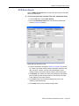
1
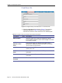
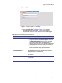
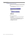
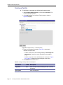
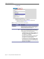
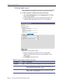
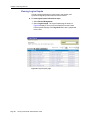
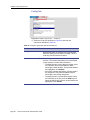
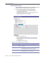
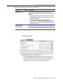
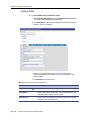
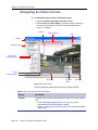
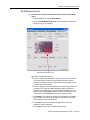
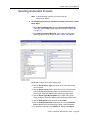
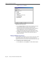
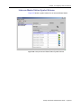
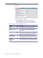
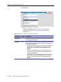
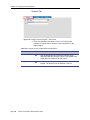
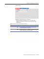
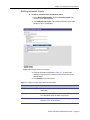
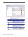
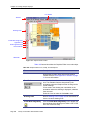
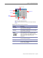
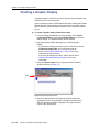
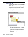
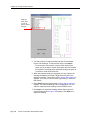
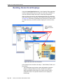
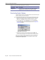
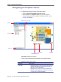
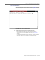
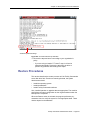
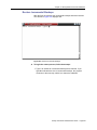
Chapter 15 Creating Graphic Displays
Using the Graphics Editor
The Graphics Editor allows you to associate symbol schemes to site
maps. The symbol scheme identifies icons that represent doors, cameras,
or other device in different alarm conditions. These icons are associated
with an event type and when an alarm is generated, the appropriate icon
displays on the site map.
For example, a scheme with icons representing doors in an alarm state
may include a:
•
gray door to represent the initial state
•
red door to represent a set condition
•
green door to represent a reset condition
When an alarm is generated at the specific door access point, the
appropriate icon for the state condition displays on the map. Refer to
Creating a Symbol Scheme on page 291 for more information.
If you create site maps and link them in a hierarchal arrangement, the
associated icons on each level also displays the icon in its alarm state
condition. Refer to Building Hierarchical Displays on page 320.
There are three ways to create a site map, which are:
•
Create map with the drawing tools provided by the Graphics
Editor.
- Using the drawing tools, such as circles, lines, polylines,
rectangles, and text entries, you can create a site map, or a
graphical representation of your facilities. Refer to Drawing
Tools on page 305 for more information.
•
Use an existing JPG or GIF graphics file.
- Most professional drawing applications usually have the
capability to save a drawing in a JPG or GIF format. Refer to
Create New Image Entry on page 302 for more information.
•
Import DXF drawings created with AutoCAD®.
- Site maps and drawings with a DXF extension can be imported
if they are saved in a DXF R12 format using AutoCAD. Refer to
Importing AutoCAD Drawings on page 314 for instructions.
To achieve the best results in your site map, draw the map as close to the
size of the window in which it will be displayed. If you are importing a JPG
or GIF graphic image file, try to size the image to fit the window in which it
will be displayed. Whenever possible, be consistent and keep all of your
displays the same size.
³
To open the Graphics Editor, follow these steps:
1. From the Facility Commander Launcher window, select Launch
and Graphics Editor, or select the Graphics Editor icon from the
Editors toolbar.
2. The Graphics Editor shown in Figure 177 on page 302 window
displays.
Facility Commander Administration Guide
Page 301