1
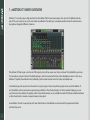
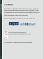
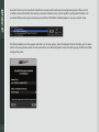
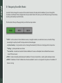
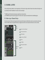
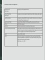
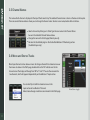
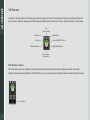
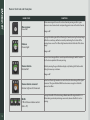
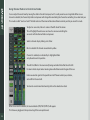
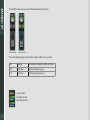
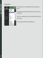
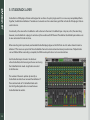
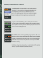
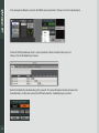
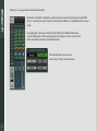
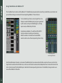
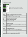
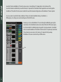
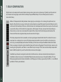
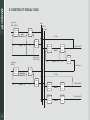
1
Table of Contents
Introduction3
About SoundGrid 3
1. eMotion St Mixer Overview
4
2. Setup Basics
5
2.1 Navigating SoundGrid Studio
7
3. Channel Layers
8
3.1. Mixer Layer Channel Strips
8
3.2 Channel Types
10
3.3 Channel Names
11
3.4 Mono and Stereo Tracks
11
3.5 Panners
12
3.6 Faders
15
4. Mixer Layer Control Modes
16
4.1 Preamp Control Mode
17
4.3 Route Control Mode
21
4.4 Sends Control Mode
24
5. StudioRack Layer
28
6. Sessions and Presets
33
7. Delay Compensation
35
8. eMotion ST Signal Flow
36
INTRODUCTION
Thank you for choosing the Waves eMotion ST mixer. In order to get the most out of this product, please take some time to read
this manual. We also suggest that you become familiar with the Waves support site: www.waves.com/support. There you will find
an extensive answer base, the latest tech specs, detailed installation guides, software updates, and current information about
authorization and registration.
About SoundGrid
SoundGrid is a scalable network infrastructure that provides a variety of cost-effective, high-quality solutions for recording studios.
It can be configured in many ways—with many hardware possibilities—to provide a very flexible audio work environment. This
framework is managed by the SoundGrid Studio Application, which configures the network, assigns and manages I/Os, controllers
and servers, and streams audio throughout the system. Any user, anywhere on the SoundGrid network, has access to any network
I/O device. Adding a SoundGrid DSP server moves processing away from the host application. This enables users to work with a
large number of plugins simultaneously and to create complex, low-latency monitor mixes from numerous sources. Key to these
features are the StudioRack plugin and the eMotion ST mixer.
The SoundGrid protocol is open to other developers of audio software and hardware. The list of SoundGrid-compatible tools is
therefore ever-growing.
3
1. eMOTION ST MIXER OVERVIEW
eMotion ST is a multi-purpose, high-quality mixer from Waves. With 8 mono/stereo inputs and up to 64 StudioRack channels,
plus 2 FX busses, 6 mix busses, and a main stereo mix, eMotion ST enables you to create personalized mixes for each musician,
alongside an altogether different studio mix.
The eMotion ST Mixer Layer is used to mix DAW outputs, mic and line sources, aux tracks, and more. The StudioRack Layer mixes
the low-latency outputs of up to 64 StudioRack plugins, which are routed to the Main and/or Headphones mixes. In this sense,
eMotion ST replaces the external mixer traditionally used to create monitor mixes for studios and headphones.
In the Mixer layer, each input and aux channel hosts up to 8 plugins. Almost every Waves plugin can be used with eMotion ST
and StudioRack, so there are enormous processing possibilities in the choice of plugins and in the number of plugins you can
use at the same time. eMotion ST operates within a SoundGrid network, so any available SoundGrid I/O device, whether hardware
or driver-based, local or remote, can provide inputs and outputs.
Since eMotion ST works in conjunction with SoundGrid Studio and StudioRack, we recommend that you become familiar
with how they work.
4
2. SETUP BASICS
The eMotion ST mixer is an integral part of the SoundGrid Studio application. Because it can process a very large number
of plugins simultaneously and perform low-latency monitoring, eMotion ST requires a DSP server. eMotion ST is installed
using the Waves SoundGrid Studio installer. A license is required, which you can authorize through the Waves License Center.
SoundGrid Studio is an application that launches at startup and is always available.
The “SG” icon on the top Menu Bar (Mac) or System Tray (Windows) confirms that SoundGrid Studio is running.
PC
Mac
Click on the SG icon to bring eMotion ST and SoundGrid Studio
to the front. You can also quit the SoundGrid Studio application from this menu.
You can also access eMotion ST by clicking the Mixer tab at the top of any SoundGrid Studio page.
5
SoundGrid Studio uses the SoundGrid Studio Wizard, a setup tool that automates the configuration process. When you first
assemble a network, the Wizard scans all ports, inventories network assets, and puts together a configuration that best suits
your needs. When you change the network port or click the SCAN button, the Wizard begins to scan your network setup.
The Wizard template menu then appears and offers a list of setup options. Select the template that best describes your hardware
devices and your production needs. You also can load the user-defined templates saved in the Settings page. The Wizard will then
configure the system.
6
2.1 Navigating SoundGrid Studio
SoundGrid Studio manages the resources of the SoundGrid network. All audio patched to eMotion ST passes through I/Os
(hardware and software) that are configured and set by SoundGrid Studio. The server you use for DSP processing and low-latency
recording is allocated by SoundGrid Studio.
The three tabs at the top of the page direct you to the three major sections:
■
S
ETUP – Use this section to find and allocate resources, manage the network, save and load sessions, and see that things
are working the way they should. The Setup section has three tab pages:
■
System Inventory – Assign network assets and manage the network. By far the most visited page in the Setup section.
■
Settings – System parameters are set here.
■
S
ession Info – Save and store SoundGrid Studio and eMotion ST sessions and templates. View installed software versions.
Access PDF user manuals.
■
PATCH – Create and modify patches between the eMotion ST mixer and outside I/Os, as well as patches between devices.
■
M
IXER – The eMotion ST mixer. The Mixer tab will not be available if a server is not assigned to the system or if an eMotion ST
license is missing.
7
3. CHANNEL LAYERS
Like most digital mixers, eMotion is built in logical layers. This allows for a large number of mixer channels without forcing the user
to scroll back and forth. The eMotion ST mixer has two channel layers:
■
■
A MIXER layer that includes multi-purpose input channels and auxiliaries.
A STUDIORACK layer with up to four pages of 16 channels each. Input comes directly from the StudioRack plugins.
3.1. Mixer Layer Channel Strips
The center sections of the mixer change with each mode, while the Input and Fader/Panner sections are common to all modes.
Panner and Fader sections change their function and appearance in the Sends mode when the mixer is Sends on Faders.
Input
Section
Name of selected channel
Preset name and menu
Channel name
Input source (L/R split)
Panner
Solo/Mute
Fader position indicator
Fader/Paner
Section
8
Fader
Functions Common to All Channels
9
Selected Channel
(top of page)
Displays name of the selected channel.
Channel Preset Name
(top of page)
Displays name of current preset for selected channel. Menu displays presets options.
Input Channel Name
Name of input channel. When the track is selected, the channel name is displayed in
the Selected Channel window as well.
Input Source (L/R split)
Source of audio as reflected in Patch page. Choose input source from menu.
Panners
Multi-function panners.
Solo/Mute
Latching. Solo clear button is located above the Main fader.
Fader Position/Peak Level Value Box
When a fader is selected, the value box indicates fader position. When a fader is not
selected, the value box indicates channel peak level. Also displays panner value when
panner is engaged. Click on the meter to clear peak indicator.
Faders
Range: -144 dB to +10 dB
Meters
Peak meters. Normally the value box above a fader shows the peak level. Meter
behavior (INP, PRE, POST) is determined in the SoundGrid Studio Settings window.
Click on the value box to clear peak hold.
Meter Range: -∞ to +10 dB
3.2 Channel Types
Input
channels
8 multi-purpose input channels (stereo/mono).
Input from any available SoundGrid-compatible I/O on a SoundGrid network.
Each channel accepts mic preamp, digital in, and line in, depending on I/O device.
Channels can output directly to any I/O on the SoundGrid network.
Each Input channel can insert up to 8 plugins.
Ch 1
Stereo
In most templates, stereo channel 1 is from DAW stereo out, but this can be re-routed.
Ch 2–8
Multi-purpose input channels.
Aux busses
StudioRack
channels
Main out
10
8 aux channels.
Each aux channel can insert up to 8 plugins.
Can be sent to Main out or Direct out.
Each aux channel can output directly to any I/O on the SoundGrid network.
Aux 1–2
Stereo FX busses. Aux 1–2 can send to Aux 3–8 for additional monitor processing.
Aux 3–8
Stereo aux busses. Typically used for headphone mixes.
1–32/64
Input channels directly from StudioRack. Designed for low-latency monitoring, not DAW
playback. Bussed directly to Main output or through sends to Aux. Refer to StudioRack manual
for details.
Stereo out, usually designed for control room monitor mix. All channels can buss to Main out.
3.3 Channel Names
The name of each channel is displayed at the top of the channel strip. The selected channel name is shown in the box on the top bar.
There are several Name windows where you can change the channel name. To enter a new name, double-click on the box.
■
■
■
S elect a channel by clicking on its fader. Type the new name in the Channel Name
box or in the Selected Channel Name window.
C
hange the name in the Patch page (Mixer layer only).
R
ename the StudioRack plugin in the StudioRack eMotion ST Monitoring section
(StudioRack layer only).
3.4 Mono and Stereo Tracks
Mixer layer channels can be stereo or mono. To change a channel from stereo to mono or
from mono to stereo in the Patch page, double-click on the “M” indicator next to the
channel name. The display will change from “M” to “L” and “R.” You can then rename the
two channels, which will appear independently on the eMotion ST input section.
You can also flip a track from stereo to mono in the
input section of an eMotion ST channel.
Mono/stereo changes made here are mirrored in the Patch page.
11
Mono/Stereo toggle
3.5 Panners
In each of its modes, eMotion ST features a panner for every channel. The mixer’s mono panners function as you’d expect them to
with any mixer, while the stereo panners offer unique possibilities, with several ways to move a stereo track within a sound image.
Pan
(Stereo Rotate)
Right Panner
Left Panner
Stereo Width (CTRL+click)
Rotation
Left Marker/Panner
Right Marker/Panner
Mono Panner/
Stereo Balance
Pan/Rotation Values
Pan and rotation values are indicated in the value box beneath the panner. Positive values indicate pan/rotation to the right.
Negative values indicate pan/rotation to the left. When a panner is not being manipulated, the value box shows fader/meter values.
Value Box
12
Panner Controls and Examples
FADER/STATE
Mono panner
Panned left
Balance
Panned right
FUNCTION
When a mono signal is bussed to a stereo channel, panning results in a gain
decrease in one channel and a corresponding gain increase in the other channel.
Range: ± 45°
Changes the relative gain of the left and right channels, moving the stereo image
within the soundscape, without necessarily maintaining the structure of the
moving stereo source. The left and right markers indicate the limits of the stereo
image.
Range: ± 45°
Moves a stereo image within a soundscape while retaining its width. Consider
this the stereo equivalent of mono panning.
Stereo rotation
Rotated left
Rotate by moving the green Rotation display or by holding the P button while
sliding the mouse up and down.
Range: ± 45°
Stereo rotation: reversed
Rotated right and L/R reversed
Width
Default Wide Narrow
13
CTRL+Click on rotation control
(Mac + PC)
When the left and right markers cross each other, the stereo image of the signal
is reversed. The green Rotation/Width area becomes orange to indicate this
reversed condition.
Changes the width of the stereo image. Maximum width: original width x 1.4.
When making an already wide image even wider, beware of artifacts such as
phasing.
FADER/STATE
Asymmetrical Stereo Panning
Right and left markers moved
separately
FUNCTION
Changes the width of the stereo image by moving only the left or right panner.
This is equivalent to using separate panners for left and right channels.
Pan asymmetrically by moving the Left or Right marker, or by clicking on the L or
R button and sliding the mouse up and down.
Pan and Rotation set to their zero positions.
Stereo panner and rotation
Default position
A yellow ring indicates that the panner is selected.
Panner is selected
To return a control to its default position, press ALT(OPT)+click.
14
3.6 Faders
Touch a fader to select its channel. The fader will change colors and the channel strip will highlight.
Solos are latching: they release only when clicked again.
Clear all solos with button above Main fader. Mutes are latching.
Channels that are not soloed are muted with a flashing indication
Peak level meters: Normally the value box above a fader shows the peak input level for that channel. Click on the
value box to clear peak hold. Hover over the value box or touch the fader to see the current fader position.
As with most Waves interfaces, ALT(OPT) + click on any knob or fader to return it to its zero position.
Meter behavior (PRE, POST, INP) is determined in the
SoundGrid Studio / Setup / Settings window.
15
4. Mixer Layer Control Modes
The Mixer layer is the input from outside sources. This layer can accept any input for which there is a SoundGrid-compatible I/O.
In some Wizard templates, channel 1 is a direct input from the DAW stereo out, but this is just a default that can be changed at any
time. Other sources may include microphone preamps, line inputs, or audio streams from other devices on the SoundGrid.
On the left side of the interface are four buttons used to access the different control modes of the Mixer layer:
PREAMP Control trim, gain, phase, and 48v phantom.
16
RACK
Insert up to 8 plugins to each aux and input channel
ROUTE
Select input source (A/B), bus to Main, or direct out.
SENDS
Send input and FX channels to auxiliaries.
4.1 Preamp Control Mode
The Preamp control mode is used to control preamps on hardware I/Os and to set gain from digital sources.
17
Control
Function
48v Phantom
On/Off
Preamp Gain Input
Controls analogue gain in an attached I/O device
that includes a controllable preamp.
Input Polarity
Mono channels have one polarity reverse button.
Stereo channels have two. Buttons are latching and
are colored green when engaged.
Digital Input Trim
Controls input level from digital sources. Separate
controls for L/R when input is stereo.
Range: -144 dB to +10 dB
4.2 Rack Control Mode
Use the Rack control mode to add, remove, control and manage plugins. Each input and aux channel
has a rack that will hold up to 8 plugins
Each rack has 8 plugin slots.
Signal flow is from top to bottom.
To add a plugin, click on an empty slot.
Choose a processor from the drop-down menu.
Use the same menu to remove,
enable/disable, or replace a plugin.
To insert the same plugin to all input channels, hold OPT/ALT as you select the plugin.
Aux channels behave in the same manner.
Change the sequence of plugins within a rack by dragging.
You can also drag a plugin (along with its parameter settings) from one channel rack to another.
18
When you select a plugin its window will open (see image).
To close the plugin, click on its name in the rack or on the
Close Window button.
Open a plugin that’s already in the rack by double-clicking on
its name in the slot. When you open a new plugin, the existing
window will close.
Unless bypassed or disabled, a plugin remains active
whether it is visible or not.
Use the green IN button to bypass the plugin.
The plugin’s rack slot is blue while in bypass.
The plugin’s name and insert location are displayed
in the upper left corner of the plugin window.
19
Other functions available in the INSERT PLUGIN menu:
20
Bypass
Places the selected plugin in bypass mode but does not remove it
from the processing chain (slot turns blue).
Disable Plugin
Removes the plugin from the processing chain but not from the
rack (slot turns dark green). Plugin settings are not lost.
Remove Plugin
Removes the plugin from the rack. Plugin settings are lost.
Copy
Copies the selected plugin and all of its parameter settings.
Paste (plugin name)
Pastes the copied plugin and all settings to the selected rack slot.
Paste Preset
Pastes copied plugin settings to the selected plugin.
Latency
Indicates latency of the selected plugin.
Rack Latency
Indicates total rack latency.
4.3 Route Control Mode
Use the Route control mode to set inputs and outputs for your mixer sessions.
Setting up eMotion ST’s signal flow is the same as in any other digital mixer. The template you choose in
the Wizard will usually provide In/Out assignments that work well for your eMotion ST and StudioRack
session. You should know, however, how audio flows through the SoundGrid Studio system. The Patch
page is where you establish and change connections between eMotion ST inputs and outputs and
SoundGrid Studio I/O devices, whether physical or virtual. Please refer to the signal flow diagram at the
end of this user manual.
Setting Mixer Channel Inputs and Outputs
To change eMotion ST inputs in the Route control mode, click on an input patch.
Stereo channels can have separate L/R inputs. Mono channels will show only one input.
Choose the source input device.
Choose the input channel(s).
To toggle a channel between stereo and mono, select “Flip to Mono” in the input dialogue menu.
21
Setting the channel outputs
Choose the I/O device and channel for direct output. You can select multiple
outputs on the same buss. From this menu you can also disconnect all routing for this channel.
You can select the Direct Output source of individual channels in the Patch page.
The output selector toggle switch is color-coded to reflect the output status.
22
INP
Orange
Input: before all processing; after input gain.
PRE
Light blue
Pre-fader, after processing
PST
Dark blue
Post-fader, after processing
PSP
Purple
Post-Pan, Post-fader, after processing
Buss to Mains
Use the MAIN button to send the output of a channel to the Main mix. Normally, the Main out will
be the studio mix, although you can change in this the Patch page. A channel can feed both the
Main mix and its direct out.
De-selecting the MAIN button will remove that channel from the Main mix but will not affect the
channel’s direct output.
Patches on the eMotion ST channel strip are mirrored in the SoundGrid Studio Patch page:
The eMotion ST Input A and B in the Route control mode coreespond to the Input A and Input B patch pages
Direction of patch
Hardware or software I/O devices
Source channels
Patch points
eMotion ST input channels
23
4.4 Sends Control Mode
Use the Sends control mode to control the aux send levels and panning for each of the 8 aux channel inputs.
eMotion ST channels 1–8 have 8 aux sends each.
Aux channels 1 and 2 have aux sends of their own to facilitate additional processing.
Set the level of an aux send by moving the slider within its cell. Relative gain is
indicated by the length of the slider.
To activate an aux send for a channel, click on the number immediately
above the slider. This area will turn green and ON will appear.
24
Using Channel Faders to Control Aux Sends
You can adjust the sends level by moving the slider in the cell it occupies, but it’s usually easier to use a large fader. When an aux
channel is selected, the channel strip faders and panners will change from controlling the channel to controlling its aux level and pan.
This mode is called “Sends on Fader.” The fader section of the mixer will be colored blue to remind you that you are in this mode.
To adjust an aux send, click on its name at the left side of the screen.
This will highlight the entire aux send row. You are now controlling the
aux sends with the channel faders and panners.
Select a channel strip by clicking on its fader.
Mix 4 is selected. All channels are outlined in yellow.
Channel 3 is selected, as indicated by its highlighted fader
and yellow channel strip outline.
The cell Chn3/Mix 4 is the one currently being controlled. Note that the cell is ON.
Its color indicates Input mode. Hovering above the fader reveals the gain of the aux.
Fader now controls gain for the specific send cell. Panner controls pan, rotation,
and width for the send cell.
To return to normal mixer functionality, click on the selected aux track.
When an aux send is selected, the Source Selector (PRE, POST, INPUT) will appear.
This three-way toggle sets the input routing of the aux input channel.
25
The ON/OFF controls the aux send of the selected channel strip only.
Channel Fader
Sends on Fader
The Source Selector toggle switch is color-coded to reflect aux input status.
INP
Orange
Input: before all processing; after input gain.
PRE
Light blue
Pre-fader, after processing
PST
Dark blue
Post-fader, after processing
Input, Aux OFF
Pre-fader, Aux ON
Post-fader, Aux ON
26
Copy Main Mix To
In the Channel Menu you can use the Copy Main Mix To function to speed up your
workflow.
Selecting this option will copy the Fader and Pan positions of the current Layer to one
of the eight sends.
This allows you to create headphone mixes based on the Main Mix and then customize
them individually.
This feature applies to both the Mixer and the StudioRack Layers.
27
5. StudioRack Layer
StudioRack is a DAW plugin software rack designed to run chains of up to 8 plugins each. It can run on any compatible platform.
Together, StudioRack and eMotion ST enable users to monitor and mix a low-latency path that includes all of the plugins that are
used in the mix.
Functionality is the same with a StudioRack as with a channel in the mixer’s StudioRack layer—they are, in fact, the same thing.
However, since StudioRack is a plugin, it controls only the one focused DAW channel. The eMotion StudioRack layer enables users
to view and control 16 tracks at a time.
When recording and in Input mode, each enabled StudioRack plugin bypasses the DAW and sends its audio channel stream to
eMotion ST. The mixer uses up to 64 of these StudioRack channels to create custom low-latency monitor mixes. Playback tracks
are not affected. When a recording is complete, the DAW monitor path returns to its normal condition.
Each StudioRack input channel is the direct out
of one StudioRack, which are assigned to aux sends using
the StudioRack Sends mode. Large faders are routed
to the Main mix.
The number of channels updates dynamically as
StudioRacks are added to or removed from eMotion ST.
There are four levels of 16 StudioRack tracks each.
Use the Page Navigate buttons to move from one
StudioRack level to another.
28
Establishing a Link Between StudioRack and eMotion ST
Set StudioRack to SoundGrid (SG) processing mode. This moves StudioRack processing to
the SoundGrid DSP server and establishes an initial connection between eMotion ST and
the StudioRack. eMotion ST will not recognize StudioRack channels that are set to
Local CPU. If the StudioRack Layer button is active but some StudioRacks do not appear in
the mixer, this probably means that the missing StudioRacks are not assigned to I/Os.
To populate channels in the StudioRack layer, set the StudioRack input channel to match the
driver input channel in the DAW track where the StudioRack is inserted. This enables you to monitor
the same input that you are recording. Track order is determined by the input channel number. Lower
channels are placed to the left of higher channels.
When StudioRack monitor status switches to Input, the I/O input signal is split into two paths. One path
goes to the DAW while the second goes directly to the inserted StudioRack, bypassing the DAW. When
StudioRack is in Input mode, the DAW monitor output is muted so that only the low-latency stream is
heard When the recording is finished, the monitor path switches back to the output of the DAW for
normal playback and mixing.
In both Playback and Input modes, audio passes through the same StudioRacks, with the same plugins
and settings, so you hear the same processing when recording and mixing.
29
In this example, StudioRack is inserted in the DAW channel named Vocal 1. I/O input A 3–4 is the selected input.
In the host DAW I/O preferences, the A 3-4 input is patched to Waves SoundGrid driver input 3-4.
Choose 3-4 as the StudioRack input channel.
Name the StudioRack by double-clicking in the name cell. This name will become the channel name in the
StudioRack layer. Use the same name as the DAW track where this StudioRack plugin is inserted.
30
eMotion ST is now populated with StudioRack channels.
Remember, StudioRack is designed to enable a low-latency monitor path by bypassing the DAW
when it is recording. For audio to pass from StudioRack to eMotion ST, StudioRack must be in Input
mode.
During playback, audio comes directly from the DAW, and StudioRack behaves like
a regular DAW plugin, with the same signal path as all plugins. Audio is not sent to the
mixer (a condition indicated by the Playback button).
If a StudioRack does not send audio
to the mixer, it is likely in Playback mode.
31
Using StudioRack with eMotion ST
The StudioRack Sends section and the eMotion ST StudioRack layer are precisely the same thing. StudioRack aux send levels and
pan and fader settings are mirrored in the corresponding eMotion ST mixer channel.
The StudioRack Input fader is akin to Digital Trim in the
Preamps mode of the Mixer layer. Input gain is governed
by this control, so all post-StudioRack gains, including
Input mode, are affected by this fader
StudioRack and eMotion ST switch from PB to INPUT
during low-latency recording and monitoring.
Monitor condition is indicated on the StudioRack
monitor section and on the corresponding channel strip.
Monitoring mode
monitoring indicators
Each StudioRack input channel is an instance of StudioRack which can route audio to the Main output and to aux sends. Use the
large faders to route audio to the Main mix; use the aux send faders to route audio to headphone mixes. Since each channel in the
Sends Control mode of the StudioRack layer is identical to the corresponding Sends view of a StudioRack, changes made in one
view will be reflected in the other.
32
6. Sessions and Presets
Use the Channel menu to save, import, export and move plugin settings.
This menu can also be used to save and load sessions for SoundGrid Studio.
Factory Presets
Loads manufacturer presets.
User Presets
Lists all eMotion ST user-created channel presets that can be opened in any channel.
Import from File
Imports a channel preset from a file.
Presets are interchangeable between eMotion ST, MultiRack, and StudioRack.
Save
Saves preset of current settings. Overwrites the existing file.
Save As
Saves the preset. Creates a new file with a new name.
Rename Preset
Renames preset. Does not create new file.
Export to File
Saves a preset to an external file so that it can be imported to another eMotion ST system or to MultiRack.
Copy
Creates a copy of the current preset.
Save Session
Saves the entire SoundGrid Studio session state, including mixer status. Identical to saving in the SoundGrid
Studio Session Info page.
Save Session As
Saves entire SoundGrid Studio session under a new name.
Load Session
Loads a SoundGrid Studio session from a file.
Save Template As Saves session with all settings except configuration. Will appear in the Templates menu.
Load Template
Loads a saved template. All session settings except configuration are loaded. When the template is launched,
SoundGrid Studio will search for necessary network assets and will prompt if they cannot be found.
Copy Main Mix To Copies the Fader and Pan positions of the current Layer to a selected send
33
SoundGrid Studio and eMotion ST share the same sessions. Since eMotion ST is dependent on the structure of the
SoundGrid network established by SoundGrid Studio, it’s important that the details of both applications are stored together.
An eMotion ST/SoundGrid Studio session includes the SoundGrid network configuration and the eMotion ST mixer snapshot.
A session saved in SoundGrid Studio or eMotion ST does not include StudioRack settings. StudioRack is a
DAW plugin, so its settings are saved and will open with the DAW session.
However, you can save the eMotion ST session through StudioRack by pressing the
Save button in the StudioRack monitor sends section. When the DAW session opens,
it will instantiate the StudioRack plugin along with its plugin parameters. StudioRack
will in turn load the eMotion ST/SoundGrid Studio session in its previously saved state.
If you choose to save sessions in this manner, it’s important that you keep
the eMotion ST sessions current with your DAW sessions.
Save
34
7. Delay Compensation
Digital mixers must compensate for uneven latencies among various input sources and processors. Typically, input channels and
aux channels host many plugins, each of which are likely to impose different delays. The sum of these processes results in
inconsistent latency.
eMotion ST compensates for delays between streams going to a summing buss. For summing, all input channels are
aligned with each other as a group. Aux channels are also aligned as a group. When input channels with delay are sent to
aux channels that have delays of their own, further latencies must be compensated for when these input and aux channels
are sent to the Main out. The limit for this compensation is 4096 samples. This does not mean that the total delay in a
channel or buss or main buss cannot exceed 4k samples. Rather, it means that the total compensation between the
channels with the least and greatest delay cannot be more than this figure.
If this delay compensation limit is exceeded, a red warning will appear above the Main fader. This indicates that one or
more inputs to a summing mix buss are not fully delay-compensated, which can result in artifacts such as phasing. In
such cases, you would probably need to reduce the latency of at least one rack. Open the eMotion Rack control mode.
Click on any plugin in the rack in order to check the latency of the rack and the plugin. If the rack’s latency is excessive, try
rerouting your signal path to see if there is a more efficient way to arrange it. If this does not reduce delay compensation
below the 4096 sample limit, you will need to disable or remove certain plugins.
StudioRack Layer channels are aligned to each other in the Main mix bus. Latencies introduced by hosted plugins in
StudioRack are taken into account. In StudioRack Playback mode, audio does not pass through the eMotion ST mixer.
When playing back recorded material, StudioRack is a DAW plugin and its delay is governed by the DAW—it is not affected
by eMotion ST latency considerations.
35
8. eMotion ST Signal Flow
Input From
H/W or S/W IO
Channel
Rack
Process
Input
Channels 8-1
Sends
INP
PRE
Fader
+
Pan
PST
INP
To Main
Fader
+
Pan
Direct Out To
H/W or S/W IO
Input From
H/W IO
Studio
Rack
Process
Main
Aux 2-1
Aux 8-3
Channel
Rack
Process
INP
Sends
PRE
PST
Fader
+
Pan
Send To Aux 3-8
StudioRack
Channels 64-1
Sends
PRE
Fader
+
Pan
PST
To Main
Fader
+
Pan
Channel
Rack
Process
Channel
Rack
Process
36
Aux 2-1
To H/W or S/W IO
Fader
+
Pan
To H/W or S/W IO
Aux 8-3
Fader
+
Pan
To H/W or S/W IO
Aux 8-3
Fader
+
Pan