1
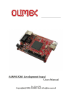
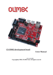
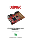
SAM9-L9260 development board
Users Manual
Rev.D, September 2009
Copyright(c) 2009, OLIMEX Ltd, All rights reserved
INTRODUCTION:
SAM9-L9260 is a low cost development platform with ARM9
microcontroller, 64MB SDRAM and 512MB NAND Flash. The board has
Ethernet 100Mbit controller, USB host, USB device, RS232 and 40 pin
extension port with all unused SAM9260 ports available for add-on boards.
SAM9-L9260 has waste amount of Flash and RAM and runs Linux,
WindowsCE and other RTOS natively. The on-board RTC clock is equipped
with a 3V Li backup battery.
BOARD FEATURES:
-
MCU: AT91SAM9260 16/32 bit ARM9™ 200MHz operation
50MHz system (main) clock
standard JTAG connector with ARM 2x10 pin layout for
programming/debugging with ARM-JTAG
64 MB SDRAM
512MB NAND Flash (seen in Linux as silicon drive)
Ethernet 100Mbit connector
USB host and USB device connectors
RS232 interface and drivers
SD/MMC card connector
one user button and one reset button
one power and two status LEDs
on board voltage regulator 3.3V with up to 800mA current
single power supply: 5V DC required
power supply filtering capacitor
18.432 Mhz crystal on socket
extension header
PCB: FR-4, 1.5 mm (0,062"), soldermask, silkscreen component print
Dimensions: 100 x 80 mm (3.94 x 3.15")
ELECTROSTATIC WARNING:
The SAM9-L9260 board is shipped in protective anti-static packaging. The
board must not be subject to high electrostatic potentials. General practice
for working with static sensitive devices should be applied when working
with this board.
BOARD USE REQUIREMENTS:
Cables:
1.8 meter USB A-B cable to connect with USB host.
Null modem RS232 female – female to connect with PC COM
port.
Hardware: ARM-JTAG, ARM-USB-OCD or other compatible tool if you
want to program this board with JTAG, usually with linux
installed you can develop without the need for JTAG.
Software:
The CD contains Linux 2.6 complete with source and binary in
CD.
BOARD LAYOUT:
SCHEMATIC:
PROCESSOR FEATURES:
SAM9-L9260 board uses CPU AT91SAM9260 from Atmel® with the
following features:
- Incorporates the ARM926EJ-S™ ARM® Thumb® Processor
o DSP Instruction Extensions, ARM Jazelle® Technology for Java®
Acceleration
- External Bus Interface (EBI)
o Supports SDRAM, Static Memory, ECC-enabled NAND Flash and
CompactFlash®
- USB 2.0 Full Speed (12 Mbits per second) Device Port
o On-chip Transceiver, 2,432-byte Configurable Integrated DPRAM
- USB 2.0 Full Speed (12 Mbits per second) Host
- Ethernet MAC 10/100 Base T
o Media Independent Interface or Reduced Media Independent
Interface
o 28-byte FIFOs and Dedicated DMA Channels for Receive and
Transmit
- Bus Matrix
o Six 32-bit-layer Matrix
o Boot Mode Select Option, Remap Command
- Fully-featured System Controller, including
o Reset Controller, Shutdown Controller
o Four 32-bit Battery Backup Registers for a Total of 16 Bytes
o Clock Generator and Power Management Controller
o Advanced Interrupt Controller and Debug Unit
o Periodic Interval Timer, Watchdog Timer and Real-time Timer
- Reset Controller (RSTC)
o Based on a Power-on Reset Cell, Reset Source Identification and
Reset Output Control
- Clock Generator (CKGR)
o Selectable 32,768 Hz Low-power Oscillator or Internal Low
Power RC Oscillator on Battery Backup Power Supply, Providing
a Permanent Slow Clock
o 3 to 20 MHz On-chip Oscillator, One up to 240 MHz PLL and
One up to 130 MHz PLL
- Power Management Controller (PMC)
o Very Slow Clock Operating Mode, Software Programmable Power
Optimization Capabilities
o Two Programmable External Clock Signals
- Advanced Interrupt Controller (AIC)
o Individually Maskable, Eight-level Priority, Vectored Interrupt
Sources
o Three External Interrupt Sources and One Fast Interrupt
Source, Spurious Interrupt Protected
- Debug Unit (DBGU)
o 2-wire UART and Support for Debug Communication Channel,
Programmable ICE Access Prevention
- Periodic Interval Timer (PIT)
o 20-bit Interval Timer plus 12-bit Interval Counter
- Watchdog Timer (WDT)
o Key-protected, Programmable Only Once, Windowed 16-bit
Counter Running at Slow Clock
- Real-time Timer (RTT)
o 32-bit Free-running Backup Counter Running at Slow Clock
with 16-bit Prescaler
-
-
-
-
-
-
-
-
One 4-channel 10-bit Analog-to-Digital Converter
Three 32-bit Parallel Input/Output Controllers (PIOA, PIOB, PIOC)
o 96 Programmable I/O Lines Multiplexed with up to Two
Peripheral I/Os
o Input Change Interrupt Capability on Each I/O Line
o Individually Programmable Open-drain, Pull-up Resistor and
Synchronous Output
o – High-current Drive I/O Lines, Up to 16 mA Each
Peripheral DMA Controller Channels (PDC)
One Two-slot MultiMedia Card Interface (MCI)
o SDCard/SDIO and MultiMediaCard™ Compliant
o Automatic Protocol Control and Fast Automatic Data Transfers
with PDC
One Synchronous Serial Controller (SSC)
o Independent Clock and Frame Sync Signals for Each Receiver
and Transmitter
o I²S Analog Interface Support, Time Division Multiplex Support
o High-speed Continuous Data Stream Capabilities with 32-bit
Data Transfer
Four Universal Synchronous/Asynchronous Receiver Transmitters
(USART)
o Individual Baud Rate Generator, IrDA® Infrared
Modulation/Demodulation, Manchester Encoding/Decoding
o Support for ISO7816 T0/T1 Smart Card, Hardware
Handshaking, RS485 Support
o Full Modem Signal Control on USART0
Two 2-wire UARTs
Two Master/Slave Serial Peripheral Interfaces (SPI)
o 8- to 16-bit Programmable Data Length, Four External
Peripheral Chip Selects
o Synchronous Communications
Two Three-channel 16-bit Timer/Counters (TC)
o Three External Clock Inputs, Two Multi-purpose I/O Pins per
Channel
o Double PWM Generation, Capture/Waveform Mode, Up/Down
Capability
o High-Drive Capability on Outputs TIOA0, TIOA1, TIOA2
One Two-wire Interface (TWI)
o Master, Multi-master and Slave Mode Operation
o General Call Supported in Slave Mode
IEEE® 1149.1 JTAG Boundary Scan on All Digital Pins
Required Power Supplies:
o 1.65V to 1.95V for VDDBU, VDDCORE and VDDPLL
o 1.65V to 3.6V for VDDIOP1 (Peripheral I/Os)
o 3.0V to 3.6V for VDDIOP0 and VDDANA (Analog-to-digital
Converter)
o Programmable 1.65V to 1.95V or 3.0V to 3.6V for VDDIOM
(Memory I/Os)
AT91SAM9260 Block Diagram
MEMORY MAP:
POWER SUPPLY CIRCUIT:
The power supply for SAM9-L9260 must be regulated +5VDC. Please apply
exactly 5V as the same power line goes to USB hosts and if you apply over 5V
you will damage your USB devices attached to the host.
The current consumption is typical 250mA with 180 MHz clock of SAM9260
and 90MHz clock of external bus.
For the RTC there is a battery backup power supply from a small 3V Li
battery type CR2032.
RESET CIRCUIT:
SAM9-L9260 reset circuit is made with a 4.7k pull-up resistor and a RST
button connected to GND.
CLOCK CIRCUIT:
Quartz crystal Q1-18.432Mhz is connected to SAM9-L9260 Xin and Xout
pins.
Quartz crystal Q2-32768Hz is connected to SAM9-L9260 Xin32 and Xout32
pins.
JUMPER DESCRIPTION:
SMD jumper description
3.3V_E
Enable the main 3.3V regulator VR1(3.3V)-RC1587
Default state - closed
3.3V_MCU_E Enable 3.3V to the SAM9260 microcontroler.
Default state - closed
1.8V_MCU_E Enable 1.8V to the SAM9260 microcontroler.
Default state - closed
BDS_E
BounDary Scan Enable. The BDS_E jumper is used to select
the JTAG boundary scan when JTAGSEL pin asserted at a
high level (tied to VDDBU). This pin integrates a permanent
pull-down resistor of about 15KΩ to GNDBU. When BDS_E is
open JTAG function is selected.
Default state – open
TCK-RTCK Connects RTCK and TCK pins of SAM9260.
Default state open
WPE Connects PC4(pin62) to Write Protection pin of SD/MMC socket. If WP
function is not used, WPE jumper has to be open and PC4 is
available of EXT connector pin 20.
Default state - closed
CPE Connects PC8(pin61) to Card Present pin of SD/MMC socket. If CP
function is not used, CPE jumper has to be open and PC8 is
available of EXT connector pin 14.
Default state - closed
NTRST_E
When the NTRST_E jumper is closed – connects NTRST(pin 35)
to JTAG connector (pin3).
Default state - closed
WP_SFLASH_E
When the WriteProtect_SerialFLASH_Enable jumper is
closed it allows to protect the boot code written to
U5(AT45DB161D-SU) flash memory.
Default state open
WP_NFLASH_E
When the WriteProtect_NandFLASH_Enable jumper is
closed user can't write in the NAND flash.
Default state open
A2_L/A2_H Connects Address2(A2)pin of U8-24LC256 memory (default not
mounted) to logical 0 or logical 1, i.e. A2_L/A2_H define the
memory address of I2C bus.
Default state - open
PTH jumper description:
BMS_LOW
Boot Mode Sellect _ LOW jumper select the boot memory
External memory or embedded ROM. When BMS_LOW is
closed – BMS pin is logical 0, otherwise – logical 1.
Default state - open
BMS_LOW
BAT/EXT
The BATerry/EXTernal jumper defines the power source which
supplies the backup logic from VDDBU - pin 47.
BAT position – 3V Li battery type CR2032 plugged in BAT holder
supplies VDDBU through backup VR3(1.8V) MCP1700T1802E/MB voltage regulator.
EXT position – The VDDBU is powered from main 1.8V voltage
regulator VR2(1.8V) – LM1117.
Default state
BAT/EXT
INTRC/EXTCLK
The INTRC/EXTCLK jumper defines the SAM9260 slow clock source.
INTRC position – internal RC slow clock oscilator is selected
EXTCLK position – external 32768 crystal is used for SAM9260 slow
clock.
Default state
INTRC/EXTCLK
RXD1/DRXD
The RXD1/DRXD jumper defines which pin - RXD1 or DRXD - is
connected to the RS232 driver (ST3232), i.e. the board allows
comunication with PC COM port through RXD1 or DRXD.
RXD1 position – RXD1 function of SAM9260 pin 18 is tied to
pin12(R1OUT) of U6(ST3232).
DRXD position – DRXD function of SAM9260 pin 21 is tied to
pin12(R1OUT) of U6(ST3232).
Default state
RXD1/DRXD
TXD1/DTXD
The TXD1/DTXD jumper defines which pin - TXD1 or DTXD - is
connected to RS232 driver (ST3232), i.e. the board allows
comunication with PC COM port through TXD1 or DTXD.
TXD1 position – TXD1 function of SAM9260 pin 17 is tied to
pin11(T1IN) of U6(ST3232).
DTXD position – DTXD function of SAM9260 pin 22 is tied to
pin11(T1IN) of U6(ST3232).
Default state
TXD1/DTXD
PHY_PDE/PHY_PDCTRL
PHY_PDE position – The PHY chip U7(KS8721BL) enter to power
down mode.
PHY_PDCTRL position – The PHY chip power down mode is controled
from SAM9260 PC1(pin58).
OPEN position – The PHY chip is alwаys enabled.
Default state- open
NANDF_E
PHY_PDE/PHY_PDCTRL
The NANDFlash_Enable allows PC14/NAND_CS pin of
SAM9260 to control CE pin of NAND FLASH memory
U3(K9F4G08UXM). If the board has to boot from NAND flash
the NANDF_E jumper must be closed.
Default state- close
NANDF_E
DF_EThe DataFlash_Enable allows PC11/SPI0_NPCS1 pin of SAM9260 to
control CS pin of serial Data Flash memory U5(AT45DB161DSU). If the board has to boot from Data Flash the DF_E jumper
must be closed.
Default state- close
INPUT/OUTPUT:
DF_E
RS232_0 is used as terminal in Linux, so you can connect to PC
hyperterminal for instance and work at command prompt.
The cable between SAM9-L9260 and PC must be female – female, null
modem type. Terminal settings are 115200 , 8bits, 1stop, no parity, no flow
control.
User button with name BUT – connected to SAM9260 pin127 PC15(IRQ1);
Status green LED with name STAT (SAM9260 pin185 PA6). The default
Linux installation ties it to NAND activity and lights it up whenever NAND is
accessed.
Power supply yellow LED with name PWR_LED indicates the state of
SAM9260. The default Linux installation links it to the CPU load and is
blinking it with a distinctive heartbeat pattern.
The LED PWR_5V (red) indicates +5V present on the board when it's on.
EXTERNAL CONNECTOR DESCRIPTION:
JTAG:
The JTAG connector allows a software debugger to talk via a JTAG (Joint
Test Action Group) port directly to the core. Instructions may be inserted and
executed by the core thus allowing SAM9260 memory to be programmed
with code and executed step by step by the host software.
For more details refer to IEEE Standard 1149.1 - 1990 Standard Test Access
Port and Boundary Scan Architecture and SAM9260 datasheets and users
manual.
Pin #
Signal Name
Pin #
Signal Name
1
VCC
2
VCC
3
ICE_NTRST
4
GND
5
TDI
6
GND
7
TMS
8
GND
9
TCK
10
GND
11
RTCK
12
GND
13
TDO
14
GND
15
ICE_NRST
16
GND
17
NC
18
GND
19
NC
20
GND
UEXT
Pin #
Signal Name
1
VCC
2
GND
3
PB8
4
PB9
5
PA24_TWCK
6
PA23_TWD
7
PB0(SPI1_MISO)
8
PB1(SPI1_MOSI)
9
PB2(SPI1_SPCK)
10
PB3(SPI1_NPCS0)
USB_D:
Pin #
Signal Name
1
+5V
2
USBDM
3
USBDP
4
GND
USB_A:
Pin #
Signal Name
1
+5V
2
HDMA
3
HDPA
4
GND
LAN:
Pin #
Signal Name
1
TD+
2
TD-
3
RD+
4
GND_LAN
5
GND_LAN
6
RD-
7
GND_LAN
8
GND_LAN
LED
Color
Usage
Right
Yellow
Activity
Left
Green
100MBits/s (Half/Full duplex)
EXT:
SAM9-L9260 has an ext_connector with 40 pins
Pin #
Signal Name
Pin #
Signal Name
1
3.3V
2
3.3V
3
PC15
4
+5V
5
PB0
6
PC14_NANDCS
7
PB1
8
PC13_RDYBSY
9
PB2
10
PC10
11
PB3
12
PC9
13
PB4
14
PC8
15
PB5
16
PC7
17
PB8
18
PC6
19
PB9
20
PC4
21
PB10
22
PB31
23
PB11
24
PB30
25
PB16
26
PB29_CTS1
27
PB17
28
PB28_RST1
29
PB18
30
PB27
31
PB19
32
PB26
33
PB20
34
PB25
35
PB21
36
PB24
37
PB22
38
PB23
39
GND
40
GND
RS232:
Pin #
Signal Name
1
NC
2
RXD
3
TXD
4
6
5
GND
6
4
7
RTS
8
CTS
9
NC
MECHANICAL DIMENSIONS:
SOFTWARE development:
Overview
The board comes with Linux preloaded in the NAND and DATAFLASH flash
memories. It's based on a custom-built kernel and a Debian 5.0 userland. To use it, connect a
null-modem cable to the board and to a serial port on your computer, start a terminal program
(e.g. HyperTerminal on Windows, minicom on Unix systems) and configure it to use a
115200 baud rate, 8 data bits, 1 stop bit and no parity and no flow control. Then apply power
to the board (use a 5VDC regulated power supply with at least 500mA output current) and
you should see the board start-up messages. The default root password is 'olimex'.
Restoring the default bootloader and kernel
If for some reason you need to restore the default factory configuration of the board,
the procedure is as follows:
First install the ATMEL AT91-ISP v1.12 package which comes on the disk. Reboot
the computer if needed.
Remove the NANDF_E and DF_E jumpers on the SAM9-L9260 board and power it
up. Connect an USB cable to the USB_D connector on the board and wait for the board to be
detected (the driver should already be installed by the AT91-ISP v1.12 package, so let
Windows search for it).
Close the NANDF_E and DF_E jumpers and run the
at91sam9260_demo_linux_dataflash.bat file from the sam9-l9260-samba directory. After a
while the log file will be displayed and the system should be restored to the default state.
WARNING! This procedure erases the whole NAND flash and the root filesystem will also
be destroyed and reset to its factory defaults in the process.
After a successful script execution the bootloaders and the Linux uImage will be
placed in DATAFLASH and the root filesystem will be placed in NANDFLASH. The reason
to boot from DATAFLASH is an AT91SAM9260 chip errata issue.
Alternative on-board root filesystem restore procedure
Boot-up the board with an alternate root filesystem (e.g. a USB flash drive, NFS
exported filesystem...) and use the following command (assuming that the rootjffs2.img file is
available in /)
sam9-l9260:~# flash_eraseall -j /dev/mtd1
sam9-l9260:~# nandwrite -a /dev/mtd1 /rootjffs2.img
You may get some errors about bad blocks not being erased - this is normal and is related to
the principle of operation of NAND flashes. After the process is completed, reboot the board.
Running with another root filesystem
You may choose to use another media for the root filesystem for various reasons more capacity, faster access, etc. A complete root tree is archived in the sources/sam9-l9260-
rootfs.tar.bz2 file. It can be extracted to an empty ext3 partition on an USB drive or to some
NFS exported directory. Then you need to tell the kernel where to find the root - this is
accomplished by interrupting the u-boot process at the "Hit any key to stop autoboot:..."
prompt and setting the bootargs variable. For example, to boot from a USB flash drive, the
command is:
U-Boot> setenv bootargs mem=64M console=ttyS0,115200 root=/dev/sda1 rootdelay=10
and for booting from an NFS server at adress 192.168.0.75:
U-Boot> setenv bootargs mem=64M console=ttyS0,115200 root=/dev/nfs
nfsroot=192.168.0.75:nfsroot,proto=tcp ip=192.168.0.222:192.168.0.75
Please see the linux-2.6.xx/Documentation/filesystems/nfsroot.txt file from the Linux sources
directory.
Toolchain
The sources for the bootloaders and the Linux kernel must be compiled under Linux
PC host. We don't intend to support Cygwin.
The projects were compiled using Codesourcery G++ lite 2009q1, freely available
from http://www.codesourcery.com. A convenience tarball is provided that contains the
Codesourcery binaries along with some useful shell scripts. This tarball must be extracted in
user's home directory. Example:
cd $HOME
tar xjf codesourcery-toolchain-2009q1-repack.tar.bz2
The latter will create a directory
$HOME/bin/codesourcery-armgcc-2009q1
Along with some shell scripts that must be sourced before compilation:
$HOME/bin/linux_cross_compile.sourceme
$HOME/bin/bootloader_cross_compile.sourceme
The latter shell scripts would add the cross compiler binaries to the PATH environment
variable and will set the ARCH and CROSS_COMPILE variables to arm and arm-nonelinux-gnueabi-/arm-none-eabi- respectively.
Building a custom kernel
The recommended build method is to use a cross-compiler. Building natively should
also work but would be very time-consuming. At the moment of this writing, the current
kernel version is 2.6.31-rc3, for which a pre-patched tarball is provided. After extracting the
sources in a temporary directory you can build the default kernel by typing
$ source $HOME/bin/linux_cross_compile.sourceme
$ make sam9_l9260_defconfig
$ make uImage
After the compilation, the kernel should be available at arch/arm/boot/uImage. If the
build process fails to detect the mkimage program then you need to get it and put it in your
PATH. The easiest way is to compile U-Boot and fetch it from the u-boot/tools subdirectory.
The new kernel can be transferred to the board by various means - e.g. use the board
restoration process and change the kernel in there, tftpboot-ing the board, etc.
Convenience GIT patches for the kernel are also provided in a separate tarball.
Building the bootstrap binary
Extract the sources from source/at91bootstrap-2.4-olimex.tar.bz2 to your working
directory and issue the following commands:
$ source $HOME/bin/bootloader_cross_compile.sourceme
$ make sam9_l9260_defconfig
If everything is correct, the resulting binary file will be located in the /binaries
directory.
Building U-Boot
Extract the sources from source/u-boot-olimex-git20090716.tar.bz2 and issue:
$ source $HOME/bin/bootloader_cross_compile.sourceme
$ make sam9l9260_config
$ make
Cross-compiling a simple "hello world" example
Extract one of the provided cross-compilers on your host system and add it to the
PATH variable. Use the cross-compiler to build the example, then transfer it to the board by
e.g. USB flash drive, http download etc.
Example commands:
----- On the host system ----$ source $HOME/bin/linux_cross_compile.sourceme
$ cat > hello.c
#include <stdio.h>
int main(void)
{
unsigned int i;
printf("\r\nProba proba ");
for (i=0; i<10; i++)
printf("\r\n%d", i);
return 0;
}
^D
$ arm-none-linux-gnueabi-gcc -o hello hello.c
$ cp hello ~/htdocs/
----- On the board ----~ # wget http://192.168.0.xx/hello
~ # chmod 777 hello
~ # ./hello
Proba proba
0
1
....
Using JTAG to program the board
A sample project is provided in the “TEST_BUTT” directory that demonstrates how
to write a project that runs directly on the core, without the need of an operating system. It
was developed using IAR Embedded Workbench for ARM ver. 4.42A with a Segger J-Link
JTAG adapter
Common Questions
Q: When booting from the internal NAND flash the board seems to hang at "INIT: version
2.86 booting" and/or "Activating swap...done" lines
A: When mounting the JFFS2 root filesystem, the system performs a consistency check
(similar to fsck). This almost blocks all access to the nand flash and the system appears to
hang. Please wait - on a first boot of a new filesystem this could take up to 5 minutes and is
considered normal.
Q: There are messages "Buffer I/O error on device mtdblock0, logical block 0;end_request: I/
O error, dev mtdblock0, sector 0" during boot-up. Is there a problem on the board?
A: These messages indicate incorrect OOB records in the part of the flash where the
bootloader is stored and are due to the version of SAM-BA which is used to write the various
parts of the bootloader. For all pracical reasons the above messages are harmless.
Q: The I/O operations are slow when using the on-board nand flash or USB flash drive.
A: When doing a sequential read/write (e.g. one single large file) flash memories can be fast.
When reading/writing many small files the performance will be really low.
Q: How to boot from the on board DataFlash?
A: Make sure that NANDF_E jumper is not connected and DF_E jumer is connected. If the
dataflash has been correctly programmed, the board should start up.
Q: Is the SD/MMC card supported?
A: The SD/MMC card is fully supported, including detection of card insertion/removal and
write lock
Q: What do the two LED's indicate?
A: These two leds are driven by default by the linux LED driver. The STAT LED is switched
on NAND memory access. The PWR_LED LED is blinking with a distinctive heartbeat
pattern and a frequency that depends on the system load.
Q: The system time is lost after reset, how to avoid that?
A: Unfortunately the Linux AT91SAM9 RTC driver is not yet operational. When it is
completed, you would just need a standard 3V battery at the socket at the back of the board.
Until then please set the date manually or use a network time synchronization utility as
ntpdate. Note also that AT91SAM9260 chips have a RomBOOT errata issue where
RomBOOT incorrectly resets the RTT on every system reset.
Q: What kernel options do I need for NFS root filesystem support?
A: These options must be enabled (NOT AS MODULES):
- CONFOG_NFS_FS
- CONFIG_ROOT_NFS
- CONFIG_NET_ETHERNET
- CONFIG_IP_PNP
- CONFIG_IP_PNP_RARP
- CONFIG_IP_PNP_BOOTP
- CONFIG_IP_PNP_DHCP
Q: I have built my own uImage kernel image. Now how do I install modules?
A: First you need to place the target root filesystem somewhere on the build machine.
Remember to use "root" for all extraction/manipulation procedures! Then enter the Linux
source directory (where you typed "make uImage") and type:
$ # compile
$ make modules
$ # and then install as root!
$ make INSTALL_MOD_PATH=/path/to/target/root/filesystem modules_install
Note that the path must be to the root filesystem's root directory, and NOT the "lib" or
"lib/modules" subdirectories!
Q: How do I use TFTP to boot my custom compiled kernel? I want to skip the whole writeuImage-to-flash-then-boot process and instead use something much more quicker.
A: You need to set the board's IP address, the TFTP server IP address and a few more U-Boot
environment variables. So stop U-Boot by pressing ENTER during the countdown after reset,
and type the following lines in the U-Boot prompt:
u-boot$ setenv ipaddr 192.168.0.239
u-boot$ setenv netmask 255.255.255.0
u-boot$ setenv serverip 192.168.0.225
u-boot$ setenv bootcmd tftpboot \; bootm
u-boot$ setenv bootfile uImage
u-boot$ boot
The above example assumes you board gets IP 192.168.0.239, your TFTP server has IP
192.168.0.225, and the kernel image filename is "uImage".
Q: I can't run user programs under Linux 2.6.26 due to "Illegal Opecode".
A: See http://forum.sparkfun.com/viewtopic.php?t=12800 . Recent SAM9-L9260 CDs don't
have this problem.
Q: I get "mmap" errors while trying to run apt-get
A: See http://glomation.net/smf/index.php?topic=5.0 for more information. RootFS images
with recent CDs have this fix applied.
Q: What drivers are included in the provided Linux kernel for SAM9-L9260?
A: The kernel includes drivers for:
- MTD NAND
- Ethernet
- USB host
- USB gadget device
- Two serial ports
- SD/MMC
- RTC (but see AT91SAM9260 errata - RTC is reset with each system reset)
Q: I get "macb tx underrun" errors.
A: Unfortunately this a limitation of the AT91SAM9260 SoC. A simple google search reveals
patches that in some way resolve this but they are not yet in mainline. Another option is to
slow down the Ethernet interface, which somewhat mitigates the issue:
sam9-l9260$ ethtool -s eth0 speed 10 autoneg off
If you don't have ethtool then you can install it with apt-get.
Q: Is there a GUI option for SAM9-L9260?
A: Vishnu Tadepalli has added a kernel driver for MOD-NOKIA6610 connected to SAM9L9260 UEXT port, and has ported NanoX for this combo :) See the nanx-sam9-l9260.zip and
linux-2.31-rc8-olimex-patches.zip archives. Please contact the Mr Tadepalli for support.
Q: How do I build a JFFS2 root filesystem image from my host PC?
A: You need the mkfs.jffs2 and sumtool utilities. Please check your distribution
documentation to see how to install them. Then type:
my-home-pc$ mkfs.jffs2 --root="/path/to/sam9-l9260/rootfs" -e128KiB -n -p
-o"temporary-image.tmp"
my-home-pc$ sumtool -e128KiB -n -p -i"temporary-image.tmp" -o"my-image.jffs2"
my-home-pc$ rm -f "temporary-image.tmp"
Q: I suspect a bad SDRAM. How do I test it?
A: First try to reflash the on-board memories using the Firmware Restoration Procedure from
the board's User Manual. If, despite following exactly the given steps, SAM-BA exits with
error then the hardware might be faulty. The next step is to stress-test SDRAM. Boot Linux,
login and run the following command multiple times. If you get a kernel panic about “virtual
memory” then the SDRAM might be faulty.
sam9-l9260$ find / -xdev -type f | xargs -n1 -P100 md5sum --
Acknowledgemens:
The kernel used is based on Linux-2.6.31-rc3
The root filesystem is a debian lenny distribution
The bootstrap loader is based on the at91bootstrap-2.4 package, provided by ATMEL at http://www.at91.com
The u-boot bootloader is based on a GIT checkout from http://git.denx.de/u-boot
The cross-compilers are available from http://www.codesourcery.com
All of the above packages are distributed under the GPL and/or another free license (e.g. BSD license).
ORDER CODE:
SAM9-L9260 – assembled and tested (no kit, no soldering required)
How to order?
You can order to us directly or by any of our distributors.
Check our web www.olimex.com/dev for more info.
All boards produced by Olimex are RoHS compliant
Revision history:
REV.A
- created April 2008
REV.B
- created September 2008
- moved bootloaders and Linux kernel image to DATAFLASH because of SAM9 chip errata
- switched to codesourcery toolchain
- updated to Linux version 2.6.26.3
- updated to u-boot-1.3.4-git
- moved NAND flash root image writing into the SAM-BA script
REV.C
- created July 2009
- updated to Linux version 2.6.31-rc3
- updated to Debian Lenny ARMEL distribution
- updated to latest GIT checkout of u-boot (2009.06-00374-g3427faf)
REV.D
- created September 2009
- added a few FAQ entries
Disclaimer:
© 2008 Olimex Ltd. All rights reserved. Olimex®, logo and combinations thereof, are registered trademarks of
Olimex Ltd. Other terms and product names may be trademarks of others.
The information in this document is provided in connection with Olimex products. No license, express or implied
or otherwise, to any intellectual property right is granted by this document or in connection with the sale of Olimex
products.
Neither the whole nor any part of the information contained in or the product described in this document may be
adapted or reproduced in any material from except with the prior written permission of the copyright holder.
The product described in this document is subject to continuous development and improvements. All particulars of
the product and its use contained in this document are given by OLIMEX in good faith. However all warranties
implied or expressed including but not limited to implied warranties of merchantability or fitness for purpose are
excluded.
This document is intended only to assist the reader in the use of the product. OLIMEX Ltd. shall not be liable for
any loss or damage arising from the use of any information in this document or any error or omission in such
information or any incorrect use of the product.