1
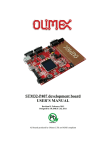
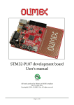
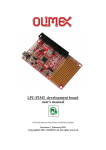
STM-P103 development board
user's manual
Rev.B, September 2013
Copyright(c) 2013, OLIMEX Ltd, Some rights reserved
INTRODUCTION:
STM32-P103 board is development board which allow exploring the complete features of
the new ARM Cortex M3 STM32F103RBT6 microcontrollers produced by ST
Microelectronics Inc.
The board have SD/MMC card connector and allow USB Mass storage device demo to be
evaluated. The RS232 driver and connector allow USB to Virtual COM port demo to be
evaluated. The CAN port and driver allow CAN applications to be developed. The UXT
connector allow access to all other UEXT modules produced by OLIMEX like MOD-MP3,
MOD-NRF24LR, MOD-NOKIA6610 etc to be connected easily. In the prototype area
customer can solder his own custom circuits and to interface them to USB, CAN, RS232 etc.
BOARD FEATURES:
-
-
CPU: STM32F103RBT6 ARM 32 bit CORTEX M3™
JTAG connector with ARM 2x10 pin layout for programming/debugging with ARMJTAG, ARM-USB-OCD, ARM-USB-TINY
USB connector
CAN driver and connector
RS232 driver and connector
UEXT connector which allow different modules to be connected (as MOD-MP3, MODNRF24LR, etc)
SD-MMC connector
backup battery connector
user button
RESET button
status LED
power supply LED
on board voltage regulator 3.3V with up to 800mA current
single power supply: takes power from USB port or extension connector pin
8 Mhz crystal oscillator
32768 Hz crystal and RTC backup battery connector
extension headers for all uC ports
RESET button
status LED
power supply LED
on board voltage regulator 3.3V with up to 800mA current
single power supply: takes power from USB port or power supply jack
PCB: FR-4, 1.5 mm (0,062"), soldermask, silkscreen component print
Dimensions: 100 x 90mm (3.94 x 3.5")
ELECTROSTATIC WARNING:
The STM32-P103 board is shipped in protective anti-static packaging. The board must not
be subject to high electrostatic potentials. General practice for working with static sensitive
devices should be applied when working with this board.
BOARD USE REQUIREMENTS:
Cables: 1.8 meter USB A-B cable to connect to USB host.
Hardware:
ARM-JTAG, ARM-USB-OCD, ARM-USB-TINY or other ARM JTAG
compatible tool
Software:
ARM C compiler and debugger software, the possible options are:
- free open source platform: GNU C compiler + OpenOCD and Eclipse
(support all low cost Olimex JTAG debuggers)
- commercial solution EW-ARM from IAR Systems AB, require
expensive J-LINK debugger
- CrossWorks from Rowley (supports all Olimex low cost JTAG
debuggers).
BOARD LAYOUT:
SCHEMATIC:
PROCESSOR FEATURES:
STM-P103 board use ARM 32-bit Cortex™-M3 CPU STM32F103RBT6 from ST
Microelectronics with these features:
- CPU clock up to 72Mhz
- FLASH 128KB
- RAM 20KB
- DMA x7 channels
- RTC
- WDT
- Timers x3+1
- SPI x2
- I2C x2
- USART x3
- USB x1
- CAN x1 (multiplexed with USB so both can't be used in same time)
- GPIO up to 51 (multiplexed with peripherials)
- 2 ADC 12-bit
- operating voltage 2.0-3.6V
- temperature -40C +85C
MEMORY MAP:
POWER SUPPLY CIRCUIT:
STM32-P103 can take power from two sources:
- USB connector where 5V power supply is applied by USB host
- PWR jack where +6-9VDC or 5-9V AC may be applied, as there is bridge rectifier the
polarity doesn’t matter
The board power consumption is: about 50 mA with all peripherials and MCU running at
full speed, there are different power saving modes which may put STM32F103RBT6 in
power sleep mode and in these modes the consumption of the MCU is only few micro
ampers.
RESET CIRCUIT:
STM32-P103 reset circuit is made with RC group R8 - 10K and C28 - 100nF.
Although on the schematic is made provision for external reset IC such is not necessary as
STM32 have build-in brown out detector. Manual reset is possible by the RESET button.
CLOCK CIRCUIT:
Quartz crystal 8Mhz is connected to STM32F103RBT6. Internal PLL circuit can multiply
this frequency up to 72Mhz.
32.768 KHz quartz crystal is connected to STM32F103RBT6 for it’s internal Real Time
Clock.
PROTOTYPE AREA CONNECTOR DESCRIPTION:
Please have look at board layout picture, all signals are on the silkscreen.
JUMPER DESCRIPTION:
R-T
Connects JTAG TRST signal to STM32F103RBT6 RESET
Default state closed (shorted)
BAT_E
Connects 3.3V to STM32F103RBT6 Vbat pin.1
Default state closed (shorten), Vbat signal is also available to BAT_3V
connector, so if you want to connect external backup battery to the
STM32F103RBT6 this jumper should be opened (unshorted) and the
external battery to be connected to BAT_3V connector(see connector
description for BAT_3V connector pining.).VBAT accept 2 - 3.6V.
USBP-E
Connects USB power supply to STM32F103RBT6 pin.24 PC4/ADC14 and
allow to detect if the board is connected to USB host.
Default state closed (shorten)
LED-E
Connects STATUS LED to STM32F103RBT6 pin.53 PC12
Default state closed (shorten)
BOOT0, BOOT1
boot sequence select
B1_H/B1_L (Boot1_High/Boot1_Low)
B0_H/B0_L (Boot0_High/Boot0_Low)
B1_H/B1_L
Default position:
Boot1 is log. 0
B0_H/B0_L
Boot0 is log. 0
CAN0_T
Connect 120 Ohm terminator between CAN_L and CAN_H
busses.
Default state closed (shorten)
CNTRL/HS
CNTRL/HS
1. CNTRL/HS jumper is open
10 KOhm resistor is connected to slope control pin of SN65HVD230 CAN
driver i.e. 15V/uS driver output signal slop.
CNTRL/HS
2. CNTRL/HS is connected to HS side
High speed of output CAN drivers (>20v/uS) – No slope control
CNTRL/HS
3. CNTRL/HS is connected to CNTRL side
Enable PC10(pin 51) of STM32F103RBT6 to control CAN driver modes.
Log. 1 of PC10 disable CAN driver. Log. 0 of PC10enable CAN driver with
high speed mode.
Default state - open
RTS_E
Connect PA1/USART2_RTS pin to COM port driver(ST3232).
USART2_RTS function of PA1 is used for handshake mode of COM port.
Default state - open
CTS_E
Connect PA0-WKUP/USART2_CTS pin to COM port
driver(ST3232). USART2_CTS function of PA1 is used for
handshake mode of COM port. By default is used Wake Up
function(PA is permanent tied to Wake Up button).
Default state – open
CP_E
Card Present Enable – Allow PC7(pin 38) to detect Multi Media
Card present in socket. Log. 1 of PC7 – MMC present. Log.0 of
PC7 – Card absent.
Default state closed (shorten)
WP_E
Write Protect Enable – Allow PC6(pin 37) to detect write
protected state of Multi Media Card. Log. 1 of PC6 – MMC no
write protected . Log.0 of PC7 – MMC is write protected.
Default state closed (shorten)
3.3V_MCU_E
Connect 3.3V regulated voltage to STM32F103RBT6
power pins. 3.3V_MCU_E jumper is used if you need to
measure current consumption of the microcontroller.
Default state closed (shorten)
INPUT/OUTPUT:
User button with name BUT – connected to STM32F103RBT6 pin.14 PA0.WKUP;
Status green LED with name STAT connected to STM32F103RBT6 pin.53 PC12, note that
LED-E SMT jumper should be shorted to may LED work properly (it’s shorted by default),
if you decide to use PC12 port for other purpose you have to remove the solder short on this
jumper which will disconnect the LED from PC12 port;
Power supply red LED with name PWR – indicates that 3.3V power supply is applied;
JTAG:
The JTAG connector allows the software debugger to talk via a JTAG (Joint Test Action
Group) port directly to the core. Instructions may be inserted and executed by the core thus
allowing STM32F103RBT6 memory to be programmed with code and executed step by
step by the host software.
For more details refer to IEEE Standard 1149.1 - 1990 Standard Test Access Port and
Boundary Scan Architecture and STM32F103RBT6 datasheets and users manual.
JTAG CONNECTOR PIN DESCRIPTIONS
Pin #
Signal Name
Pin #
Signal Name
1
TVCC 3.3V
2
TVCC 3.3V
3
TRST
4
GND
5
TDI
6
GND
7
TMS
8
GND
9
TCK
10
GND
11
NC
12
GND
13
TDO
14
GND
15
RST
16
GND
17
NC
18
GND
19
NC
20
GND
TMS
TCK
Input
Input
TDI
TDO
Input
Output
TRST
Input
Test Mode Select. The TMS pin selects the next state in the TAP state machine.
Test Clock. This allows shifting of the data in, on the TMS and TDI pins.
It is a positive edgetriggered clock with the TMS and TCK signals that define the internal state
of the device.
Test Data In. This is the serial data input for the shift register.
Test Data Output. This is the serial data output from the shift register. Data is shifted out of the
device on the negative edge of the TCK signal.
Test Reset. The TRST pin can be used to reset the test logic within the EmbeddedICE logic.
RS232:
STM32F103RBT6 have 3 USARTs which are available on the extension headers. One of
them can operate up to 4.5 Mbit/s, the other two up to 2.25 Mbit/s. They provide hardware
management of the CTS and RTS signals, IrDA SIR ENDEC support, are ISO 7816
compliant and have LIN Master/Slave capability.
All USART interfaces can be served by the DMA controller.
USART1.Tx – pin.42
PA9 EXT1-4
USART1.Rx – pin.43 PA10 EXT1-7
USART2.Tx – pin.16 PA2 EXT2-7
USART2.Rx – pin.17 PA3 EXT2-10
USART3.Tx – pin.29 PB10 EXT2-14
USART3.Rx – pin.30 PB11 EXT2-15
Pin #
Signal
Name
Pin #
Signal
Name
1
NC
6
NC
2
TxD
7
CTS
3
RxD
8
RTS
4
NC
9
NC
5
GND
SPI:
STM32F103RBT6 have 2 SPIs which able to communicate up to 18 Mbits/s in slave and
master modes in fullduplex and simplex communication modes. The 3-bit prescaler gives 8
master mode frequencies and the frame is configurable from 8-bit to 16-bit. The hardware
CRC generation/verification supports basic SD Card/MMC modes.
Both SPIs can be served by the DMA controller.
SPI1.NSS – pin.20 PA4 EXT2-11
SPI1.SCK – pin.21 PA5 EXT1-18
SPI1.MISO – pin.22 PA6 EXT1-14
SPI1.MOSI – pin.23 PA7 EXT1-22
SPI2.NSS – pin. PB12
SPI2.SCK – pin. PB13
SPI2.MISO – pin. PB14
SPI2.MOSI – pin. PB15
I2C:
STM32F103RBT6 have two I²C bus interfaces which can operate in multi-master and slave
modes. They can support
standard and fast modes. They support dual slave addressing (7-bit only) and both 7/10-bit
addressing in master
mode. A hardware CRC generation/verification is embedded.
They can be served by DMA and they support SM Bus 2.0/PM Bus.
I2C1.SDA – pin.59 PB7 EXT1-15
I2C1.SCL – pin.58 PB6 EXT1-13
I2C1.SMBA – pin.57 PB5 EXT1-12
I2C2.SDA – pin.30 PB11 EXT2-15
I2C2.SCL – pin. 29 PB10 EXT2-14
I2C2.SMBA – pin.33 PB12 EXT2-17
CAN:
The STM32F103RBT6 CAN is compliant with specifications 2.0A and B (active) with a bit
rate up to 1 Mbit/s. It can receive and transmit standard frames with 11-bit identifiers as well
as extended frames with 29-bit identifiers. It has three transmit mailboxes, two receive
FIFOs with 3 stages and 14 scalable filter banks.
The CAN and USB share same pins PA11/EXT1-1 and PA12/EXT1-3, so you can’t use both
CAN and USB on same time.
Pin # Signal Name
1
GND
2
CANL
3
CANH
USB:
The STM32F103RBT6 embeds a USB device peripheral compatible with the USB Fullspeed 12 Mbs. The USB interface implements a full speed (12 Mbit/s) function interface. It
has software configurable endpoint setting and suspend/resume support. The dedicated 48
MHz clock source is generated from the internal main PLL.
The CAN and USB share same pins PA11/EXT1-1 and PA12/EXT1-3, so you can’t use both
CAN and USB on same time.
Pin # Signal Name
1
+5V
2
USBDM
3
USBDP
4
GND
ADC:
STM32F103RBT6 have two 12-bit Analog to Digital Converters which share up to 16
external channels, performing conversions in singleshot or scan modes. In scan mode,
automatic conversion is performed on a selected group of analog inputs.
Additional logic functions embedded in the ADC interface allow:
- Simultaneous sample and hold
- Interleaved sample and hold
- Single shunt
The ADC can be served by the DMA controller.
An analog watchdog feature allows very precise monitoring of the converted voltage of one,
some or all selected channels. An interrupt is generated when the converted voltage is
outside the programmed thresholds. The events generated by the standard timers (TIMx) and
the Advanced Control timer (TIM1) can be internally connected to the ADC start trigger,
injection trigger, and DMA trigger respectively, to allow the application to synchronize A/D
conversion and timers.
MECHANICAL DIMENSIONS:
AVAILABLE DEMO SOFTWARE:
DEMO1.
Blinking LED for EW-ARM 5.11
Blinks the on-board LED.
DEMO2.
USB mouse for EW-ARM 5.11
Creates USB mouse and when board is connected to PC it starts moving
the mouse cursor in circle.
DEMO3.
Blinking LED for GCC+OpenOCD+Eclipse
Blinks the on-board LED.
ORDER CODE:
STM32-P103 – assembled and tested (no kit, no soldering required)
How to order?
You can order to us directly or by any of our distributors.
Check our web www.olimex.com for more info.
All boards produced by Olimex are ROHS compliant
Revision history:
Rev. A
- create April 2008
Rev. B
- revised September 2013
Disclaimer:
© 2013 Olimex Ltd. All rights reserved. Olimex®, logo and combinations thereof, are registered trademarks of
Olimex Ltd. Other terms and product names may be trademarks of others.
The information in this document is provided in connection with Olimex products. No license, express or implied
or otherwise, to any intellectual property right is granted by this document or in connection with the sale of Olimex
products.
Neither the whole nor any part of the information contained in or the product described in this document may be
adapted or reproduced in any material from except with the prior written permission of the copyright holder.
The product described in this document is subject to continuous development and improvements. All particulars of
the product and its use contained in this document are given by OLIMEX in good faith. However all warranties
implied or expressed including but not limited to implied warranties of merchantability or fitness for purpose are
excluded.
This document is intended only to assist the reader in the use of the product. OLIMEX Ltd. shall not be liable for
any loss or damage arising from the use of any information in this document or any error or omission in such
information or any incorrect use of the product.