1
<<< User’s Manual >>>
1. Input
Voltage:
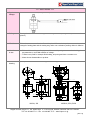
Put a wire to a coil terminal, and put electric power.
2. Setting
Turning the outlet side of valve up, and installing it vertically for ground. (Refer to an above
picture.)
3. Vibration
This valve causes some vibration. To avoid any bad effect to device, to have an attention to the
strength of setting plate and the setting way, and to use a vibration-proofing rubber is effective.
4. Attention
to use
○ This model is not drip-proof equipment. Please avoid pouring water over. Particularly, please
pay attention to use at ON condition of voltage.
○ If there is any fault for example fluid leaking, stop using and have a contact to us.
○ Please do not disassemble our product.
5. Outline
drawing
※It is possible to choose from some types for water application.
44
19
(2 3)
15
13
29. 3
OUT
18 7 F ast on tab
R1 /8
O UT
18
9
12
1 1
18.7
8
R1/8
12
26
MV201, 202
9
R 1/8
IN
14 .9
15
8
R1/8
66
33. 1
62
28.3
φ30
12
IN
MV5010, 5020, 5028
Nippon Control Kogyo Co., Ltd. Sales Dept. 5-1-16 Chiyoda, Sakado, Saitama 350-0214 JAPAN.
Tel. +81-49-283-7711 – Fax. +81-49-283-7717 – www.nipcon.co.jp
[Ver.1.0]