1
Probe Bandwidth Calculations
Technical Brief
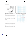
Figure 1. Discrete
Model of Probe Loading.
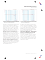
Figure 2. Distributed
Model of Probe Loading.
Historically, oscilloscope probes have been described
using discrete models. A typical discrete model, as
shown in Figure 1, describes the probe loading as DC
resistance and an input capacitance.
on the physical properties of the material around the
transmission line. For a microstrip transmission line on
FR-4 circuit board material, the propagation velocity is
about 150 ps/inch, which is about half the speed of
light. For a signal rise time of 500 ps, the length of
transmission line over which the rise time variation of
the signal can be observed is about three inches
(electrical length = signal rise time/propagation
velocity). A conservative guideline that can be applied
is that an interconnect can be expected to show
transmission line effects for interconnects longer
than 1/6th the length over which the signal variation
propagates (0.5 inch for the microstrip transmission
line example)*1. As long as the physical characteristics
of the circuit are smaller than this 1/6th of a propagation
length, a discrete model can be used. However as
electrical interconnects get faster, this becomes much
more of an issue. A 100 ps rise time signal will have
a 0.66 inch propagation length in FR-4. Features
larger than 0.11 inches will start to show transmission
line effects.
This is a valid method when the signal speeds are
slow. Electrical signals will propagate down a transmission line with a propagation velocity that depends
Oscilloscope probes are now being described with
distributed models, as shown in Figure 2. These models
help to take into account transmission line effects.
Increasing signal speed for digital communications
has placed new demands on probe electrical performance and loading. High speed signal probing requires
an oscilloscope probe to measure signals in a transmission line environment. The effect of probe loading
in a transmission line environment requires a more
complex treatment than the simple discrete probe
load models once commonly used. Probe loading
effects in a distributed circuit environment have also
led a probe vendor to introduce a new approach to
both probe measurement and probe specification.
Because this new approach has created some
confusion in the probe market, this paper will examine
this new approach and compare it with the more
traditional, accepted approach.
Probe Loading
*1"TekConnect™ Probes: Signal Fidelity Issues and Modeling", Tektronix, Inc.
2
www.tektronix.com/accessories