1
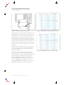
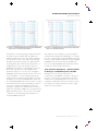
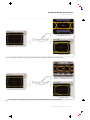
Probe Bandwidth Calculations
Technical Brief
Agilent takes the position that the loading of the probe
has an impact on the measured signal such that
VSOURCE ≠ VIN. They assert that the probe’s frequency
dependent loading has to be measured and factored
into the calibration to accurately derive the bandwidth
of the probe. A probe that has been characterized
with this method gives a bandwidth and probe
response that includes the loading of the probe in a
50Ω environment. This probe does not attempt to
compensate for the loading, but in fact includes
the loading. An Agilent probe displays on the
oscilloscope screen the original signal as it has
been loaded by the probe.
If a probe existed that had no loading, both philosophies
would converge and you would see no difference
between the probes. Since probe loading does exist,
the difference in measurement philosophy has an
impact on both the waveform displayed by the probe
and the specifications of the probe bandwidth.
To better explain the difference in philosophies, let
us look at a simplified example. Suppose you have a
perfect 1VDC signal that you want to measure. When
you measure this signal with a probe, you expect the
probe to measure 1VDC. If probe loading caused the
signal level to drop to 0.95V, would you want the
probe to read 1VDC or 0.95VDC? The Tektronix
philosophy is that you want to see a 1V signal.
Agilent’s philosophy is that you want to see the
0.95V signal.
This example can be taken one step further. Suppose
you want to measure a perfect AC sinusoidal 1Vpp
signal. This signal can be swept from a few hertz to
gigahertz frequencies and still have a perfect 1Vpp
signal level. As the signal source is swept through its
frequency range, should the probe output change with
frequency due to its changing load profile or should
the output of the probe read 1Vpp throughout the
4
www.tektronix.com/accessories
majority of its frequency range? This is a simplified
example, but it clearly illustrates the differences in
probing philosophy.
Tektronix believes that it is more useful for probe
users to know what is happening inside their circuits
when the probe is not attached. The remainder of this
paper examines in greater detail the effect of Agilent’s
probing philosophy and why Tektronix supports the
traditional bandwidth measurement technique.
How Probe Bandwidth is Measured
Tektronix designs the probe response to be as flat as
possible throughout its frequency range. This flatness
is tested with a Network Analyzer that has been
calibrated along with a probe test fixture to be a flat
source out to 20 GHz, as shown in Figures 4 and 5.
Network analyzers typically have special high
frequency coaxial connectors, so a special probe
calibration test fixture is used to connect the probe to
the network analyzer. The network analyzer is then
calibrated to take out any frequency effects of the
cables and the test fixture. This method insures the
repeatability of the measurement because there can
be slight differences in cables and fixtures between
test stations. This flat system is what Tektronix defines
as VSOURCE or VIN.
The probe is then connected to the test fixture, as
shown in Figure 6, and the response of the probe is
measured, as shown in Figure 7.
Probes have components that can be used to adjust
their frequency response. These components can be
actively adjusted to calibrate the probe in real time
and make the response as flat as possible throughout
its frequency range. One advantage of this method is
that the frequency dependant loading of the probe is
automatically compensated in the process.