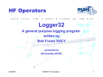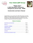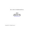
1
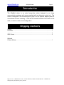
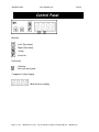
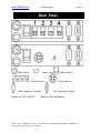
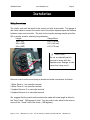
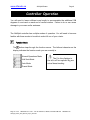
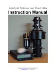
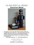
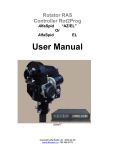
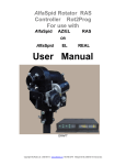
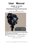
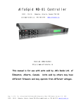
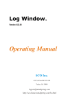
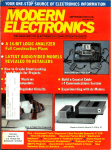
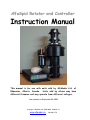
AlfaSpid Rotator and Controller
Instruction Manual
This manual is for use with units sold by AlfaRadio Ltd. of
Edmonton, Alberta, Canada. Units sold by others may have
different firmware and may operate from different voltages.
Last updated on September 08 2008
Copyright AlfaRadio Ltd 2002-2008 2008-01-15
www.alfaradio.ca
780.466.5779
AlfaSpid Rotator
www.alfaspid.com
Page 2
Table of Contents
Introduction ............................................................................................ 4
Shipping Contents.................................................................................. 4
Technical Data ....................................................................................... 4
Control Panel ......................................................................................... 5
Rear Panel ............................................................................................. 6
Installation .............................................................................................. 7
Bench Testing..................................................................................... 8
Resetting the Controller ......................................................................... 9
Controller Operation............................................................................. 10
Function Mode.................................................................................. 10
Normal Operations Mode ................................................................. 11
Half Auto Mode................................................................................. 11
Auto Mode ........................................................................................ 11
Preset Mode ..................................................................................... 11
Setup Mode ...................................................................................... 12
Programable High Limit .................................................................... 12
Programmable Low Limit.................................................................. 13
Programmable Reset Value ............................................................. 13
Preset 1 - 6 ....................................................................................... 13
Mouse Controller.................................................................................. 15
Using the AlfaSpid Rotator with LONG Cable Distances ..................... 18
Warranty .............................................................................................. 21
Notes.................................................................................................... 22
This manual is for use with units sold by AlfaRadio Ltd. of
Edmonton, Alberta, Canada. Units sold by others may have
different firmware and may operate from different voltages.
Last updated on September 15, 2008
Page 2 of 23
Alfa Radio Ltd. 11211 - 154 St. Edmonton, Alberta, Canada T5M 1X8
780 466 5779
www.alfaradio.ca
AlfaSpid Rotator
Page 3
Introduction
The AlfaSpid rotator is an extra heavy-duty rotator designed to run large
communication antennas and comes complete with an electronic control unit. The
rotator is designed to be mounted pipe to pipe or on an optional adaptor plate for
conventional in tower mounting. It can also be mounted outside of the tower on the
mast, or used in a side mount configuration.
Shipping Contents
Rotator ..................................................................................................................1
Controller...............................................................................................................1
..............................................................................................................................1
GMA Fuses ...........................................................................................................2
Optional
Custom Mouse ......................................................................................................1
Page 3 of 23
Alfa Radio Ltd. 11211 - 154 St. Edmonton, Alberta, Canada T5M 1X8
AlfaSpid_Rotator_RAK_Manual_Sept15_2008.doc
780 466 5779
AlfaSpid Rotator
www.alfaspid.com
Page 4
Front Panel
Control
Panel
Buttons
-Left (Decrease)
-Right (Increase)
-Setup
-Function
Indicators
-Overlap
-Not currently used
7 segment 4-digit display
- Multifunction display
Page 4 of 23
Alfa Radio Ltd. 11211 - 154 St. Edmonton, Alberta, Canada T5M 1X8
780 466 5779
www.alfaradio.ca
AlfaSpid Rotator
Page 5
Rear Panel
-Fuse Holder
- Power Cord
- Terminal Strip
-DB-9 connector (female)
Female for CPU / RS232
Page 5 of 23
- Power Switch
4 Pin Connector
-DB-9 connector (male)
Male for AlfaSpid Mouse
Alfa Radio Ltd. 11211 - 154 St. Edmonton, Alberta, Canada T5M 1X8
AlfaSpid_Rotator_RAK_Manual_Sept15_2008.doc
780 466 5779
AlfaSpid Rotator
www.alfaspid.com
Page 6
Installation
Wiring Connections
The rotator unit must be wired to the control unit with 4-wire cable. The gauge of
the 4-wire cable to connect the control unit to the rotator depends upon the distance
between rotator and controller. The wire for the impulse sensing may be quite thin #22 or similar, even for relatively long distances.
Length
Gauge Motor
10 m (32')
#18 (1.19 mm)
30 m (100')
#16 (1.42 mm)
60 m (200')
#14 (1.75 mm)
CAUTION!:
Do not accidentally switch
the motor wires with the
impulse wires. Damage to the
control unit may occur!
Remove cover from the motor body as shown and make connections as follows:
1 Motor Drive to 1 on controller terminal
2 Motor Drive to 2 on controller terminal
3 Impulse Sense to 3 on controller terminal
4 Impulse Sense to 4 on controller terminal
We suggest that the coax from the antenna be made with extra length to allow for
the “Over Travel” 720 degrees in total. You may wish to also allow for the coax to
come off the “South” side of the tower ( 180 degrees ).
Page 6 of 23
Alfa Radio Ltd. 11211 - 154 St. Edmonton, Alberta, Canada T5M 1X8
780 466 5779
www.alfaradio.ca
AlfaSpid Rotator
Page 7
Bench Testing of Control Box
The control box is normally expected to be operated from a 12 Volt DC supply;
however it may be operated from other unregulated DC or AC sources as well. DC
or AC voltage levels between 10 and 26 Volts capable of at least 5 Amps are
acceptable, typically 12 or 14 Volts.
The polarity of the power to the control box input leads is not critical for D.C.
operation; a diode rectifier on the input will provide the proper polarity to the
electronics and provide reverse polarity protection as well as A.C. operation.
TIP: Because of several steering diodes in the motor path, the voltage delivered
to the motor (neglecting wire loss) will be about 1.4 volts less than the power supply
voltage. For longer runs and/or thin wiring a higher voltage (up to approx 24V) to
the control unit is beneficial. A simple way to estimate if the voltage to the motor is
adequate is by timing the rotation. Under no or a very small load, the 360 degree
rotation time with 12V DC at the motor is about 120 second (2 minutes). With 24 V
DC is about 60 second (1 minute). A DC Ammeter in the motor lead is also useful,
it should indicate between 1 and 3 amps with a small load. On windy days or heavy
load, the current may fluctuate up to 3 to 5 amps.
Notes – testing and troubleshooting
It is highly recommended to ground the Control Box.
should make the rotator move clockwise. Pressing
should make the
Pressing
rotator move counter-clockwise. If rotation is reversed, switch lines 1 and 2 on the
back of the controller.
Impulse sense lines (3 & 4) have no polarity concerns.
Part of the protection circuitry involves removing motor power if the controller
receives no sense indication. If the motor turns for a few seconds and then you
hear the relay in the control box drop out, the motor has either stalled or there is a
problem in the impulse sense wiring.
Page 7 of 23
Alfa Radio Ltd. 11211 - 154 St. Edmonton, Alberta, Canada T5M 1X8
AlfaSpid_Rotator_RAK_Manual_Sept15_2008.doc
780 466 5779
AlfaSpid Rotator
www.alfaspid.com
Page 8
Resetting the Controller
Since there are no mechanical limits in the rotator, it may be installed with the
antenna pointing in any direction. There is no reason to locate “TRUE NORTH”
until you are ready to calibrate the control box. Use the controller to position the
antenna to physically point north, then reset the controller as follows:
Turn the unit OFF. Then while holding the
button depressed turn control unit
on the display. The controller is now set for
back on. This will now show
North.
Display adjustment:
Press the
button to cycle thru to the normal (i.e. blank) setting until you see the
display after P5 X, (X is the mode for computer interface) It will be blinking. The
display shows the normal degree reading i.e. 30 degrees, with the left or right
arrows the display reading can be changed with out turning the rotator in this mode,
this feature can be used if, for any reason, the direction of the antenna becomes
incorrect. This may be caused by antenna to mast slippage or incorrect initial
alignment. The Rotator to mast will not slip unless there is improper installation.
See Heading Adjust (numbers blinking) else where in this document.
IMPORTANT:
The AlfaSpid rotator is now set at the counter-clockwise end of its normal rotation
range. Normal rotation range is in a clockwise direction for 360 degrees.
From the reset position, you can rotate counter-clockwise an additional 180 degrees
in over-travel, as well 360 degrees clockwise, plus an additional 180 degrees into
clockwise over-travel.
Counter-clockwise over-travel is indicated by a steady dot above the over-travel
Rotation past 359 degrees into the clockwise over-travel is indicated by a
icon.
blinking dot above the over-travel icon.
Technical Note:
Page 8 of 23
Alfa Radio Ltd. 11211 - 154 St. Edmonton, Alberta, Canada T5M 1X8
780 466 5779
www.alfaradio.ca
AlfaSpid Rotator
Page 9
Controller Operation
You will need to leave sufficient coax length to accommodate the additional 180
degrees of over-travel on each end of normal rotation. Failure to do so can cause
damage to your coax and/or antennas.
The AlfaSpid controller has multiple modes of operation. You will need to become
familiar with these modes to be able to make full use of your rotator.
Function Mode
The
button steps through the function menus. The leftmost character on the
display indicates the function mode you are currently in.
- Normal Operations Mode
- Half Auto Mode
- Auto Mode
The 0 in the displays to
the left will be replaced by your
actual beam heading
- Preset Mode
Page 9 of 23
Alfa Radio Ltd. 11211 - 154 St. Edmonton, Alberta, Canada T5M 1X8
AlfaSpid_Rotator_RAK_Manual_Sept15_2008.doc
780 466 5779
AlfaSpid Rotator
www.alfaspid.com
Page 10
- Normal Operations Mode
In Normal Operations Mode, the
buttons are pressed. Pressing
to setup mode.
and
buttons cause rotation as long as the
while in normal operations mode will take you
- Half Auto Mode
In Half Auto Mode, the
and
buttons can be used to pre-select the desired
beam heading. The heading displayed on the controller will rapidly change in
the direction of desired rotation. Once the desired beam heading is shown on
the display, release the key. Approximately ½ of a second after no key presses
have been detected, the display will revert back to the actual beam heading, and
rotation towards the desired heading will take place. Pressing any key while in
transit to the desired heading will cancel the action.
- Auto Mode
In Auto Mode, the controller will respond to commands from control software
running on an attached computer. The
manual override.
and
buttons can still be used as a
- Preset Mode (requires optional mouse)
In Preset Mode, the
and
buttons cause rotation as long as the buttons are
pressed. With the optional mouse attached, the six preset buttons can be used
to select a desired beam heading. Preset beam heading values are set in Setup
Mode
Page 10 of 23
Alfa Radio Ltd. 11211 - 154 St. Edmonton, Alberta, Canada T5M 1X8
780 466 5779
www.alfaradio.ca
AlfaSpid Rotator
Page 11
Setup Mode
button steps through the setup menu. The display cycles through each
The
of the setup menu items.
1.00
or
0.50 ratio setting ( Default is 1.00 )
- Programmable High Limit Default flashing “DOT” 180
- Programmable Low Limit Default not flashing “DOT” 180
- Programmable Reset Value
0 or 180
- Preset 1
- Preset 2
- Preset 3
- Preset 4
- Preset 5
- Preset 6
- Program Simulation
- Heading Adjust (numbers blinking)
- Programmable High Limit
The Programmable High Limit is a user adjustable clockwise travel limit value.
By reducing this value, the maximum clockwise rotation travel can be restricted.
Use the
and
buttons adjust the value.
These limits can be used when side mounting the rotor to keep
the antenna from colliding with the tower.
Page 11 of 23
Alfa Radio Ltd. 11211 - 154 St. Edmonton, Alberta, Canada T5M 1X8
AlfaSpid_Rotator_RAK_Manual_Sept15_2008.doc
780 466 5779
AlfaSpid Rotator
www.alfaspid.com
Page 12
- Programmable Low Limit
The Programmable Low Limit is a user adjustable counter-clockwise travel limit
value. By increasing this value, the minimum counter-clockwise rotation travel
can be restricted. Use the
and
buttons adjust the value.
- Programmable Reset Value
The Programmable Reset Value can be set to either 0 degrees, or 180 degrees.
This is the beam heading set when a power on reset event is triggered. If you
wish to reset your rotator to south, set this value to 180.
- Preset 1
P1 Thru P6
- Preset 6
These 6 presets are user adjustable values that map to the 6 preset buttons on
the optional mouse controller. You can set each preset to a commonly used
beam heading, allowing rapid single button heading selections.
Page 12 of 23
Alfa Radio Ltd. 11211 - 154 St. Edmonton, Alberta, Canada T5M 1X8
780 466 5779
www.alfaradio.ca
AlfaSpid Rotator
Page 13
- Program Simulation
Program Simulation allows the user to set the serial communication protocol
used by the rotator. When set to emulate another brand of rotator, the AlfaSpid
will respond to commands, and send responses back to the computer as if it
were the rotator brand selected. If your favourite software supports a rotator,
chances are, the AlfaSpid will be able to interface to your software. There are 4
modes available: Note: some programs may not support the 1200 Baud
requirements of the controller in emulation mode.
- Spid ( AlfaSpid ) Recommended
- Orion
- Hygain
- Yaesu
- Heading Adjust (numbers blinking)
This setting can be used to make minor heading adjustments without causing
the rotator to turn. If you notice that the heading displayed on the controller to a
known signal source is out by a few degrees, you can change the heading
displayed on the LED readout to match the known heading, rather than having to
turn back to North and reset the controller.
Page 13 of 23
Alfa Radio Ltd. 11211 - 154 St. Edmonton, Alberta, Canada T5M 1X8
AlfaSpid_Rotator_RAK_Manual_Sept15_2008.doc
780 466 5779
AlfaSpid Rotator
www.alfaspid.com
Page 14
Mouse Controller (Optional)
The optional mouse controller allows easy desktop access to the most commonly
used front panel controls. These buttons are functionally equivalent to the
corresponding front panel controls.
- Left (Decrease)
- Right (Increase)
- Stop ( also the wheel between left and
right buttons )
The mouse controller is a
highly modified computer
mouse. You can not use a regular
mouse with the AlfaSpid
In addition to the above controls, you will find 6 programmable preset buttons on the
mouse. Programmable preset buttons are only available via the optional mouse
controller. Preset headings are programmed via the Setup Mode
The mouse ball serves no function; the mouse simply provides an ergonomically
pleasing case in which to mount the controls.
Page 14 of 23
Alfa Radio Ltd. 11211 - 154 St. Edmonton, Alberta, Canada T5M 1X8
780 466 5779
www.alfaradio.ca
AlfaSpid Rotator
Page 15
Alfa Radio Ltd. Trouble shooting tips
Before contacting AlfaRadio Ltd. Please make the following tests:.
The following are some trouble shouting tips, if for some reason your AlfaSpid will
not operate correctly.
It is important to confirm correct operation before installing on the tower. This will
rule out any damage that may have been caused by the shipping company.
Check the Limits - PH and PL settings and rule out overlap.
Simple resistance tests can reveal incorrect or shorted wiring.
Pins 1 and 2 are the motor winding and will have a low resistance. Typical 2 - 3
ohms.
Pins 3 and 4 are the sense lines and typically will have either an open circuit or
have about 1200 ohms depending on the status of the reed switch in the rotator and
the length and gauge of used wire.
There should be no conductivity between 1 and 3 or 1 and 4, or between 2 and 3 or
2 and 4
All lines should have no conductivity to ground.
Page 15 of 23
Alfa Radio Ltd. 11211 - 154 St. Edmonton, Alberta, Canada T5M 1X8
AlfaSpid_Rotator_RAK_Manual_Sept15_2008.doc
780 466 5779
AlfaSpid Rotator
www.alfaspid.com
Page 16
Be careful not to over wind your coax with the next test, as there will be no
protection from over turning.
Find a small 12 volts supply which will deliver 3 to 4 amps. ( a small 12 Volt battery
will work just fine )
To confirm that the motor runs you may connect 12 volts D.C. to the lines that go to
the motor, pins 1 and 2, it should turn. Reversing the 12 Volts D.C. should cause
the motor to turn in the reverse direction.
To confirm that the sense circuit in the rotator is working, connect an ohm meter to
the senses lines pins 3 and 4, apply 12 volts to the motor lines pins 1 and 2; you
should see the ohm meter reading alternate between open circuit and about 1200
ohms.
Pin on Rotator not
controller
Typical Reading
Your
reading
Pins 1 to 2
About 2 to 4 Ohms
________
Pins 3 to 4
Pins 1 to 3
Pins 2 to 3
Pins 2 to 4
Open or 1200 Ohms
Open
Open
Open
Pin 1 to Ground
Pin 2 to Ground
Pin 3 to Ground
Pin 4 to Ground
Open
Open
Open
Open
________
________
________
________
________
________
________
________
________
________
Depends on the length of
wire to rotator
Depends on the status of
the read switch
Voltage on controller
Pins 1 to 2
Pins 3 to 4
About 12 volts with motor running
About 8.5 volts or 2.5
volts *
Depends on the supply
voltage (14 volt applied)
Depends on the status of
the read switch
and the Supply voltage
Page 16 of 23
Alfa Radio Ltd. 11211 - 154 St. Edmonton, Alberta, Canada T5M 1X8
780 466 5779
www.alfaradio.ca
AlfaSpid Rotator
Page 17
Using the AlfaSpid Rotator with LONG Cable Distances
By VE6JY
Since the motor uses relatively low voltage DC, a combination of long cable
runs and/or thinner than required cable may reduce the voltage at the motor to an
unacceptably low value. It may turn in warm weather or light winds but the power
will not be available to rotate under more severe conditions.
While it is easy to say just use a heavier cable, this may be costly,
impractical or both. I have one tower that is over 1700 feet (approx 500 meters
away) and running large cable out there would be very expensive.
My solution is to use this rotator controller's output voltage to control another
set of relays that will feed a higher voltage DC to the motor. In the abovementioned example, I find a voltage between 60 to 80 volts gave suitable
performance. This is a pretty extreme case but it illustrates the versatility of this
design. The external DC supply voltage needed will vary depending on the DC
voltage rating of your motor, the cable size and length of the run. Typically 36 to 50
volts at 3-5 amps should be quite adequate. These DC motors are quite tolerant on
their voltage ratings.
Page 17 of 23
Alfa Radio Ltd. 11211 - 154 St. Edmonton, Alberta, Canada T5M 1X8
AlfaSpid_Rotator_RAK_Manual_Sept15_2008.doc
780 466 5779
AlfaSpid Rotator
www.alfaspid.com
Page 18
Relay Board Schematic
Page 18 of 23
Alfa Radio Ltd. 11211 - 154 St. Edmonton, Alberta, Canada T5M 1X8
780 466 5779
www.alfaradio.ca
AlfaSpid Rotator
Page 19
Relays chosen should be suitable for the proper coil voltage as well as appropriate
current carrying capability. A relay capable of 5 to 10 amps DC is adequate. The
diode in series with Relay K1 is any general purpose 1 amp style such as the
1N400x series. If the motor rotates incorrectly, simply reverse the leads to the
motor or from the External DC Supply.
The controller also has the capability to, with a small modification, allow you
to input your external DC voltage into the unit and use the internal relays to control
the rotator as usual.
This information is presented as a guide to help the user realize a solution to
the long cable run situation.
If you do not feel comfortable wiring basic circuitry to do this, please contact
Alfa Radio Ltd. (www.alfaradio.ca) for a pre-wired solution.
Prepared for Alfa Radio Ltd by VE6JY Don Moman Dec 6/2001
Page 19 of 23
Alfa Radio Ltd. 11211 - 154 St. Edmonton, Alberta, Canada T5M 1X8
AlfaSpid_Rotator_RAK_Manual_Sept15_2008.doc
780 466 5779
AlfaSpid Rotator
www.alfaspid.com
Page 20
12 MONTH LIMITED WARRANTY
AlfaSpid Rotator and controller
Alfa Radio Ltd. Warrants to the user, who originally purchased the product, that the
product will be free from defects in material and workmanship for the following periods
after such date of purchase: Material, 12 months : Workmanship, 12 months.
Alfa Radio Ltd. will, at its option, repair or replace free of charge such defective
products subject to the following conditions:
1. Delivery of the product prepaid to Alfa Radio Ltd. or its authorized dealer.
2. Determination by the Alfa Radio Ltd. that a defect exists and is covered by the
limited warranty. Defects due to alteration, pinning the mast to the rotator, repair
by an unauthorized person, misuse, accidental damage, lightning strikes, use of
the equipment for purpose other than those for which it was designed, and the
like, are NOT COVERED by this limited warranty. Repairs therefore will be
subject to normal service charges.
3. Repairs and replacement parts are covered under this limited warranty only for
the remaining term of the original limited warranty.
4. Under no circumstances is Alfa Radio Ltd. liable for consequential damages to
person(s) or property by the use of this product.
5. Alfa Radio Ltd. reserves the right to make changes or improvements in design or
manufacture or firmware without incurring any obligations to install such
changes upon any of the product previously manufactured.
All claims of defect or shortage should be sent prepaid to:
Alfa Radio Ltd.
11211 - 154 Street
Edmonton, Alberta
T5M 1X8
CANADA
All shipments must be accompanied by the letter describing the problem in detail along
with a copy of your proof-of-purchase.
Contact AlfaRadio for authorization be for shipping.
www.alfaradio.ca
780 446 8958
WE SERVICE WHAT WE SELL
Page 20 of 23
Alfa Radio Ltd. 11211 - 154 St. Edmonton, Alberta, Canada T5M 1X8
780 466 5779
www.alfaradio.ca
AlfaSpid Rotator
Page 21
NOTES:
________________________________________________________________
________________________________________________________________
________________________________________________________________
________________________________________________________________
________________________________________________________________
________________________________________________________________
________________________________________________________________
________________________________________________________________
________________________________________________________________
________________________________________________________________
________________________________________________________________
________________________________________________________________
________________________________________________________________
________________________________________________________________
________________________________________________________________
Page 21 of 23
Alfa Radio Ltd. 11211 - 154 St. Edmonton, Alberta, Canada T5M 1X8
AlfaSpid_Rotator_RAK_Manual_Sept15_2008.doc
780 466 5779
AlfaSpid Rotator
www.alfaspid.com
Page 22
Typical travel of the AlfaSpid Rotator
Blue 0 to 180 is the dot (not flashing) PH over travel (Right 180 side of diagram)
Red 0 to 180 is the dot(flashing) PL over travel ( Left 180 side of diagram)
Page 22 of 23
Alfa Radio Ltd. 11211 - 154 St. Edmonton, Alberta, Canada T5M 1X8
780 466 5779
www.alfaradio.ca
AlfaSpid Rotator
Page 23
Technical Data
Input Voltage (Typical) .......................................................................... 13.8 – 24 Volts DC
Input Current (Nominal Draw) at 12 Volts with no or small load ....................... 3 – 4 Amps
Motor........................................................................................................ 12 – 24 Volts DC
Fuse ..............................................................................................................8.0 Amp GMA
Specifications: AlfaSpid RAK
Azimuth Rotator
Turning torque in lbs / N m
Brake torque in lbs / N m
Brake Construction
Vertical Load lbs / Kg
Rotation Speed (360 Deg)
Precision
Rotation Range
Weight lbs / Mass Kg
Position Sensor
Mast size top / bottom – in / mm
Specifications: AlfaSpid BIG RAK
Turning torque in lbs / N m
Brake Torque in lbs / N m
Brake Construction
Vertical Load lbs / Kg
Rotation Speed (360 Deg)
Precision
Rotation Range
Weight lbs / Mass Kg
Position Sensor
Mast size top / bottom – in / mm
Specifications: AlfaSpid controllers
Computer interface
Pre sets with Mouse
Emulation
Limit settings
User settable calibration
Precision
Rotation Range
Weight lbs / Mass Kg
Connections to Rotator
RAK @ 12V
1,400 in lb / 158 N m
14,000 in lb / 1,582 N m
Double Worm Gears
550 lbs / 250 Kg
120 sec
1 deg
720 deg
16 lbs / 7 Kg
Reed Switch
2.0 / 2.6 in, 50 / 66 mm
BIG RAK @ 12V
>5,000 in lb / 565 N m
24,000 in lb / 2,712 N m
Double Worm Gears
>700 lbs / 318 Kg
120 sec
1 / 0.5 deg
720 deg
24 lbs / 11 kg
Reed Switch
2.6 / 2.6 in, 66 / 66 mm
When used with RAK or REAL
13.8 – 24 V AC or DC
RS 232 1200 baud 8 N 1
6 User settable presets
Spid, Hygain, Orion, Yaesu
2 – AZ
CW point & CCW point
N or S or any degree
1 / 0.5 deg
720 deg
2.75 lbs / 1.2 Kg
4 wires ( 2 sens, 2 motor )
RAK @ 24V
3,240 in lb / 366 N m
14,000 in lb / 1,582 N m
Double Worm Gears
550 lbs / 250 Kg
60 sec
1 deg
720 deg
16 lbs / 7 Kg
Reed Switch
2.0 / 2.6 in, 50 / 66 mm
BIG RAK @ 24V
Contact AlfaRadio
24,000 in lb / 2,712 N m
Double Worm Gears
>700 lbs / 318 Kg
60 sec
1 / 0.5 deg
720 deg
24 lbs / 11 kg
Reed Switch
2.6 / 2.6 in, 66 / 66 mm
When used with RAS or REAL
13.8 – 24 V AC or DC
RS 232 600 baud 8 N 1
N/A
Spid, Yaesu
4 ( 2 AZ - 2 EL )
AZ & EL, any degree
1 , 0.5, 0.25 deg
360 / 180 - 180 deg
4.75 lbs / 2.1 Kg
4 wires ( 2 sens, 2 motor ) EL
4 wires ( 2 sens, 2 motor ) AZ
Total 8 wires RAS, 4 wires for REAL
All specifications may change with out further notice and all values are approx.
Page 23 of 23
Alfa Radio Ltd. 11211 - 154 St. Edmonton, Alberta, Canada T5M 1X8
AlfaSpid_Rotator_RAK_Manual_Sept15_2008.doc
780 466 5779