1
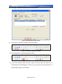
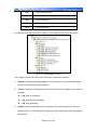
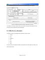
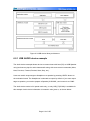
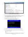
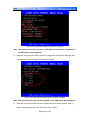
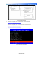
to EEPROM_WriteAddress2, which represents the address just after the last written one in the first write. After completion of the second write operation, the written data are read. The contents of the written and the read buffers are compared. All transfers are managed in DMA mode (except when 1-byte read/write operation is required). Once sEE_ReadBuffer() or sEE_WriteBuffer() function is called, the user application may perform other tasks in parallel while Read/Write operation is managed by DMA. This example provides the option to use the DevKit1207 LCD screen for messages display (transfer status: Ongoing, PASSED, FAILED).To enable this option, user need to uncomment the define ENABLE_LCD_MSG_DISPLAY in the main.c file. 4.18.2 GSensor-LIS33DE 1) Purpose This example shows how to configure the MEMS accelerometer to detect acceleration on X/Y/Z axes. Note: Make sure that jumpers JP7 and JP8 are fitted. Connect a null-modem female/female RS232 cable between the DB9 connector COM1 (USART3) and PC serial port if you want to display data on the Hyper Terminal. Hyperterminal configuration:Word Length = 8 Bits, One Stop Bit, No parity, BaudRate= 115200 baud,flow control: None 2) Description After startup, the program checks for the G-Sensor (MEMS accelerometer) status registers and behaves as follows: If the board is moved as shown below, the acceleration is detected on the X/Y/Z axis. Page 87 of 155