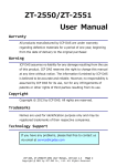
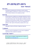
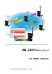
1
ZT-USB Series User Manual Warranty All products manufactured by ICP DAS are under warranty regarding defective materials for a period of one year, beginning from the date of delivery to the original purchaser. Warning ICP DAS assumes no liability for any damage resulting from the use of this product. ICP DAS reserves the right to change this manual at any time without notice. The information furnished by ICP DAS is believed to be accurate and reliable. However, no responsibility is assumed by ICP DAS for its use, nor for any infringements of patents or other rights of third parties resulting from its use. Copyright Copyright © 2013 by ICP DAS. All rights are reserved. Trademarks Names are used for identification purpose only and may be registered trademarks of their respective companies. Technology Support If you have any problems, please feel free to contact us via email at [email protected] ICP DAS, ZT‐USB Series User Manual, Version 1.0 Page 1 Copyright @ 2013 by ICP DAS Co., Ltd. All Rights Reserved. Table of Contents 1 Introduction to ZigBee ............................... 4 2 Introduction to the ZT‐USB Series .................... 5 3 Hardware Information ................................. 6 3.1 3.2 3.3 3.4 Specifications ........................................ 6 ZT‐USB Series Front View .............................. 7 Dimensions (Units: mm) ................................ 8 Block Diagram ......................................... 9 4 Installing Driver and Utility ....................... 10 4.1 4.2 4.3 Installing the ZT‐USB Serial Port Driver ............. 10 Inserting the ZT‐USB and installing Driver ........... 13 Installing the Configuration Tool .................... 17 5 Setting up the ZT‐USB Series ........................ 19 5.1 5.2 5.3 Introduction of configurations ....................... 19 Configuring ZigBee Setting ........................... 23 Test Communications .................................. 26 5 Applications ........................................ 27 6 Troubleshooting ..................................... 28 6.1 6.2 Technical Support .................................... 28 LED Indicator Status ................................. 29 ICP DAS, ZT‐USB Series User Manual, Version 1.0 Page 2 Copyright @ 2013 by ICP DAS Co., Ltd. All Rights Reserved. What’s in the shipping package? The shipping package includes the following items: ZT‐USB Series Quick Start CD If any of these items are missing or damaged, please contact your local distributor for more information. Save the shipping materials and cartons in case you want to ship the module in the future. More Information Documentation: CD: \Napdos\ZigBee\ZT_Series\document http://ftp.icpdas.com/pub/cd/usbcd/napdos/zigbee/zt_series/document Software: CD: \Napdos\ZigBee\ZT_Series\utility http://ftp.icpdas.com/pub/cd/usbcd/napdos/zigbee/zt_series/utility Driver: CD: \Napdos\ZigBee\ZT_Series\driver http://ftp.icpdas.com/pub/cd/usbcd/napdos/zigbee/zt_series/driver ICP DAS, ZT‐USB Series User Manual, Version 1.0 Page 3 Copyright @ 2013 by ICP DAS Co., Ltd. All Rights Reserved. 1 Introduction to ZigBee ZigBee is a specification for a suite of high-level communication protocols using small, low-power digital radios based on the IEEE 802.15.4 standard for personal area networks. ZigBee devices are often used in mesh network form to transmit data over longer distances, passing data through intermediate devices to reach more distant ones. This allows ZigBee networks to be formed ad-hoc, with no centralized control or high-power transmitter/receiver able to reach all of the devices. Any ZigBee device can be tasked with running the network. ZigBee is targeted at applications that require a low data rate, long battery life, and secure networking. ZigBee has a defined rate of 250 kbit/s, best suited for periodic or intermittent data or a single signal transmission from a sensor or input device. Applications include wireless light switches, electrical meters with in-home-displays, traffic management systems, and other consumer and industrial equipment that requires short-range wireless transfer of data at relatively low rates. The technology defined by the ZigBee specification is intended to be simpler and less expensive than other WPANs. ICP DAS, ZT‐USB Series User Manual, Version 1.0 Page 4 Copyright @ 2013 by ICP DAS Co., Ltd. All Rights Reserved. 2 Introduction to the ZT‐USB Series The Basis of ZT-USB Series Product The ZT-USB series modules are small-sized wireless ZigBee converters based on the IEEE802.15.4 standard that allow USB interface to be converted to a personal area ZigBee network. The typical transmission of ICP DAS ZT-USB series ZigBee products is 60 meters (LOS, line of sight), with a transmission frequency range of between 2.405 GHz and 2.48 GHz, separated into 5 MHz sectors, providing 16 channels and 16384 PAN IDs. ZT-USB series is not only a long distance wireless converter but also can act a ZigBee router to extend the transmission range and improve the quality of wireless signal. ZT-USB series products are specification for a suite of high level communication protocols using small, low-power digital radios module, which are fitted the ZigBee 2007 (ZigBee Pro) of ZigBee Alliance. In the ZigBee network, it is only allowed one ZigBee Host and called “ZigBee Coordinator”, ZT-USBC is used to initialize and manager the routing. In addition, One ZigBee network are able to manager 255 ZigBee router and responsible for receiving or bypassing data from parent or child node. The Benefits of ZT-USB Series Product A Windows compatible GUI configuration utility is available. The utility allows users to set different configurations based on the type of application, together with several of required ZigBee variables such as Pan ID. The friendly user interface is also helping user be familiar with ZT-USB and ZT-2000 series. For more information, please refer to the relevant documents for these devices, which can be found at following link: http://ftp.icpdas.com/pub/cd/usbcd/napdos/zigbee/zt_series/document ICP DAS, ZT‐USB Series User Manual, Version 1.0 Page 5 Copyright @ 2013 by ICP DAS Co., Ltd. All Rights Reserved. 3 Hardware Information 3.1 Specifications Part Number ZT-USBC (Coordinator) ZT-USBR (Router) Hardware MCU Module 8-bit microprocessor Temporary Buffer Size 237 Bytes LED ZigBee Net Red Communication Interface USB Connector Type-A Plug Compatibility USB 1.1 and 2.0 standard Driver Windows 2000/XP/Vista/7/8 Power Required Supply Voltage USB Socket Powered Power Consumption 0.3 W(Max.) Mechanism Casing Plastic Dimensions 19.8 ㎜ x 58.4 ㎜ x 9 ㎜ (W x L x H) Environment Operating Temperature -25°C ~ +75°C Storage Temperature -40°C ~ +80°C Relative Humidity 5 ~ 95% RH (non-condensing) Wireless RF Channels 16 RF Transmit Power 3 dBm Antenna (2.4GHz) PCB Antenna Transmit Range (Line of Sight) 60 m (Typical) Max. Slaves Supported 255 ICP DAS, ZT‐USB Series User Manual, Version 1.0 Page 6 Copyright @ 2013 by ICP DAS Co., Ltd. All Rights Reserved. 3.2 ZT‐USB Series Front View 2 USB Type-A Plug 1 LED Indicator (ZigBee Net Status) 3 2.4 GHz PCB Antenna 1. LED Indicator LED Indicator LED Color Explanation ZigBee Net Red The status of ZigBee network. ※ For more details, please see the section 6 troubleshooting. 2. USB Type-A Plug ¾ The port is used to configure ZT-USB series, communicate with other ZT-2000 modules and be powered via the USB socket. 3. 2.4 GHz PCB Antenna ¾ There is PCB antenna inside ZT-USB series which is no additional antenna required. ICP DAS, ZT‐USB Series User Manual, Version 1.0 Page 7 Copyright @ 2013 by ICP DAS Co., Ltd. All Rights Reserved. 3.3 Dimensions (Units: mm) Left Side View Front View Top View ICP DAS, ZT‐USB Series User Manual, Version 1.0 Page 8 Copyright @ 2013 by ICP DAS Co., Ltd. All Rights Reserved. 3.4 Block Diagram LED Display USB (Type A) ZigBee Module Power Circuit ICP DAS, ZT‐USB Series User Manual, Version 1.0 Page 9 Copyright @ 2013 by ICP DAS Co., Ltd. All Rights Reserved. 4 Installing Driver and Utility 4.1 Installing the ZT‐USB Serial Port Driver 1. Download the file from website http://ftp.icpdas.com/pub/cd/usbcd/napdos/zigbee/zt_series/driver/ or from the CD in the shipping package CD: \Napdos\ZigBee\ZT_Series\driver 2. Right click the ZT-USB_Series_Driver_Installer.exe file and select the item that Run as adminstrator to install the driver for the ZT-USB Series. 3. When the following screen is displayed, click the Next> button to continue. ICP DAS, ZT‐USB Series User Manual, Version 1.0 Page 10 Copyright @ 2013 by ICP DAS Co., Ltd. All Rights Reserved. 4. When the following screen is displayed, click the Install button to continue. 5. When the following screen is displayed, click the Next> button to continue. 6. If the following screen is displayed, click the Always trust software from “ICP DAS Co., LTD.”> and press Install button to continue. ICP DAS, ZT‐USB Series User Manual, Version 1.0 Page 11 Copyright @ 2013 by ICP DAS Co., Ltd. All Rights Reserved. 7. When the following screen is displayed, click the Finish button to continue. 8. When the following screen is displayed, click the Finish button to completing the installation. ICP DAS, ZT‐USB Series User Manual, Version 1.0 Page 12 Copyright @ 2013 by ICP DAS Co., Ltd. All Rights Reserved. 4.2 Inserting the ZT‐USB and installing Driver 1. Insert the ZT-USB series to USB socket in your computer. If Windows detects the new device, it will install the driver automatically and successfully. USB ZT‐USB Series 2. Right click on My Computer and select Properties. 3. Select Device Manager from the System Properties dialog box. ICP DAS, ZT‐USB Series User Manual, Version 1.0 Page 13 Copyright @ 2013 by ICP DAS Co., Ltd. All Rights Reserved. 4. Confirm the COM Number of the ZT-USB Series is listed in the Ports(COM & LPT). 5. If Windows Ports(COM & LPT) is failed to allocate the COM Port Number of ZT-USB Series, you should find USB Serial Port item below Other devices and right Click the “Update Driver Software…” to update driver manually. ICP DAS, ZT‐USB Series User Manual, Version 1.0 Page 14 Copyright @ 2013 by ICP DAS Co., Ltd. All Rights Reserved. 6. When the following screen is displayed, select the “Browse my computer for driver software” Option to continue. 7. Browse to C:\\ICPDAS\ZT‐USB\driver\ to locate the installation file, and click “Include subfolders” and the Next button to begin the search. ICP DAS, ZT‐USB Series User Manual, Version 1.0 Page 15 Copyright @ 2013 by ICP DAS Co., Ltd. All Rights Reserved. 8. When the following screen is displayed, click the Close button to finalize the software installation. NOTICE: When the driver installation is complete, unplug ZT‐USB Series and insert it in again. 9. Now you can find out the correct COM Port Number of ZT-USB series in the Device Manager. ICP DAS, ZT‐USB Series User Manual, Version 1.0 Page 16 Copyright @ 2013 by ICP DAS Co., Ltd. All Rights Reserved. 4.3 Installing the Configuration Tool 1. Download the file from the website http://ftp.icpdas.com/pub/cd/usbcd/napdos/zigbee/zt_series/utility/ or from the CD in the shipping package CD: \Napdos\ZigBee\ZT_Series\utility 2. Double click the ZT2000_Configuration_Utility_vxxx.exe file to install the configuration tool for the ZT-USB series. 3. When the following screen is displayed, you can click the Next> button to install the software into the default directory or click the Change... button to install into an alternate location. ICP DAS, ZT‐USB Series User Manual, Version 1.0 Page 17 Copyright @ 2013 by ICP DAS Co., Ltd. All Rights Reserved. 4. When the following screen is displayed, click the Next> button to continue. 5. When the following screen is displayed, click the Finish button to finalize the software installation. ICP DAS, ZT‐USB Series User Manual, Version 1.0 Page 18 Copyright @ 2013 by ICP DAS Co., Ltd. All Rights Reserved. 5 Setting up the ZT‐USB Series 5.1 Introduction of configurations 1. “Pan ID” is the group identity of a ZigBee network, and must be the same if they are in the same ZigBee network. (Valid values range from 0x0000 to 0x3FFF) 2. “Node ID” is the identity of the ZigBee module. The identity number must be unique if it is in the same ZigBee network as other ZigBee module. (Valid values range from 0x0001 to 0xFFF7 for a ZigBee Router, but is fixed to 0x0000 for a ZigBee Coordinator) 3. “RF Channel” indicates the radio frequency channel, and must be set to the same channel if the module is in the same ZigBee network as other ZigBee modules. Channel 0x00 0x01 …… 0x0F Frequency(MHz) 2405 2410 …… 2480 ※ In addition, the RF channels 0x04, 0x09, 0x0E and 0x0F are recommended because they are not covered with the frequency of Wi-Fi. 802.11b/g Channel 1 2400 00 01 02 03 04 MHz 802.11b/g Channel 6 802.11b/g Channel 11 05 06 07 08 09 0A 0B 0C 0D 0E 802.11b/g Channel (North America) 802.15.4 Channel 0F 2485 MHz ICP DAS, ZT‐USB Series User Manual, Version 1.0 Page 19 Copyright @ 2013 by ICP DAS Co., Ltd. All Rights Reserved. 4. “RF Power” denotes the wireless transmit power value. Code Note 0x0F Typical Maximum (Default) 0x00 Typical Minimum 5. “Baud rate & Data Format” serial port settings are supported by ZT-USB Series. Item Specification Parity None(Default), Odd, Even Data Bit 8 Stop Bit 1 Baud rate 2400, 4800, 9600, 19200, 38400, 57600, 76800 and 115200(Default) bps ICP DAS, ZT‐USB Series User Manual, Version 1.0 Page 20 Copyright @ 2013 by ICP DAS Co., Ltd. All Rights Reserved. 6. Communication Speed (The Interval Time of Sending Broadcast Frame): The data payload of ZT-2000 and ZT-USB series modules is 79 bytes. Once the data is more than 79 bytes, it will be divided into several packets. This parameter is used to decide the interval time of sending broadcast frame in order to prevent the network crashes. Please fill in the number of ZT-2000 and ZT-USBR slaves nearby the ZigBee Coordinator. More information is in the user manual. ¾ Example: RS-232 200 Bytes RS-485 Ethernet 75ms 42 B 75ms 79 Bytes 79 Bytes RS-232 79 Bytes 79 Bytes 42 B RS-485 Ethernet (Keep relay data) ICP DAS, ZT‐USB Series User Manual, Version 1.0 Page 21 Copyright @ 2013 by ICP DAS Co., Ltd. All Rights Reserved. 7. Data Transmission: ZC ZS ZC ZigBee Coordinator 00 00 ZS ZigBee Slave ZS 00 01 00 02 The above schematic diagram is showing ZT-USB series application mode, and it always transmits data to the remote device via broadcasting. Module Frame Type Note ZT-USBC Broadcast Data will be sent to all ZigBee slaves ZT-USBR Unicast Data will only be sent to the coordinator [Eg1] When ZT-USBC (ZigBee Host) sends “DATA_01” via broadcasting frame, → Both of the ZigBee slave 0x0001 and 0x0002 will receive the “DATA_01”. ※Broadcasting type frame, data will be sent to every ZigBee slaves in the same ZigBee network [Eg2] When the ZT-USBR (ZigBee slave) 0x0001 sends “DATA_02” via unicast frame, → Only ZT-USBC receives “DATA_02”. ※Unicast type frame, data will only be sent to the ZigBee host DATA_03 ZC_0000 DATA_02 Transparent DATA_01 DATA_02 ZS_0001 Transparent ZS_0002 Transparent DATA_03 ICP DAS, ZT‐USB Series User Manual, Version 1.0 Page 22 Copyright @ 2013 by ICP DAS Co., Ltd. All Rights Reserved. 5.2 Configuring ZigBee Setting 1. Launch the “ZT Configuration Utility” and click the [ZT Series] button. 2. Click the [Serial Port] icon and then select the COM Port number. 1 2 3. After selecting the COM Port number, a list of model numbers will be displayed. Select the name of the module that you want to configure. After clicking the button, the utility will begin checking the connection. 3 ICP DAS, ZT‐USB Series User Manual, Version 1.0 Page 23 Copyright @ 2013 by ICP DAS Co., Ltd. All Rights Reserved. 4. Choose serial baud rate and data format. The default setting is 115200bps and N,8,1. 4 5. Once a connection is established, select either the [Default] or the [Wizard] function from the settings mode page. 5 Wizard Default 6. Whether you select either the [Default] or the [Wizard] option for performing configuration, both are used to configure the Pan ID, Node ID, RF Channel, RF Power, Baud rate, Data Format, Application Mode and so the relevant parameters. ICP DAS, ZT‐USB Series User Manual, Version 1.0 Page 24 Copyright @ 2013 by ICP DAS Co., Ltd. All Rights Reserved. 7. Setting Pan ID/Node ID/RF Channel. For more details, please see section 4.1. 8. Baud Rate and Data Format 9. Once the module configuration has been completed, the message “The Configuration was successful” will be displayed. ICP DAS, ZT‐USB Series User Manual, Version 1.0 Page 25 Copyright @ 2013 by ICP DAS Co., Ltd. All Rights Reserved. 5.3 Test Communications Method (1) Connect both the ZT-USBC and ZT-USBR to the Host PC via the USB ports. You may need to use two serial port tools to simulate the data transmission. Serial Tool Serial Tool USB USB ZT‐USBC ZT‐USBR Method (2): Use the DCON Utility on the Host PC to search for ZT-2000 series I/O modules. If there any devices are found, it means that the configuration is correct. DCON Utility USB ZT‐USBC ZT‐2000 ICP DAS, ZT‐USB Series User Manual, Version 1.0 Page 26 Copyright @ 2013 by ICP DAS Co., Ltd. All Rights Reserved. 5 Applications We are dedicated to develop ZT-USB series in smart energy, home automation, health care and any other I/O nodes in low data rate communication. (1) ZT-USB series are able to be integrated into SCADA easily. If you choose ICP DAS ZT-2000, you can implement monitoring and controlling right away. SCADA RS-232/ RS-485 ZT‐2551 USB ZT‐USBC PC Transparent BarCode Device Reader Ethernet Mode PLC ZT‐2571 USB Power Supply Alarm ZT‐USBR Switch ZT‐2000 (2) ZT-USB series are easy to deploy into home or building automation. Audio Control Light Control Thermostat ZT‐USBC Window treatment PC Security ICP DAS, ZT‐USB Series User Manual, Version 1.0 Page 27 Copyright @ 2013 by ICP DAS Co., Ltd. All Rights Reserved. 6 Troubleshooting 6.1 Technical Support If you have any difficulties using your ZT-USB series module, please send a description of the problem to [email protected]. Please the following items, z A description to the communication protocol for more information. z A copy of the configuration file for the ZT-USB Series module. This file can be obtained using the procedure outlined below and should be attached to your email. a. Launch the ZT Configuration Utility and select [Save Log] icon to save the configuration of the ZT-USB Series as a file. b. After clicking the [Save Log] icon, enter the “File Name” and the “File Path” in the Windows “Save” dialog box. Once the configuration has been successfully saved, the following message will be displayed. ICP DAS, ZT‐USB Series User Manual, Version 1.0 Page 28 Copyright @ 2013 by ICP DAS Co., Ltd. All Rights Reserved. 6.2 LED Indicator Status LED Indicator Status Introduction ZigBee Coordinator (Host) Steady Lit ZigBee network is Establish Blink to Steady Lit Rejoin ZigBee Network or It has Occupied ZigBee Net ZigBee Router (Slave) (Red LED) Steady Lit The Signal is Strong Blinking (500 ms) The Signal is Available Blinking (1s) The Signal is Weak Blinking (2s) The Signal is Unstable or There is no Available ICP DAS, ZT‐USB Series User Manual, Version 1.0 Page 29 Copyright @ 2013 by ICP DAS Co., Ltd. All Rights Reserved.