1
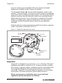
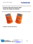
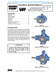
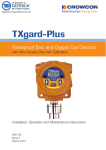
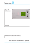
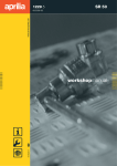
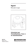
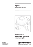
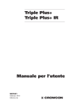
TXgard-IS+ Intrinsically Safe Toxic and Oxygen Gas Detectors Loop Powered Electrochemical and Galvanic Sensor Types Only Installation, operating and maintenance instructions, M07214 Issue 7 January 2010 Tel: +44 (0)191 490 1547 Fax: +44 (0)191 477 5371 Email: [email protected] Website: www.heattracing.co.uk www.thorneanderrick.co.uk Contents 1 Introduction .................................................................................. 5 Product overview ........................................................................................ 5 Product description ..................................................................................... 5 2 Installation ................................................................................... 8 General ....................................................................................................... 8 Mounting ..................................................................................................... 9 Cabling requirement ................................................................................... 9 Electrical connections ............................................................................... 10 3 Operation ................................................................................... 13 The operator display panel and keypad ................................................... 13 Using the TXgard-IS+ menus ................................................................... 14 4 Commissioning .......................................................................... 16 Commissioning procedure: Toxic gas detectors .................................................................................. 16 Commissioning procedure: Oxygen detector ....................................................................................... 21 5 Maintenance .............................................................................. 24 Routine maintenance ................................................................................ 24 Sensor replacement and servicing of detectors ....................................... 24 6 Fault finding ............................................................................... 26 Appendices Appendix A Wiring the TXgard-IS+ to Crowcon control equipment ............ 31 Appendix B TXgard-IS+ specification.......................................................... 35 Appendix C Spare parts .............................................................................. 37 Appendix D Menu system............................................................................ 38 Appendix E 4-20 mA Loops......................................................................... 46 Appendix F Cabling requirement................................................................. 48 Appendix G Sensor limitations..................................................................... 51 Warranty Statement ................................................................. 51 Introduction 1 TXgard-IS+ INTRODUCTION 1.1 Product overview TXgard-IS+ is an Intrinsically Safe detector for toxic gases or oxygen. It is suitable for use in Zone 0, 1 or 2, or Division 1/Division 2 hazardous areas when used with a suitable Zener barrier or galvanic isolator. TXgard-IS+ is designed to detect a wide range of gases when fitted with the appropriate electrochemical sensor. Gases include oxygen, carbon monoxide and hydrogen sulphide. For a full list of supported sensors, please contact Crowcon. TXgard-IS+ is a loop-powered instrument providing a 4-20 mA signal suitable for direct connection to a control panel. Unlike most other 4-20 mA gas detectors featuring operator display panel (LCD) and keypads, it combines its power and signal in just two wires, so only one barrier is required. The instruments are supplied with the mA pre-calibrated, so the mA does not need re-calibration in the field. The keypad and operator display panel allow access to many powerful features to help installation and maintenance, such as: • true one man calibration • signal current can be ramped to a desired value to help set-up control panels • configurable fault and inhibit currents • configurable display options • displaying line voltage - no need to access test points inside unit 1.2 Product description TXgard-IS+ comprises of two main parts. The junction box contains the circuitry, including the PCBs, an operator display panel and keypad. The sensor is contained in the sensor housing. “Figure 1.1” on page 6. The sensor comes in a re-usable bayonet sensor housing which is standard for all gas sensors. The sensor housing screws into an M20 entry on the junction box. All electrical connections to the detector are made through the terminal blocks on the baseboard J2 and J4 (see and in “Figure 1.1” on page 5). The junction box of TXgard-IS+ has one top-entry M20 cable Issue 7 5 TXgard-IS+ Introduction entry for customer use as standard. Side entry versions and gland adapters are available (contact Crowcon for details). The Personality Module , mounted on the baseboard, comes in two varieties: Toxic and Oxygen. It converts the sensor output into a standard signal which can be interpreted by the processor. The Personality Module contains a memory chip with calibration data for the associated sensor. When replacing a sensor, it is not necessary to change the Personality Module; you simply rezero (Note: not necessary for O2 sensor) and recalibrate, and the Personality Module stores the new calibration constants. When the detector is powered through a suitable Zener barrier or galvanic isolator, the system is certified Ex ia IIC T4. Figure 1.1: TXgard-IS+ fitted with toxic sensor 40-200mV TEST POINTS M20 CABLE ENTRY CONNECTION TO CONTROL PANEL Some baseboards may have J4 in this orientation BASE BOARD 1 TP + 2 TP – RED J4 BLU J2 GRN PERSONALITY MODULE SENSOR HOUSING Important TXgard-IS+ is designed for use in Zone 0, 1 or 2, or Division 1/Division 2 hazardous areas and is certified Ex ia IIC T4 when used with a suitable Zener barrier or galvanic isolator. Installation must be in accordance with the recognised standards of the appropriate authority in the country concerned. TXgard-IS+ should be inspected regularly if used in a dusty environment. For further information, please contact Crowcon. Before carrying out any installation work, ensure that local regulations and site procedures are followed. 6 Issue 7 Introduction TXgard-IS+ Storage Instructions The sensor used in this detector has a maximum non-powered storage life of 3 months. Sensors stored within a detector for longer than 3 months prior to commissioning may not last for the full expected operational life. The warranty period for the sensor begins from the date of shipment from Crowcon. Detectors should be stored in a cool and dry environment where temperatures remain within the 0-20°C range TXgard-IS+ GAS DETECTOR TXgardIS+ ATEX, UL and IECEx Intrinsically safe Issue 7 7 TXgard-IS+ 2 Installation INSTALLATION 2.1 General The detector should be mounted where the gas is most likely to be present. The following points should be noted when locating gas detectors: • To detect gases that are lighter than air, detectors should be mounted at high level. Crowcon recommends the use of a Collector Cone (part no. C01051). • To detect gases that are heavier than air, detectors should be mounted at low level. • To detect gases with similar weight to air, for example, hydrogen sulphide, mount the detector at normal breathing height. • When locating detectors, consider the possible damage caused by natural events such as rain or flooding. For detectors mounted outdoors, Crowcon recommends the use of a spray deflector (part no. C01338). • Mounting of oxygen detectors requires knowledge of the gas displacing the oxygen. For example, carbon dioxide is heavier than air and displaces oxygen at low level. Under these circumstances oxygen detectors should be placed at low level. • Consider ease of access for functional testing and servicing. • Consider how the escaping gas may behave due to natural or forced air currents. Mount detectors in ventilation ducts if appropriate. • Consider the process conditions. Gases that are normally heavier than air, but are released from a process line that is at a high temperature and/or under pressure, may rise rather than fall. Ammonia released from a cooling system may fall rather than rise. The placement of the sensors should be decided following the advice of experts with specialist knowledge of gas dispersion, experts with knowledge of the process plant system and equipment involved, and safety and engineering personnel. The agreement reached on the locations of sensors should be recorded. Crowcon is pleased to assist in the selection and siting of gas detectors. 8 Issue 7 Installation TXgard-IS+ 2.2 Mounting TXgard-IS+ should be installed at the location with the detector pointing down. This ensures that dust or water will not collect on the sensor and stop gas entering the detector. Figure 2.1: TXgard-IS+ dimmensions 2.3 Cabling requirement Cabling to TXgard-IS+ must be in accordance with the recognised standards of the appropriate authority in the country concerned, and must also meet the electrical requirements of the detector. Crowcon recommends the use of 2-core twisted pair cable, but there is no particular restriction as long as it can supply 8 V at 20 mA to the instrument terminals. Suitable weatherproof glands must be used. Cable should be identified as being intrinsically safe by some means, for example, by having a blue outer sheath. Alternative cabling techniques, such as steel conduit, may be acceptable provided that appropriate standards are met. TXgard-IS+ requires a dc supply of 8-32 V and is loop powered. (If mounting in a hazardous area, do not use a higher voltage than the Zener barrier’s rating, usually 28 V). Ensure there is a minimum supply of 8 V at the detector, taking into account the voltage drop due to cable resistance and the sense resistance of the control panel to which it is connected. "Table 2.1" on page 10, shows maximum cable distances given typical cable parameters (See appendix F for more information). Issue 7 9 TXgard-IS+ Installation Table 2.1: Maximum cable distances for typical cables Cross-sectional area (mm2) Typical resistance (Ω per km) Maximum distance (km) Cable Loop 1.0 18.1 36.2 2.2 1.5 12.1 24.2 3.3 2.5 7.4 14.8 5.4 The acceptable cross-sectional area of cable used is 1.0 to 2.5 mm2. The table is provided for guidance only. Actual cable parameters for each application should be used to calculate maximum cable distance. Assume each termination is 0.5 Ω. 2.4 Electrical connections All connections to the 4-20 mA loop, and sensor, are made via the screw terminal connectors mounted on the baseboard in the junction box. “Figure 1.1” on page 6. For further information on how 4-20 mA current loops work, see "Appendix E". For a worked example of how to calculate if the cable is suitable, please see “Appendix F”. “Figure 2.2” below, shows the baseboard in detail. The terminals marked J4 should be connected to the control equipment using the appropriate + and – terminals. For further details of wiring the TXgard-IS+ to Crowcon equipment see "Appendix A". Figure 2.2: Baseboard Some baseboards may have J4 in this orientation 10 Issue 7 Installation TXgard-IS+ TXgard-IS+ is a 4-20 mA sink, loop-powered device designed to work in safe and hazardous zones 0, 1 and 2 areas when used in conjunction with an appropriate barrier. Figures 2.3, 2.4 and 2.5 summarise the electrical connections. SAFE AREA Figure 2.3: Electrical connections for safe area HAZARDOUS AREA Note: An IS earth connection must be supplied in the safe area, so as to avoid earth loops and to maintain IS certification. Figure 2.4: Electrical connections using Zener barrier Issue 7 11 TXgard-IS+ Installation Figure 2.5: Electrical connections using galvanic isolator 12 Issue 7 Operation 3 TXgard-IS+ OPERATION 3.1 The operator display panel and keypad The TXgard-IS+ provides an operator display panel through a Liquid Crystal Display (See “Figure 3.1”). The operator display panel allows you to communicate with the TXgard-IS+ instrument through a series of text based menus. Use the operator panel to calibrate the sensor, adjust signal levels and resolve instrument errors. You may also display information on serial number, software version and adjusting advanced settings. The operator display panel provides continual instrument status on the gas being sensed, the gas reading and the loop current value. A flashing ‘OK’ indicates the system is operational (see "Figure 3.2"). Press the down button to display the voltage and temperature (“Figure 3.3” on page 14), this display will automatically return to the main display after a few moments. Figure 3.1: Operator display panel and keypad LCD Liquid crystal display 5 ppm 4.3mA UP key CO OK TXgard-IS+ DOWN key ENTER key Figure 3.2: LCD ‘operator display panel’ UNITS % or ppm Loop current 5 ppm 4.3mA Gas being detected eg. CO, H2S, O2 CO OK TXgard-IS+ Issue 7 Flashing OK indicates system is working 13 TXgard-IS+ Operation Figure 3.3: Power and temperature display (after pressing DOWN key) Power V Power: 21.5V Temp: 25.0 C Temperature TXgard-IS+ 3.2 Using the TXgard-IS+ menus Three buttons are provided to select the menu options and respond to instrument messages, the (UP) and (DOWN) button moves your selection through the menu list, a cursor ‘ >’ indicates current selection. To enter that selection, press the (ENTER) key. To enter the menu system: 1 Press the button and then the default password, which is the down button five times. 2 Press the button again to exit the menu system if you decide not to change the instruments settings. The operator display panel shows the available menus. The TXgard-IS+ has seven standard menus that allow you to calibrate and configure the instrument. The menu structure for a TXgard-IS+ Toxic detector is shown in “Figure 3.4” on page 14, detailed menus can be found in Appendix D. NOTE: the menu for the oxygen detector only varies for the ‘Zero/cal gas’ menu item which is replaced by ‘Cal O2 @ 20.9%’. To exit the main menu display 1 To exit any menu, use the key to move the cursor to the top of the menu list where you will find To gas display. If you are in a submenu you will need to repeat this and move the cursor to the top of the menu list to return to the gas display. Note: UP = OUT. Tip To go directly to the bottom of a menu, press and simultaneously. To go directly to the top of a menu, press and simultaneously. The menu will also return to the gas display after a timeout (default 5 minutes). 14 Issue 7 15 Issue 7 S/W version Displays software version Configuration Submenu To main menu Limit 4-20mA Set inhibit mA Zero suppress Damping Menu timeout Fatal mA Non-fatal mA Display option LCD Contrast Pwr-on inhibit Help screen Oxygen detectors Toxic detectors NORMAL DISPLAY Serial number Displays serial number Serial number S/W version Clear faults Calibrate mA Configuration Ramp mA output Zero/cal gas (cal O2 @ 20.9% gas) Inhibit mode To gas display MAIN MENU To enter Main Menu press ENTER key then DOWN key 5 times See Appendix D and Section 4.2 for further information. Cal O2 @ 20.9% gas Submenu To main menu Confirm O2 cal Calibration of 20.9% gas Zero / Cal gas Submenu To main menu Zero gas Calibrate gas Calibration of zero gas and sensed gas CO OK TXgard-IS+ 0 ppm 4.0mA Figure 3.4 Menu structure for TXgard-IS+ toxic detector Display shows two lines of the menu list at a time, use DOWN key to display other menu items Clear faults Clears faults from display and unit Calibrate mA Submenu To main menu Calibrate 4mA Calibrate 20mA Calibration of 4-20mA loop current Ramp mA output Manual ramp of mA output Inhibit mode Forces instrument to output Inhibit current - To gas display Inhibit mode TXgard-IS+ Operation TXgard-IS+ 4 Commissioning COMMISSIONING The commissioning procedures for toxic detectors can be found in section 4.1. To commission oxygen detectors go to section 4.2. Warning Before carrying out any work, ensure that local regulations and site procedures are followed. Ensure that the associated control panel is inhibited to prevent false alarms. 4.1 Commissioning procedure: Toxic gas detectors NOTE: To prevent false alarms during calibration, enable inhibit mode prior to zeroing or applying gas (see Figure 3.4). The detector output will then remain at the preset inhibit level (see Appendix D) for five minutes or until inhibit mode is cleared manually. “Inhibit” will appear on the normal operating display when inhibit is active, and the detector will automatically resume gas level output after five minutes. Step 1: Connecting the detector to the control panel 1 Apply power to the detector via 2-way connector J4. “Figure 1.1” on page 6. The instrument requires a minimum of 8 V dc at connector J4 at 20 mA. Tip As long as the instrument is running, you can see the supply voltage on the display panel, by pushing the button. 2 Leave the detector to stabilise for at least 2 hours. NOTE: the detector is factory pre-set to automatically inhibit its mA output for 30 seconds after power-up to prevent false alarms while the sensor is settling. Step 2: Checking the 4-20 mA loop current This step can be omitted as the TXgard-IS+ is delivered pre-calibrated, however, if you wish to check the 4-20 mA loop 16 Issue 7 Commissioning TXgard-IS+ current, then it can be checked as outlined below. Alternatively the TXgard-IS+ provides a facility to force a known current through the loop. Refer to the Ramp mA menu item in Appendix D for instructions. NOTE: there is no need to disconnect a sensor when calibrating mA! The mA control circuit is completely independent from the gas measuring circuit! 1 Connect a digital voltmeter (DVM) across test points TP1 and TP2 on the baseboard (“Figure 1.1” on page 6 or “Figure 2.2” on page 9). The loop current flows through a sense resistor between these test points, so a 4 mA loop current will show as 40 mV on the DVM, and 20 mA will show as 200 mV. Step 3: Zeroing the detector in clean air Before commencing zeroing the detector, ensure the instrument is in clean air. NOTE: Oxygen sensors do not need manual zeroing with the TXgard-IS+. See section 4.2 for calibration instructions. 1 Enter the menu system by pressing the button. 2 At the password prompt enter the password, by default this is the down button 5 times. 3 You should now be in the main menu. Refer to menu structure, (“Figure 3.4” on page 15). >To gas display Inhibit mode TXgard-IS+ 4 Move the cursor down and select the Zero/Cal gas menu item. The submenu list for zeroing and calibrating the gas appears. 5 Select the Zero gas menu item. The instrument will display a scrolling text message: ‘Ensure the instrument is in clean air and the sensor has settled’. Issue 7 17 TXgard-IS+ Commissioning 6 Press the button to start zeroing the detector. The instrument will display the following message: Zeroing Sensor.. TXgard-IS+ When complete the instrument will report a scrolling text message ‘Zero operation successful’. 7 Press the button to continue, the display will return to the Zero/cal submenu. >To main menu Zero gas TXgard-IS+ 8 You may now proceed to calibrate the gas on the detector. Step 4: Calibrate gas on the detector Before commencing calibrating gas on the detector ensure you have sample gas. For Oxygen sensors go to section 4.2. NOTE: Whilst in calibrate mode, the instrument outputs the Inhibit current. If you have just completed step 3 (Zeroing) you will still be in the Zero/Cal Gas submenu, and can skip to 5. 1 Enter the menu system by pressing the button. 2 At the password prompt enter the password, by default this is the down button 5 times. 18 Issue 7 Commissioning TXgard-IS+ 3 You should now be in the main menu >To gas display Inhibit mode TXgard-IS+ 4 Select the Zero/Cal gas menu. The submenu list for zeroing and calibrating the gas appears. 5 Move the cursor down and select the Calibrate gas menu item The panel will display a scrolling text message: ‘Apply calibration gas to instrument ––’. 6 Apply calibration gas (typically half or full scale) to the detector at a flow rate of 0.5 litre/minute. (Crowcon Flow Adaptor part No. C03005) Tip Sticky gases which are rapidly absorbed by connecting pipes (chlorine, nitrogen dioxide and ozone) are applied at 1 litre / minute. 7 Select the button. 0.5 Litre/min 150 PPM 13.6mA CO OK TXgard-IS+ Crowcon Flow Adaptor GAS To clean air or exhaust pipe Allow gas reading to stabilise. Issue 7 19 TXgard-IS+ Commissioning Use and buttons to adjust gas reading to calibration gas value. Gas value is usually measured in ppm or as %vol (ppb and %LEL are also available, as appropriate). Tip See "Table 4.1" on page 21 for some gases and their typical range. Please note that detectors can be provided in different ranges if required. Contact Crowcon for list of all gases detected. 8 Select the button to set the calibration value. The instrument will display the following message: Calibrating.. TXgard-IS+ When complete the instrument will report a scrolling text message: ‘Calibration successful! Remove gas from the instrument ––’. 9 Remove the gas from the detector and exit the menu system. The instrument is now calibrated. If the control equipment display requires adjustment, consult the operating manual for the control display equipment. 20 Issue 7 Commissioning TXgard-IS+ Table 4.1: Typical gas ranges Gas Code Gas Unit Standard Ranges† O2 Oxygen %vol 0-25 CO Carbon monoxide ppm 0-250 H2S Hydrogen sulphide ppm 0-25 SO2 Sulphur dioxide ppm 0-10 and 0-100 CL2 Chlorine ppm 0-5 †Note: other ranges are available on request 4.2 Commissioning procedure: Oxygen detector Step 1: Connecting the detector to the control panel 1 Apply power to the detector via 2-way connector J4. “Figure 1.1” on page 6 The instrument requires a minimum of 8 V dc at connector J4 at 20 mA. Tip As long as the instrument is running, you can see the supply voltage on the LCD, by pushing the button. 2 Leave the detector to stabilise for at least 2 hours. Step 2: Checking the 4-20 mA loop current This step can be omitted as the TXgard-IS+ is delivered pre-calibrated, however, if you wish to check the 4-20 mA loop current, then it can be checked as outlined below. Alternately the TXgard-IS+ provides a facility to force a known current through the loop. Refer to the Ramp mA menu item in Appendix D for instructions. Issue 7 21 TXgard-IS+ Commissioning NOTE: there is no need to disconnect a sensor when calibrating mA! The mA control circuit is completely independent from the gas measuring circuit! 1 Connect a digital voltmeter (DVM) across test points TP1 and TP2 on the baseboard (“Figure 1.1” on page 6 or “Figure 2.2” on page 9). The loop current flows through a sense resistor between these test points, so a 4 mA loop current will show as 40 mV on the DVM, and 20 mA will show as 200 mV. Step 3: Calibrate Oxygen NOTE: Unlike previous models it is not necessary to manually “Zero” Oxygen units. 1 Enter the menu system by pressing the button. 2 At the password prompt enter the password, by default this is the down button 5 times. 3 You should now be in the main menu >To gas display Inhibit mode TXgard-IS+ 4 Move cursor down and select the Cal O2 @ 20.9% gas menu. The submenu list for calibrating oxygen appears. 5 Select the Confirm O2 cal menu item. The instrument will display a scrolling text message: ‘Ensure the instrument is in clean air and the sensor has settled’. 22 Issue 7 Commissioning TXgard-IS+ 6 Press the button to start calibrating the detector. The instrument will display the following message: Calibrating.. TXgard-IS+ When complete the instrument will report a scrolling text message: ‘Calibration successful’ 7 Press the button to continue and exit the menu system. The instrument is now calibrated. If the control equipment display requires adjustment, consult the operating manual for the equipment. Issue 7 23 TXgard-IS+ 5 Maintenance MAINTENANCE Repair of instruments: it is a condition of Certification that damaged instruments may only be repaired by trained personnel. Whilst replacement of sensors or personality modules is permitted by untrained personnel, board-level repairs must be carried out at main Crowcon offices, which are listed on our website at www.crowcon.com. 5.1 Routine maintenance The operational life of the sensors depends on the application, frequency and amount of gas being seen. Under normal conditions (6-monthly calibration with periodic exposure to test gas) the life expectancy of the toxic sensors is 2-3 years, and 2 years for the oxygen sensors. Site practices will dictate the frequency with which detectors are tested. Crowcon recommends that detectors be gas tested every month and recalibrated every six months. To recalibrate a detector, follow the steps in Section 4.1 (for a toxic gas detector) or Section 4.2 (for an oxygen detector). In dusty environments, the detector should be tested more frequently to ensure that the sensor does not become blocked. There is no need to recalibrate mA. 5.2 Sensor replacement and servicing of detectors To prevent spurious alarms whilst changing sensors, either - put the control system into Inhibit mode for this channel (preferred), or - put the TXgard-IS+ into Inhibit mode (See Appendix D), or - put the TXgard-IS+ into Ramp mA mode to hold its output at 4 mA or 17.4 mA, as appropriate (typical ungassed toxic / oxygen "safe" signals). NOTE: Ramp mA or Instrument Inhibit modes might time out before the sensor settles, so inhibiting at the control panel end is preferable. 5.2.1 Detectors with bayonet type sensor housings NOTE: There is no need to open the main body of the instrument to replace these sensors. 24 Issue 7 Maintenance TXgard-IS+ 1. Open the sensor housing by pushing in and turning simultaneously to release the bayonet fitting and expose the sensor. 2. Remove the sensor from the sensor housing. 3. Fit the replacement sensor, checking the part number is correct. This part number is labelled on the main body of the detector. Observe the correct pin alignment with the PCB. 4. Reassemble the sensor housing. 5. The sensor should now be re-zeroed and calibrated. See “Commissioning” on page 16. For Oxygen sensors see “Commissioning procedure: Oxygen detector” on page 21). Issue 7 25 6 Issue 7 “Supply V Low” The voltage on the 4-20 mA line is too high (>32 V) or too low (<8 V) for reliable operation. Note: some long cables have significant resistance, and can supply 8 V at the instrument terminals at 4 mA, but not 20 mA. Use the Ramp mA function to confirm line voltage is OK at 20 mA. (See appendix D) Adjust power supply. Instrument is in calibrate mode. Complete the calibration operation. Instrument outputs an inhibit current “Supply V High” Examine display to determine fault and take action as described below. Note: the Fault/inhibit currents can be set to 2, 3, 4, 24 mA or Gas Level in the Configuration menu (see Appendix D) Instrument outputs a Fault signal 4-20 mA signal is frozen Reverse the polarity by swapping the wires over. Check supply voltage. Solution The cause is usually no power, ie the wires are the wrong way round. Cause Nothing is displayed - instrument appears dead Symptom / error message Fatal errors are severe enough that the gas reading cannot be trusted but can sometimes be cleared by removing power and reconnecting it. Non Fatal errors are simply warnings that the instrument has noticed a problem, but can continue / recover by using backup data. FAULT FINDING Fault finding TXgard-IS+ 26 27 The last zero operation did not succeed – there would have been a scrolling message on completion of the zero operation giving an error whilst still in the menus The last calibration operation did not complete successfully – there would also have been a scrolling message on completion of the calibrate stating that the operation had failed. “Cal. warning” The temperature is too low or high for the instrument to work reliably. Cause “Zero warning” “Temp. high err” “Temp. low err.” Symptom / error message Issue 7 Occasionally, sensors die completely, but this normally requires serious abuse (e.g. extreme heat, or very high overloads of gas). Replace sensor. Sensors have a finite lifetime: their output gradually decays and eventually they need replacing. Recalibrate the sensor: Check the calibration gas is at an appropriate concentration and is applied to the sensor at the correct flow rate 0.5-1.0 litres/ minute. Re-zero sensor. Check sensor is in clean air and has settled. Note: Some sensor types do not work over this entire range. Ensure temperature is between – 20°C and +55°C (–4°F to 131°F). Solution TXgard-IS+ Fault finding Issue 7 Gas calibration data stored in the sensor module’s non-volatile memory has been corrupted. mA calibration data stored in the instrument’s non-volatile memory has been corrupted. FRAMs are non volatile memory. The instrument has detected corruption in one. FRAM1 is on the main PCB and stores the instrument configuration. FRAM2 is in the Personality Module and stores sensor data (Calibration constants, gas name etc.). “Gas calib. err” (Fatal) “mA Calib error” “FRAM1 fault” “FRAM2 fault” The signal is very high or low for the level of gas you are applying. A scrolling message would have been displayed on completion of the zero or calibrate operation giving this fault. Cause “Cal gain error” Symptom / error message Alternatively, use the Clear Faults menu option (see appendix D). Disconnect power and reconnect it. The FRAM with an error should restore its data from backup in the other FRAM. mA calibration must be checked, using the Ramp mA function (see Appendix D), and re-calibrated or instrument must be returned to Crowcon for service. Sensor must be re-zeroed and calibrated. Without calibration data the instrument cannot correctly measure gas. Check you are using the right level of gas, and that you are inputting the correct number through the keypad. Ensure sensor has been properly zeroed before calibrating. Solution Fault finding TXgard-IS+ 28 29 Issue 7 Alternatively: the instrument cannot see the sensor. If a wornout sensor has just been replaced, confirm that a new one has been placed correctly in the sensor housing. Check connections to sensor have not come loose or have been incorrectly wired (“Figure 1.1” on page 6) “Sensor Fault” (Fatal) The instrument should finish correcting the mA signal after a few minutes. It is deliberately slow to prevent transient events giving problems. If the problem persists, use the Ramp mA menu item to confirm the instrument is drawing the current it thinks it is (see “Appendix D”). The 4-20 mA signal can be recalibrated if necessary. If there is still a problem, check the cable for ground loops or earthing problems. Solution Personality module has failed and needs replacing The instrument is recalibrating its 4-20 mA signal, because it has detected a discrepancy between what it should be and what it is. This could be a result of earth loop currents, for example. Cause “Amplifier error” (Fatal) “mA high error” “mA low error” Symptom / error message TXgard-IS+ Fault finding Issue 7 Re-zero and re-calibrate. You may need to perform this procedure twice to reach a stable reading Personality module contains data for different unit Wrong contrast setting Faulty circuit, LCD or extremely poor contrast setting Calibration is difficult whilst applying gas, numbers alter too fast when using up and down arrows Display contrast poor Display blank/cannot be read at any angle Error and Fault messages will remain on the operator display panel until they are cleared. Selecting Clear Faults from the menu will remove them. However, if the fault re-occurs the fault message will be displayed again. Fault current can be configured to be different for Fatal / Non Fatal events, see Appendix D. Send to Crowcon for reconfiguration Check and reconfigure contrast setting in Configuration menu Re-zero and re-calibrate instrument Unstable mA or gas reading Recalibrate instrument. Solution Check the full scale reading required for example, 0-50 ppm, and the sample gas value, for example, gas is supplied as 25 ppm The instrument gas calibration is not set to the correct scale, for example, expected range is 0-25 ppm, range may be set at 0-50 ppm Cause The sample gas is half scale mA is unexpectedly low for gas reading Symptom / error message Fault finding TXgard-IS+ 30 TXgard-IS+ Appendix A APPENDIX A WIRING THE TXGARD-IS+ TO CROWCON CONTROL EQUIPMENT This appendix describes how to connect the TXgard-IS+ to the following Crowcon control panels: Vortex, Gasmonitor, Gasmaster and Gasflag. The instructions for connecting the cards and setting the links are outlined below. Connection details for the Ditech range of control equipment will be included on the wiring diagrams supplied for the system. Connecting the TXgard-IS+ to a Crowcon Vortex The TXgard-IS + is connected to the Vortex control panel using a Quad Channel Module, see “Figure A.1”. The module consists of four channels, each with a 3-way connector. The detector may be connected to any of the four channels shown in “Figure A.1”. Figure A.1: Quad Channel Module Wires use left hand two positions -+ -+ Channel 1 Channel 2 Module selection Wires use right hand two positions Detector type switches Channel 3 Channel 4 + - +- NOTE: Vortex has certain current levels hard-wired as signals. However, TXgard-IS+ is highly configurable and can be programmed to work with most control panels. When connecting to a Vortex, set the TXgard-IS+ as follows: Fatal and Non Fatal Fault Currents = "3 mA" Inhibit current = “24 mA” or "Clean air level". The latter is better for long cable runs (less IxR drop). 31 Issue 7 Appendix A TXgard-IS+ Set the Detector Type Switch for the appropriate channel to position 2. The switch can be found in the hatch on the side of the Quad Channel Module, see “Figure A.1”. Connecting the TXgard-IS+ to a Crowcon Gasmonitor The TXgard-IS+ is connected to the Gasmonitor control panel via an INPUT/OUTPUT MODULE at the rear of the Gasmonitor racking system. The links for Toxic and Oxygen detectors are the same, configure the INPUT card as follows: LINK Make these connections LK1 LK2 LK3 LK4 LK5 LK6 LK7 A, C E, I, K none “4-20” “24V” “C/C” “24V” At the rear of the Gasmonitor, connect the instrument to the INPUT/ OUTPUT MODULE, the section labelled DETECTING HEADS (See "Figure A.2"). Choose the channel matching the input card. The module consists of three rows of 16 channels, the terminals to use are marked 60-107. The top row (terminals 50-55) is not used with the TXgardIS+. The second row provides 24 V, the third row provides 0 V. The first two terminal blocks are reserved. The remaining 16 channels marked 1-16 can be used to connect the TXgard-IS+, for example, to connect channel 2, connect the positive wire to terminal 64 and the negative wire to terminal 63. "Figure A.2" shows a TXgard-IS+ connected to channel 2. NOTE: Gasmonitors will only recognise a 24 mA signal from TXgard-IS+ as Fault. Although Gasmonitors can also be configured to use "less than 2mA" as a Fault signal, the minimum current that the TXgard-IS+ can draw is 2.2 mA, so TXgard-IS+ will not trigger Gasmonitor's Fault if the TXgard-IS+ Fault signal is set to 'minimum' (2.2 mA). Issue 7 32 TXgard-IS+ Appendix A Figure A.2: Electrical connections for Gasmonitor DETECTOR HEADS 107 104 101 98 95 92 89 86 83 80 77 74 71 68 65 62 106 103 100 97 94 91 88 85 82 79 76 73 70 67 64 61 24V 105 102 99 96 93 90 87 84 81 78 75 72 69 66 63 60 0V Channel 16 15 14 13 12 11 10 9 8 7 6 5 4 3 2 1 Connecting the TXgard-IS+ to a Crowcon Gasmaster The TXgard-IS+ is connected to a Gasmaster control panel as shown below. The Gasmaster input channel link should be set to 'SINK' and the input channel should be configured as 'DET 4-20 SINK'. For hazardous area installations refer to the Gasmaster manual. Figure A.3: Electrical connections for Gasmaster Channel Link Settings EXTERNAL BARRIER FIRE SINK SRCE Safe Area TXgard-IS+ SCR 0V SIG PWR + 4-20 mA Current Sink Gasmaster Detector Input Terminals 33 Issue 7 Appendix A TXgard-IS+ Connecting the TXgard-IS+ to a Crowcon Gasflag The TXgard-IS+ is connected to the Gasflag via the screw terminals marked SENSOR +VE (this is the TXgard-IS+ positive supply) and SENSOR SIG (which connects to TXgard-IS+ negative supply). Set links LK10A and LK10B to SOURCE, position B. Figure A.4: Electrical connections for GasFlag Issue 7 34 TXgard-IS+ Appendix B APPENDIX B TXGARD-IS+ SPECIFICATION Dimensions 160 x 123 x 92 mm (7.3 x 5 x 3.6 inches) Weight 700 g Operating voltage 8-32 V dc, loop-powered, 4-20 mA Normal Output Signal 4-20 mA current sink Fault current Minimum, 3 mA, 24 mA, or normal gas signal (configurable) Operating temperature –40°C to +65°C (–40°F to 149°F) Note: Instrument operates and has been certified as Intrinsically Safe between –40°C and +65°C, giving out a 4-20 mA signal proportional to measured gas; but LCD will go blank at about –20°C. The sensor's performance changes at extremes of temperature; consult Crowcon if the detector will be exposed to ambient temperatures below -20°C or above +40°C Humidity 15-90% RH, non-condensing for most sensors Display 2 x 16 character LCD Response time (typical) (T90): approximately 20 seconds for most Toxic sensors, 10 seconds for Oxygen* Repeatability ±2% FSD, 6 months* Cable loop resistance 300 Ω with 22 V supply at 20 mA Degree of protection IP65 (when fitted with Weatherproof Cap) Explosion protection Intrinsically Safe Approval codes II 1G Ex ia IIC T4(-40°C to +65°) UL/cUL: Cl I, Div 1 Groups A,B,C,D Safety certification nos. 35 Baseefa 08 ATEX 0069X, UL E147777 IECEx BAS 08.0028X "X" Special Conditions for Safe Use: Warning: Static Hazard Clean Only with a Damp Cloth. Issue 7 Appendix B Standards TXgard-IS+ EN60079-0 (safety in flammable atmospheres) EN60079-11 (intrinsic safety) EN50022 (emissions) IEC61000-4 (immunity) EN50270 (EMC for gas detection equipment) EN50271(software design standard) UL (UL913 Ed 7) cUL (CSAC22.2 No.157) class 1 group A,B,C and D This device complies with part 15 of the FCC Rules. Operation is subject to the following two conditions: (1) This device may not cause harmful interference, and (2) this device must accept any interference received, including interference that may cause undesired operation. This Class A digital apparatus complies with Canadian ICES-003. Cet appareil numérique de la classe A est conforme à la norme NMB-003 du Canada. Zones ATEX/IECEx: 0, 1 & 2 UL: Class 1 Gas groups ATEX/ IECEx: IIC UL: A,B,C & D Zener barriers or galvanic isolators Max 28 V; 93 mA 0.66 Watts *Specifications are typical, and may vary for different sensor types. Issue 7 36 TXgard-IS+ Appendix C APPENDIX C SPARE PARTS AND ACCESSORIES Please contact Crowcon for details of the latest replacement sensors. Please quote the part number given on the "Sensor Replacement label" mounted on the outside of the sensor housing. 37 Description Part Number M20 to ½" NPTF adaptor M02125 M20 to ¾" NPTF adaptor M02281 Ceiling mounting bracket M01401 Collector cone C01051 Spray deflector C01338 728 Zener barrier for use with 24 V dc systems C03221 5041 Galvanic isolator C03278 Mounting box for 2 Zener barriers C03224 Mounting box for 5 Zener barriers C03225 Mounting box for 12 Zener barriers C03226 Mounting box for 4 galvanic isolators C01560 Mounting box for 8 galvanic isolators C01561 Calibration gas Contact Crowcon Bayonet sensor housing 3-wire S01343 Bayonet sensor housing 2-wire (oxygen sensor) S012027 Issue 7 Appendix D TXgard-IS+ APPENDIX D MENU SYSTEM This section provides greater details for the TXgard-IS+ menu items and is a supplement to the section “Using the TXgard-IS+ menus” on page 14. You may wish to refer to the Menu Map on the back cover to familiarise yourself with the menu hierarchy. This appendix also works in conjunction with the Fault Finding guide on page 26. To enter the TXgard-IS+ Menu System Press the button and then the default password which is the down button five times. To select a menu item use the UP and DOWN buttons to move the cursor ‘ >‘ to the desired menu item and press the button. Inhibit mode Description: Forces instrument to output the Inhibit current. This menu option provides a convenient option to allow an engineer to force the instrument to output the Inhibit current whilst he carries out maintenance on the TXgard-IS+. This will prevent unwanted alarms being seen at the control panel whilst, for example, the sensor is changed. It provides an alternative to setting the instrument into Calibrate mode which also outputs the Inhibit current. Instructions 1. Enter the TXgard-IS+ menu system by pressing the key followed by the down key five times. 2. Move the cursor down and select the Inhibit mode menu item. By selecting Enable Inhibit mode the detector output will be forced to a level set in the Set Inhibit mA menu. “Inhibit” will then be shown on the normal gas level display. Inhibit mode will time-out after five minutes, or can be manually reset using the inhibit mode option. Issue 7 38 TXgard-IS+ Appendix D The display should look as follows; Inhibit active Press to go on TXgard-IS+ Gas Calibration Menus Description: The gas calibration menus provide the instructions and means to calibrate the instrument. This menu is different for toxic detectors and oxygen detectors. The Toxic detector has two menu items, one to zero the unit and the other to set the calibration gas level. The oxygen detector has only one menu item to set the oxygen level. It is not required to manually zero an oxygen detector. See Sections 4.1 and 4.2 for detailed step-by-step instructions for using these menus. Menu: (Toxic detectors) Zero/Cal gas Submenu To main menu Zero gas Calibrate gas Zero gas This menu provides instructional guidelines to zero an instrument. Calibrate gas This menu provides instructional guidelines to calibrate the gas on the instrument. Menu: (Oxygen detectors) Cal O2 @ 20.9% gas Submenu To main menu Confirm O2 cal Cal O2 @ 20.9% gas This menu provides instructional guidelines to set the oxygen level on an oxygen detector. Note: clean air is always considered to be 20.9% oxygen. 39 Issue 7 Appendix D TXgard-IS+ Ramp mA output Description: This menu item allows you to force the output loop current to a known value. It does not calibrate the 4-20 mA loop current or affect any calibration values within the TXgard-IS+ detector. The TXgard-IS+ provides convenient test points within the instrument to measure the loop current. The test points TP1 and TP2 can be found on the baseboard (“Figure 1.1” on page 6 and "Figure 2.2" on page 10). The loop current flows through a sense resistor between these test points, so a 4 mA loop current will show as 40 mV on the DVM, and 20 mA will show as 200 mV. When would I use it? Ramp mA output can be used to help calibrate and set up the control panel used with a TXGard-IS+ detector by forcing a known current through the loop. It is also useful for locking the output to a known level which will not trigger alarms whilst, for example, changing the sensor. It is also useful if you suspect the current is no longer calibrated. In this case it can be checked at test points TP1 and TP2. It is useful during installation to force the loop current to the maximum value (20 or 24 mA, depending on configuration). The installer can then confirm line voltage is at least 8 V at the instrument terminals at maximum current, even with maximum voltage drops in the loop. Instructions 1. Enter the TXgard-IS+ menu system by pressing the key followed by the down key five times. 2. Move the cursor down and select the Ramp mA output menu item by pressing . The display should look as follows; mA: 4.0 (22.7V) Use , to edit TXgard-IS+ NOTE: The display shows the loop current and the voltage on the 4-20 mA line at the detector. The voltage will fall as the instrument takes more current due to the voltage drops in the Zener barrier and Issue 7 40 TXgard-IS+ Appendix D cable. The voltage must remain greater than 8 V at the instrument terminals for the instrument to function. 3. Use the UP and DOWN keys to adjust the loop current value. The current value will increment in 0.5 mA steps. The default value of the loop current when the menu is first entered is 4 mA. The loop current can be forced to 24 mA or reduced to 3.5, 3.0 and Minimum output. Press the key when finished. NOTE: on oxygen detectors, a signal of 4 mA is likely to generate a low oxygen alarm at the control equipment. 4. Exit the menu system. Configuration The TXgard-IS+ detector provides a configuration menu to set various options. Below is a list of options, the values that can be set and a description. Menu: Configuration Submenu To main menu Limit 4-20 mA Set inhibit mA Zero suppress Damping Menu timeout Fatal mA Non-fatal mA Display option LCD Contrast Pwr-on inhibit Help screen 41 Issue 7 Appendix D TXgard-IS+ Menu item Options Description To Main Menu Exit Exit to main menu. Limit 4-20 mA Enable / Disable If enabled, the instrument will only ever draw a maximum of 20 mA, no matter what the gas value. Set inhibit mA Minimum, 3 mA, Clean Air mA, or Gas Level When the instrument is in inhibit mode or calibration mode, the instrument outputs an inhibit current to prevent false alarms whilst gas is applied. When inhibit current value is set to ‘Gas Level’ the loop current is not inhibited. Zero suppress None, Minor or Major Defines the size of the dead band about the zero point of the device. This will suppress unwanted spurious signals and improve stability at zero.Suppression may be set to 3 levels, with increasing levels of suppression. Damping None, Light, Medium or Heavy Damping is the means where noisy gas readings may be smoothed out. However, increasing the amount of damping in order to reduce the amount of noise will be at the expense of sensor response time. Menu timeout 30 secs, 1, 5 or 10 minutes/ No timeout This sets the timeout value before a menu display will automatically return to the normal display mode if there is no response or input from the user. ‘No timeout’ will disable the timeout option. Fatal mA Minimum, 3 mA, 24 mA or Gas Level This selects the current the instrument will sink when a fatal error has been detected. Note: the option ‘gas level’ is available; this means the instrument will ignore the error for the purposes of loop current - a display message will still flash as normal. Issue 7 42 TXgard-IS+ 43 Appendix D Menu item Options Description Fatal mA Minimum, 3 mA, 24 mA or Gas Level This selects the current the instrument will sink when a fatal error has been detected. Note: the option ‘gas level’ is available; this means the instrument will ignore the error for the purposes of loop current - a display message will still flash as normal. Non-fatal mA Minimum, 3 mA, 24 mA or Gas Level This selects the current the instrument will sink when a non fatal error has been detected. Note: the option ‘gas level’ is available; this means the instrument will ignore the error for the purposes of loop current - a display message will still flash as normal. Display option No display, Normal display, mA display, This selects what information is displayed on the normal gas display screen. ‘Normal’ means the gas level and flashing ‘OK’ is displayed, ‘mA display’ also displays the loop current and ‘no display’ suppresses all information. LCD Contrast Contrast adjustment Pressing the up and down arrows will increase and decrease the display's contrast. Pressing RETURN [copy in symbol from cell above] will return to last menu. Pwr-on inhibit Enable / disable Selects whether the detector output is automatically inhibited for 30 seconds after power-up. The output current level while in inhibit mode is set using the Set Inhibit mA menu. Help screen Enable / disable If further help is enabled, the menu will display more detailed help messages. The user will be presented with “For error help press , else RETURN ”, if a warning message is displayed. Issue 7 Appendix D TXgard-IS+ Calibrate mA Description: The Calibrate mA menu provides a means of re-calibrating the 4-20 mA loop current. NOTE: The TXgard-IS+ detectors leave the factory with the 4-20 mA signal correctly calibrated. This menu is provided for Service Engineers to adjust the calibration to match site control equipment which cannot itself be correctly calibrated. Menu: Calibrate mA Submenu To main menu Calibrate 4 mA Calibrate 20 mA Instructions The TXgard-IS+ detector provides two test points to measure the signal current. Connect a Digital Volt Meter (DVM) across the test points TP1 and TP2. (“Figure 2.2” on page 10.) The loop current flows through a sense resistor between these test points, so a 4 mA loop current will show as 40 mV on the DVM, and 20 mA will show as 200 mV. 1. Enter the TXgard-IS+ menu system by pressing the key followed by the down key five times. 2. Move the cursor down and select the Calibrate mA menu item. You are now in the Calibrate mA submenu. 3. Move the cursor down and select the Calibrate 4 mA menu item. The display should look as follows; Use , to set 4mA and press TXgard IS+ 4. Use the UP and DOWN keys to adjust the voltage reading on the DVM as required across the test points TP1 and TP2 (nominally 40 mV). Press the key when finished. Issue 7 44 TXgard-IS+ Appendix D 5. To calibrate the 20 mA, select the Calibrate 20mA menu item and repeat step 4 adjusting the voltage reading to 20 mA value (nominally 200 mV). Press the key when finished. 6. Exit the menu system. Clear Faults Description: Clears Faults from display and unit. When the TXgard-IS+ detects a fault, a warning message will be displayed on the operator display panel. Refer to the Fault Finding guide on page 26 to determine cause and solution to the fault. For example, if an instrument detects the line voltage dropping below 8 V, it will flash the warning: Supply voltage low even if the supply voltage recovers, to warn you that there was a problem with the supply. To clear a warning message from the TXgard-IS+ detector To clear the warning message, enter the TXgard-IS+ menu system, move the cursor down and select Clear faults menu item and press the key. NOTE: Error and Fault messages will remain on the operator display panel until they are cleared. Selecting Clear Faults from the menu will remove them, however, if the fault re-occurs the fault message will be displayed again S/W version Description: this menu item displays the software version of the detector. Serial number Description: this menu item displays the serial number of the detector. 45 Issue 7 Appendix E TXgard-IS+ APPENDIX E 4-20 mA LOOPS A 4-20 mA loop is a standard method of connecting remote instruments to a control panel. The basic concept is that a reading of zero gas corresponds to 4 mA, and full scale gas corresponds to 20 mA. The control panel supplies typically 24 volts down 2 wires, and measures the current flowing in the loop. The remote instrument, in this case a gas detector, controls the current: The constant 4 mA is used to run the instrument processor, amplifier etc. This is termed a loop powered, current sink circuit. In this case, the control equipment is providing (or sourcing) the current and the detector is receiving (or sinking) the current. The detector is consequently termed a current sink and the control equipment must be configured to act as a current source. Figure E.1 Current loops are often more resistant to radio frequency interference than a simple voltage reading, and they will generally work down long cables (e.g. over a kilometre). When using current loops, care must be taken that the voltage drop of the maximum signal (usually 20 mA) down the line does not reduce the line voltage below 8 V, which is the minimum working voltage of the TXgard-IS+. See section 2.3 for further information on cabling requirements. NOTE: It is also possible to have 3-wire current loops. In this case, the instrument is powered by one pair of wires (+ supply and 0 V) and the Issue 7 46 TXgard-IS+ Appendix E current signal is measured between the third wire and 0V. Because 3-wire circuits don’t depend on the current in the signal loop to power them, they can also source current. However, they require more expensive Zener barriers to make them intrinsically safe, and cannot be retrofitted into existing 2-wire installations without replacing the cabling. 47 Issue 7 Appendix F TXgard-IS+ APPENDIX F CABLING REQUIREMENT Cabling to TXgard-IS+ must be in accordance with the recognised standards of the appropriate authority in the country concerned, and must also meet the electrical requirements of the detector. Crowcon recommends the use of 2-core twisted pair cable, but there is no particular restriction as long as it can supply 8 V at 20 mA to the instrument. Suitable weatherproof glands must be used. Cable should be identified as being intrinsically safe by some means, for example, by having a blue sheath. Alternative cabling techniques, such as steel conduit, may be acceptable provided that appropriate standards are met. TXgard-IS+ requires a dc supply of 8-32 V and is loop powered. (If mounting in a hazardous area, do not use a higher voltage than the Zener barrier’s rating, usually 28 V). Ensure there is a minimum supply of 8 V at the detector, taking into account the voltage drop due to cable resistance and the sense resistance of the control panel to which it is connected. For example, a nominal dc supply at the control panel of 24 V has a guaranteed minimum supply of 18 V. The circuit may demand up to 24 mA (see note 1). Given a sense resistor in the control panel of 250 Ω (dropping 6 V at 24 mA) the maximum voltage drop allowed due to cable resistance is 18-8-6 = 4 V. Thus the maximum loop resistance allowed is 4 V/24 mA = 166 Ω (approximately). Safe installation (only relevant for installations in Hazardous Areas): TXgard-IS+ depends on the principle of Intrinsic Safety to prevent explosions. This means that the energy stored in the instrument never reaches a level which could cause a dangerous spark capable of igniting gas. Since some energy is stored in the cable, the installation must consider the safety of the entire system: Barrier + Cable + Instrument. Fortunately, the calculations are quite straightforward. Connection to the safe area is via a zener barrier or galvanic isolator. The barrier or isolator will have a maximum permissible set of L, C and perhaps L/R values printed on it. Example: MTL type 728 barrier Voc <=28.12 V, Isc <= 93 mA, Ca <= 0.083 uF, La <= 3.05 mH Issue 7 48 TXgard-IS+ Appendix F This means that the barrier output will not exceed 28.12 V or 93 mA into the Hazardous Area, due to the barriers' internal clamps and fuse. At these power levels, you can attach up to 0.083 microfarads of capacitance and 3.05 millihenries of inductance and still be safe. Example: unsafe: a 1 microfarad load would store enough energy (0.5 x C x V2) to potentially cause a spark capable of igniting gas. TXgard-IS+ has been designed to have as low a capacitance and inductance as possible, to permit it to be cabled up with several kilometres of cable. Example: Zener barrier Control panel 2 1 km of 1 mm cable Nominal 24 V supply (guaranteed 22 V output) 250 ohm current sense resistor 300 ohm resistance max permissible load 3.05 mH, 0.083 uF Safe Area TXgard-IS+ 10 uH, 0.1 nF 36.2 ohm (loop) (safety information 860 uH, 60 nF Maximum L/R ratio 25 uH/ohm is marked on label) HazardousArea You must refer to the cable specification to discover the exact values of capacitance and inductance. * In this example, the total inductive load on the output of the zener barrier is 870 uH which is well below its 3,050 uH limit. * The capacitive load is only 60.1 nF which is below the 83 nF limit of the barrier. So the system is Intrinsically Safe. In addition to the safety of the system you must also consider: will it work? As described earlier in Appendix F, you must check that the TXgard-IS+ will get a minimum supply of 8 volts at the end of the cable. Here we can count on 22 V at the control panel, and with a maximum current drain of 20 mA, we will lose (250 + 300 + 36.2 ohms) x 0.02 amps = 11.7 V, so the detector will always have at least 10.3 V. However, we have to ensure it does not have its fault current set to "24mA" or it will only get 7.9 V. For longer cable lengths, use cable with 1.5 or 2.5 mm2 cores (see section 2.3 for resistance values). Note 1. You might only need to allow for up to 20 mA, depending on how the instrument is configured. The signal can be limited to the range 4-20 mA using the "Limit -20 mA" option in the Configuration menu (see "Appendix D"). Otherwise the instrument increases signal (gas) current to a maximum of 24 mA. Fault and Inhibit currents can be programmed to be 24 mA in the Configuration menu if desired, but most control panels use 3 mA or less to signal faults. 49 Issue 7 Appendix F TXgard-IS+ Note 2. It is worth noting that most 28 V Zener barriers are 300 Ω, which will give another 6 V drop. With an 18 V supply and a 250 Ω sense resistor, this would give a voltage at the end of an 80 Ω loop of min. 18 - 6 - 6 - 2 = 4 V, which is not enough to drive the TXgard-IS+ (which requires 8 V or more). Therefore when using Zener barriers and high-value sense resistors, ensure the supply voltage is a good 24 V: thus e.g. 24 - 6 - 6 - 2 = 10 V. Obviously if you have configured the instrument to draw no more than 20 mA (see Note 1), the situation is improved. Note 3. By loop resistance we mean the total resistance of both wires in the twisted pair cable, that is, one wire going to the detector and one returning. For example, an 80 Ω loop resistance will be 40 Ω out and 40 Ω back. Cable resistance values are usually quoted for a single conductor, thus the value has to be doubled to correctly calculate the loop resistance. Issue 7 50 Appendix G TXgard-IS+ APPENDIX G SENSOR LIMITATIONS The sensors used in TXgard-IS+ have limitations common to all such gas sensors, and users should be aware of the points listed below. Crowcon can advise on particular situations and suggest alternative sensors if the instrument is likely to experience extreme conditions. • Electrochemical gas sensors contain chemicals. The chemicals' performance changes at extremes of temperature; consult Crowcon if the detector will be exposed to ambient temperatures below -20°C or above +40°C. • Extreme levels of humidity can also cause problems. The sensors are rated for an (average) ambient of 15-90% R.H. However they are used from the tropics to deserts to tundra without this normally being a problem. • Water should not be allowed to collect on the sensor as this may impede gas diffusion. This is why the sensors are usually mounted on the bottom of the instrument. • Persistent exposure to high levels of toxic gas will shorten the life of the sensor. If the high level gas is corrosive (e.g. hydrogen sulphide) damage may occur over time to metal components. • Sensors may be cross sensitive to other gases. If unsure, contact Crowcon or your local agent. • When used in dusty environments, detectors should be inspected regularly as dust may block the sensor and prevent gas from being detected. Warranty Statement This equipment leaves our factory fully tested and calibrated. If within the warranty period, the equipment is proved to be defective by reason of faulty workmanship or material, we undertake at our discretion either to repair or replace it free of charge, subject to the conditions below. Warranty Procedure To facilitate efficient processing of any claim, contact our customer support team on +44 (0)1235 557711 with the following information: Your contact name, phone number, fax number and email address. Description and quantity of goods being returned, including any accessories. Instrument serial number(s). Reason for return. Issue 7 51 TXgard-IS+ Fault finding Obtain a Returns form for identification and traceability purpose. This form may be downloaded from our website 'crowconsupport.com', along with a returns label, alternatively we can 'email' you a copy. Instruments will not be accepted for warranty without a Crowcon Returns Number ("CRN"). It is essential that the address label is securely attached to the outer packaging of the returned goods. The guarantee will be rendered invalid if the instrument is found to have been altered, modified, dismantled, or tampered with. The warranty does not cover misuse or abuse of the unit. Any warranty on batteries may be rendered invalid if the use of an unauthorized charger is proven. Non-rechargeable batteries are excluded from this warranty. Warranties on sensors assume normal usage, and will be rendered invalid if the sensors have been exposed to excessive concentrations of gas, extended periods of exposure to gas or have been exposed to 'poisons' that can damage the sensor, such as those emitted by aerosol sprays Warranty Disclaimer Crowcon accept no liability for consequential or indirect loss or damage howsoever arising (including any loss or damage arising out of the use of the instrument) and all liability in respect of any third party is expressly excluded. This warranty does not cover the accuracy of the calibration of the unit or the cosmetic finish of the product. The unit must be maintained in accordance with the Operating and Maintenance Instructions. The warranty on replacement consumable items (such as sensors) supplied under warranty to replace faulty items, will be limited to the unexpired warranty of the original supplied item. Crowcon reserves the right to determine a reduced warranty period, or decline a warranty period for any sensor supplied for use in an environment or for an application known to carry risk of degradation or damage to the sensor. Our liability in respect of defective equipment shall be limited to the obligations set out in the guarantee and any extended warranty, condition or statement, express or implied statutory or otherwise as to the merchantable quality of our equipment or its fitness for any particular purpose is excluded except as prohibited by statute. This guarantee shall not affect a customer's statutory rights. Crowcon reserves the right to apply a handling and carriage charge whereby units returned as faulty, are found to require only normal calibration or servicing, which the customer then declines to proceed with. For warranty and technical support enquiries please contact:: Customer Support Tel +44 (0) 1235 557711 Fax +44 (0) 1235 557722 Email '[email protected]' 52 Issue 7 Tel: +44 (0)191 490 1547 Fax: +44 (0)191 477 5371 Email: [email protected] Website: www.heattracing.co.uk www.thorneanderrick.co.uk Cal O2 @ 20.9% gas Submenu To main menu Confirm O2 cal Calibration of 20.9% gas Zero / Cal gas Submenu To main menu Zero gas Calibrate gas Calibration of zero gas and sensed gas CO OK S/W version Displays software version Configuration Submenu To main menu Limit 4-20mA Set inhibit mA Zero suppress Damping Menu timeout Fatal mA Non-fatal mA Display option LCD Contrast Pwr-on inhibit Help screen Oxygen detectors Toxic detectors TXgard-IS+ 0 ppm 4.0mA NORMAL DISPLAY Serial number Displays serial number Serial number S/W version Clear faults Calibrate mA Configuration Ramp mA output Zero/cal gas (cal O2 @ 20.9% gas) Inhibit mode To gas display MAIN MENU To enter Main Menu press ENTER key then DOWN key 5 times Display shows two lines of the menu list at a time, use DOWN key to display other menu items Clear faults Clears faults from display and unit Calibrate mA Submenu To main menu Calibrate 4mA Calibrate 20mA Calibration of 4-20mA loop current Ramp mA output Manual ramp of mA output Inhibit mode Forces instrument to output Inhibit current - To gas display Inhibit mode