1
High-Speed Counter Module
User’s Manual
(Hardware)
QD62
QD62E
QD62D
Thank you for buying the Mitsubishi general-purpose programmable
controller MELSEC-Q Series
Prior to use, please read both this manual and detailed manual
thoroughly and familiarize yourself with the product.
Controller
MODEL QD62 (E/D)-U-H-JE
MODEL
13JQ69
CODE
IB(NA)-0800059-E(0712)MEE
© 1999 MITSUBISHI ELECTRIC CORPORATION
z SAFETY PRECAUTIONS z
(Always read before starting use)
Before using this product, please read this manual and the relevant manuals introduced in
this manual carefully and pay full attention to safety to handle the product correctly.
The instructions given in this manual are concerned with this product. For the safety
instructions of the programmable controller system, please read the CPU module user's
manual.
In this manual, the safety instructions are ranked as "DANGER" and "CAUTION".
Indicates that incorrect handling may cause hazardous conditions,
DANGER
resulting in death or severe injury.
CAUTION
Note that the
Indicates that incorrect handling may cause hazardous conditions,
resulting in medium or slight personal injury or physical damage.
CAUTION level may lead to a serious consequence according to the
circumstances.
Always follow the instructions of both levels because they are important to personal safety.
Please keep this manual in a safe place for future reference and also pass this manual on to
the end user.
[DESIGN PRECAUTIONS]
DANGER
z Depending on the malfunction of the external output transistor, there may be cases
where the output is ON or OFF status. Install external monitoring circuitry for output
signals that may lead to major accidents.
CAUTION
z Do not bunch the control wires or communication cables with the main circuit or power
wires, or install them close to each other.
They should be installed 150 mm(5.9 inch) or more from each other.
Not doing so could result in noise that may cause malfunction.
A-1
[INSTALLATION PRECAUTIONS]
CAUTION
z Use the programmable controller in an environment that meets the general specifications
contained in the CPU user's manual to use.
Using this programmable controller in an environment outside the range of the general
specifications may cause electric shock, fire, malfunction, and damage to or deterioration
of the product.
z When installing the module, securely insert the module fixing tabs into the mounting
holes of the base module while pressing the installation lever located at the bottom of the
module downward.
Improper installation may result in malfunction, breakdown or dropping out of the module.
Securely fix the module with screws if it is subject to vibration during use.
z Tighten the screws within the range of specified torque.
If the screws are loose, it may cause fallout, short circuits, or malfunction.
If the screws are tightened too much, it may cause damage to the screw and/or the
module, resulting in fallout, short circuits or malfunction.
z Completely turn off the externally supplied power used in the system before mounting or
removing the module.
Not doing so could result in damage to the product.
Not doing so may cause electric shock or damage to the module.
z Do not directly touch the conductive area or electronic components of the module.
Doing so may cause malfunction or failure in the module.
[WIRING PRECAUTIONS]
CAUTION
z Perform correct pressure-displacement, crimp-contact or soldering for connector wire
connections using the tools specified by the manufactures.
Attach connectors to the module securely.
z Be careful not to let foreign matters such as sawdust or wire chips get inside the module.
These may cause fires, failure or malfunction.
z The top surface of the module is covered with protective film to prevent foreign objects
such as cable offcuts from entering the module when wiring.
DO not remove this film until the wiring is complete.
Before operating the system, be sure to remove the film to provide adequate heat
ventilation.
z Be sure to fix communication cables or power supply cables leading from the module by
placing them in the duct or clamping them.
Cables not placed in the duct or without clamping may hang or shift, allowing them to be
accidentally pulled, which may cause a module malfunction and cable damage.
z When removing the communication cable from the module, do not pull the cable. When
removing the cable with a connector, hold the connector on the side that is connected to
the module.
Pulling the cable that is still connected to the module may cause malfunction or damage
to the module or cable.
z Always ground the shielded cable on the encoder side (relay box).
Otherwise, malfunction may occur.
z When wiring, be sure to verify the rated voltage of the product as well as the terminal
layout. Fire or failure may result if incorrect voltage is input or incorrect wiring is
performed.
z Connecting terminals with incorrect voltage may result in malfunction or mechanical
failure.
A-2
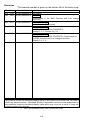
Revisions
*The manual number is given on the bottom left of the back cover.
Print Date
*Manual Number
Revision
Sep., 1999 IB-(NA)-0800059-A First edition
Dec., 1999 IB-(NA)-0800059-B Addition
Conformation to the EMC Directice and Low Voltage
Instruction
Nov., 2001 IB-(NA)-0800059-C Partial correction
Contact adress (Back cover)
Sep., 2007
IB-(NA)-0800059-D
Partial correction
SAFETY PRECAUTION, CONTENTS
Chapter 2, 3, 5, Section 5.2, 5.3
Dec., 2007
IB-(NA)-0800059-E
Partial correction
SAFETY PRECAUTION, CONTENTS, Conformation to
the EMC Directive and Low Voltage Instruction
Chapter 2, 4, 5, 6
This manual confers no industrial property rights or any rights of any other kind, nor does it
confer any patent licenses. Mitsubishi Electric Corporation cannot be held responsible for
any problems involving industrial property rights which may occur as a result of using the
contents noted in this manual.
© 1999 MITSUBISHI ELECTRIC CORPORATION
A-3
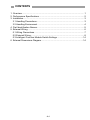
CONTENTS
1. Overview ········································································································1
2. Performance Specifications ···········································································2
3. Installation······································································································3
3.1 Handling Precautions ···············································································3
3.2 Handling Environment ··············································································4
4. Part Identification Names ···············································································5
5. External Wiring·······························································································6
5.1 Wiring Precautions ···················································································7
5.2 External Wiring ·························································································8
5.3 Intelligent Function Module Switch Settings ···········································14
6. External Dimensions Diagram······································································14
A-4
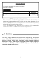
About the Manuals
The following manuals are also related to this product.
Order them if necessary.
Related Manuals
Manual name
Model QD62, QD62E, QD62D High-Speed Counter Module
User's Manual
Manual No.
(Model code)
SH-080036
(13JL95)
Conformation to the EMC Directive and Low Voltage Instruction
When incorporating the Mitsubishi programmable controller into other machinery or
system and keeping compliance with the EMC and low voltage directives, refer to
Chapter 3, "EMC Directives and Low Voltage Directives" of the User's Manual (Hardware)
included with the CPU module or base unit used.
The CE logo is printed on the rating plate on the main body of the programmable
controller that conforms to the EMC directive and low voltage instruction.
1. Overview
This user's manual describes the specifications and the part identification
names of the following modules that are used with the CPU module for
MELSEC-Q series: Model QD62 High-speed Counter Module (hereinafter
referred to as QD62), Model QD62E High-speed Counter Module (hereinafter
referred to as QD62E), and Model QD62D High-speed Counter Module
(Hereinafter referred to as QD62D).
1
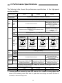
2. Performance Specifications
The following table shows the performance specifications of the high-speed
counter modules:
Model
Item
Number of I/O
occupied point
Number of channels
Phase
Count
input
signal
QD62
2 channels
1-phase input, 2-phase input
5/12/24 V DC 2 to 5 mA
200/100/10 kPPS
(Depends on the Intelligent Function Module switch
settings)
Counting
range
Model
Minimum
count
pulse
width
(Duty ratio
50 %)
Comparis
Coincide
on range
nce
Comparis
output
on result
Preset
External
Function
input
start
EIA rated RS-422-A
Differential Line Driver Level
{ AM26LS31 (Texas
Instruments Incorporated) or
equivalent}
500/200/100/10 kPPS
(Depends on the Intelligent
Function Module switch
settings)
32-bit signed binary (-2147483648 to 2147483647)
UP/DOWN Preset counter + Ring counter function
500 kPPS
(QD62D only)
Counter
QD62D
16 points (I/O assignment: Intelligent 16 points)
Signal
level
Counting
speed
(max) *1
QD62E
2
1
200 kPPS
100 kPPS
5
1
(Unit:μs)
(Min. phase
differential for
2-phase input:
0.5μs)
10
2. 5 2. 5
(Unit:μs)
(Min. phase
differential for
2-phase input:
1.25μs)
5
10 kPPS
100
5 (Unit:μs)
(Min. phase
differential for
2-phase input:
2.5μs)
50 50 (Unit:μs)
(Min. phase
differential for
2-phase input:
25μs)
32-bit signed binary
Set value < Count value; Set value = Count value; Set value > Count value
5/12/24 V DC 2-5 mA
(EIA rated RS-422-A
5/12/24 V DC 2 to 5 mA
Differential Line Driver may
be connected)
Transistor (sink type) output Transistor (source type) output Transistor (sink type) output
External Coinciden
2 points/channel 12/24 V DC 2 points/channel 12/24 V DC 2 points/channel 12/24 V DC
output
ce output
0.5A/point; 2A/common
0.1A/point; 0.4A/common
0.5A/point; 2A/common
Applicable
A6CON1 (Soldering type ,straight out); A6CON2 (Solderless type ,straight out);
connectors
A6CON3 (Pressure welding type ,straight out); A6CON4 (Soldering type ,usable for
straight out and diagonal out)
5 V DC internal
0.30 A
0.33 A
0.38 A
current consumption
Weight
0.11 kg
0.11 kg
0.12 kg
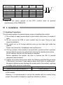
*1: Counting speed is affected by pulse rise and fall time. Possible counting speeds are
shown in the following chart. Note that if a pulse that has a large rise and/or fall time is
counted, a miscount may occur.
2
Counting speed
switch settings
Rise/fall time
t = 0.5 µs or less
t = 1.25 µs or less
t = 2.5 µs or less
t = 25 µs or less
t = 500 µs
500 k
200 k
100 k
Both 1 and 2 phase input
500 kPPS 200 kPPS 100 kPPS
200 kPPS 200 kPPS 100 kPPS
—
100 kPPS 100 kPPS
—
—
10 kPPS
—
—
—
10 k
10 kPPS
10 kPPS
10 kPPS
10 kPPS
500PPS
t
t
Remark
Refer to the user's manual of the CPU module used for general
specifications of the QD62(E/D).
3. Installation
3.1 Handling Precautions
The following explains the precautionary notes on handling the module.
1) Do not drop or apply severe shock to the module case since it is made of
resin.
2) Do not remove the PCB of each module from its case. Doing so may
cause breakdowns.
3) Be careful not to let foreign particles such as wire chips get inside the
module.
These may cause fire, breakdowns and malfunctions.
4) The top surface of the module is covered with a protective film to prevent
foreign objects such as wire chips from entering the module when wiring.
Do not remove this film until the wiring is complete.
Before operating the system, be sure to remove the film to provide
adequate heat ventilation.
5) Tighten the module fixing screw within the following specified torque range.
If the screw is too loose, it may cause a drop, short circuit, or malfunction.
Excessive tightening may damage the screw and/or the module, resulting
in a drop, short circuit or malfunction.
Screw location
Module fixing screws (M3 screws) *1
Tightening torque range
0.36 to 0.48 N⋅m
*1 The module can be easily fixed onto the base unit using the hook at the top
of the module.
However, it is recommended to secure the module with the module fixing
screw if the module is subject to significant vibration or shock.
3
6) To mount the module on the base unit, fully insert the module fixing latch
into the fixing hole in the base unit and press the module using the hole as
a fulcrum.
Improper installation may result in a malfunction or breakdown of the
module, or may cause the module to fall off.
3.2 Installation Environment
For further details, refer to the user's manual for the CPU module used.
4
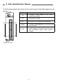
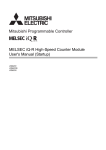
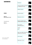
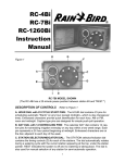
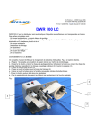
4. Part Identification Names
The following explains the names of the various parts of the high-speed counter
module.
LED name
Description
φA
Lit: Voltage is being applied to the Phase A
pulse input terminal.
φB
Lit: Voltage is being applied to the Phase B
pulse input terminal.
DEC.
B20
FUNC.
FUSE
B01
Lit: Counter is in the process of subtraction.
A20
Lit: Voltage is being applied to the function start
input terminal.
Lit: Voltage is being applied to the external
power supply input terminal while the fuse in
the coincidence signal output section is
broken.
A01
Serial number plate
5
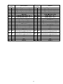
Terminal
number
CH1 CH2
A20 A13
B20 B13
A19 A12
B19 B12
A18 A11
B18 B11
A17 A10
B17 B10
A16 A09
B16 B09
A15 A08
B15 B08
A14 A07
B14 B07
A06
A05
B06
B05
A04
B04
A02
B02
A03
B03
A01
B01
Terminal
number
QD62,QD62E
Signal name
Phase A pulse input 24 V
Phase A pulse input 12 V
Phase A pulse input 5 V
ABCOM
Phase B pulse input 24 V
Phase B pulse input 12 V
Phase B pulse input 5 V
Preset input 24 V
Preset input 12 V
Preset input 5 V
CTRLCOM
Function start input 24 V
Function start input 12 V
Function start input 5 V
EQU1
(Coincidence output point No. 1)
EQU2
(Coincidence output point No. 2)
NC
NC
0V
12/24 V
CH1 CH2
A20 A14
B20 B14
A19 A13
B19 B13
A18 A12
B18 B12
A17 A11
B17 B11
A16 A10
B16 B10
A15 A09
B15 B09
A08 A07
B08 B07
6
A06
A05
B06
B05
A04
B04
A02
B02
A03
B03
A01
B01
QD62D
Signal name
Phase A pulse input
Phase A pulse input
Phase B pulse input
Phase B pulse input
Preset input 24 V
Preset input 12 V
Preset input 5 V
PRSTCOM
Function start input 24 V
Function start input 12 V
Function start input 5 V
FUNCCOM
NC
NC
EQU1
(Coincidence output point No. 1)
EQU2
(Coincidence output point No. 2)
NC
NC
0V
12/24 V
5. External Wiring
5.1 Wiring Precautions
1) Different terminals have been prepared for connection depending on the
voltage of the input signal. Connecting a terminal of incorrect voltage may
result in malfunction or mechanical failure.
2) For 1-phase input, always perform pulse input wiring on the Phase A side.
3) For the QD62 (E/D), count will be performed if pulse status noise is input
and a miscount will result.
4) Provide the following measures against noise for high-speed pulse input:
a) Always use a shielded twisted pair cable and provide grounding.
b) Avoid placing the shielded twisted pair cable parallel to wires that have
large amounts of noise such as power cables or input/output cables.
Place the cable at least 150mm (5.9 inch) from such wires and perform
wiring using the least distance as possible.
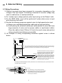
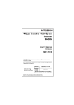
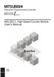
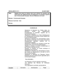
5) An example of wiring incorporating measures against noise is shown
below:
Programmable
controller
QD62 (E/D)
Inverter
Terminal block
Do not enclose solenoids and inductive loads together within the same metal conduit.
If a sufficient distance cannot be secured to isolate ducts and other wires from a highvoltage line, use CVVS or other shielded wire for the high-voltage line.
Provide a clearance
of 150 mm (5.9 inch)
or more from I/O
wires to high voltage
equipment such as
inverters. (Also
exercise caution for
wiring inside the
panel.)
AC
motor
The distance between the encoder and relay box
must be short. Allowing a long distance between
the QD62 (E/D) and the encoder may cause a
Relay box voltage-drop problem. Using a tester or other
measuring device, confirm that the voltage at the
terminal block of the relay box doesn't exceed the
rated voltage when the encoder is in operation or
at standstill. If a substantial voltage drop occurs,
increase the wire size or use a 24 V DC encoder
with minimal current consumption.
Encoder
Carrier
• Grounding the shielded twisted pair cable is performed on the encoder side (relay box). (This example shows
connection with 24 V sink load.
+ 24 V
Current for the encoder
To A
To B
To QD62 (E/D)
To the encoder
0V
A
B
24V
E
E
The shielded wire for the encoder and shielded
twisted pair cable are connected inside the relay box .
If the shielded wire for the encoder is not grounded
inside the encoder, ground it in the relay box, as
indicated by the dotted line.
7
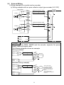
5.2 External Wiring
1) Wiring example of a module and an encoder
a) Wiring example with an open collector output type encoder (24 V DC)
QD62,QD62E
24 V
A20 (A13)
Shielded twisted pair cable
12 V
B20(B13)
Phase A
Encoder
OUT
+24 V
Shield
5V
A19(A12)
E
ABCOM
B19(B12)
24 V
A18(A11)
Shielded twisted pair cable
OUT
12 V
B18(B11)
Phase B
Shield
5V
A17(A10)
External
power
supply
+24 V
E
+24 V
24 V DC
0V
0V
POINT
When wiring the QD62, QD62E and the encoder, separate the power
supply cable and signal cable.
The following diagram shows an example.
[Wiring example]
OUT
QD62(E) 24 V
Phase ABCOM
A
+24 V
0V
Encoder
E
External 24 V DC
power
0V
supply
[Incorrect wiring example]
OUT
QD62(E) 24 V
Phase ABCOM
A
+24 V
0V
E
External 24 V DC
power
0V
supply
8
Encoder
The current flows
through the shielded
twisted pair cable in
the same direction, so
there is no cancelling
effect.
This makes it more
prone to electromagnetic
induction.
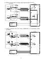
b) Wiring example with a voltage output type encoder (5 V DC)
QD62,QD62E
Encoder
24 V
A20(A13)
12 V
B20(B13)
Phase A
5V
A19(A12)
Shielded twisted pair cable
OUT
GND
Shield
ABCOM
B19(B12)
E
24 V
A18(A11)
12 V
B18(B11)
Phase B
5V
A17(A10)
Shielded twisted pair cable
GND
Shield
External
power
supply
OUT
E
+5 V
5 V DC
0V
0V
c) Wiring example with line driver (AM26LS31 or equivalent) pulse
generator
QD62D
Encoder
A
A20(A14)
Phase A
Shielded twisted pair cable
A
B20(B14)
A
A
Shield
E
B
A19(A13)
Phase B
Shielded twisted pair cable
B
B19(B13)
B
B
Shield
E
External
power
supply
VCC
VCC
0V
0V
9
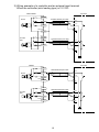
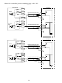
2) Wiring example of a controller and an external input terminal
When the controller (sink loading type) is 12 V DC:
QD62,QD62E
Controller
24 V
B17(B10)
Preset
12 V
A16(A09)
Shielded twisted pair cable
5V
B16(B09)
Shield
OUT
+12 V
E
CTRLCOM
A15(A08)
24 V
B15(B08)
Function
start
12 V
A14(A07)
Shielded twisted pair cable
5V
B14(B07)
Shield
OUT
+12 V
E
12 V DC
QD62D
Controller
24 V
A18(A12)
Preset
12 V
B18(B12)
Shielded twisted pair cable
5V
A17(A11)
Shield
PRSTCOM
B17(B11)
OUT
+12V
E
24 V
A16(A10)
Function
start
12 V
B16( B10)
Shielded twisted pair cable
5V
A15(A09)
Shield
FUNCCOM
B15(B09)
OUT
+12 V
E
12 V DC
10
When the controller (source loading type) is 5 V DC:
QD62,QD62E
Controller
24 V
B17(B10)
12 V
A16(A09)
Preset
5V
B16(B09)
Shielded twisted pair cable
OUT
GND
Shield
CTRLCOM
A15(A08)
E
24 V
B15(B08)
12 V
A14(A07)
Function
start
5V
B14(B07)
Shielded twisted pair cable
OUT
GND
Shield
E
5 V DC
QD62D
Contrller
24 V
A18(A12)
Preset
12 V
B18(B12)
5V
A17(A11)
Shielded twisted pair cable
OUT
GND
PRSTCOM
B17(B11)
Shield
E
24 V
A16(A10)
Function
start
12 V
B16(B10)
5V
A15(A09)
Shielded twisted pair cable
OUT
GND
FUNCCOM
B15(B09)
Shield
E
5 V DC
11
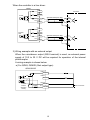
When the controller is a line driver:
QD62D
24 V
A18(A12)
Controller
12 V
B18(B12)
Preset
5V
A17(A11)
Shielded twisted pair cable
PRSTCOM
B17(B11)
OUT
OUT
Shield
E
24 V
A16(A10)
12 V
B16(B10)
Function
start
5V
A15(A09)
Shielded twisted pair cable
FUNCCOM
B15(B09)
OUT
OUT
Shield
E
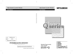
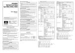
3) Wiring example with an external output
When the coincidence output (EQU terminal) is used, an external power
supply of 10.2 to 30 V DC will be required for operation of the internal
photocoupler.
A wiring example is shown below.
a) For QD62, QD62D (Sink output type)
QD62,QD62D
EQU1
A06(A05)
EQU2
B06(B05)
To fuse
broken
detection
circuitry
FUSE
12/24 V
B02,B01
0V
A02,A01
12
L
L
10.2 to 30 V DC
b) For QD62E (Source output type)
QD62E
EQU1
A06(A05)
EQU2
B06(B05)
FUSE
To fuse
broken
detection
circuitry
12/24 V
B02,B01
0V
A02,A01
13
L
L
10.2 to 30 V DC
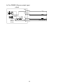
5.3 Intelligent Function Module Switch Settings
The intelligent function module switch settings are performed using the I/O
assignment settings of the GX Developer.
0
Setting item
Pulse input mode
0: 1 phase multiple of 1
1: 1 phase multiple of 2
2: CW/CCW
3: 2 phase multiple of 1
4: 2 phase multiple of 2
5: 2 phase multiple of 4
Counting speed setting
0: 10 kPPS
1: 100 kPPS
2: 200 kPPS
3: 500 kPPS
(only for the QD62D)
Counter type
0: Linear counter
1: Ring counter
Reserved
Reserved
Reserved
H
Switch 1
(for Channel 1)
Switch 2
(for Channel 2)
Switch 3
Switch 4
Switch 5
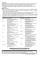
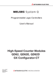
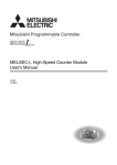
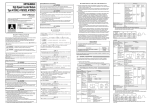
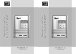
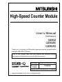
46 (1.81)
90 (3.54)
4 (0.16)
98 (3.86)
6. External Dimensions Diagram
23 (0.91)
27.4 (1.08)
Unit:mm(inch)
14
Warranty
Mitsubishi will not be held liable for damage caused by factors found not to be the cause of
Mitsubishi; machine damage or lost profits caused by faults in the Mitsubishi products;
damage, secondary damage, accident compensation caused by special factors
unpredictable by Mitsubishi; damages to products other than Mitsubishi products; and to
other duties.
For safe use
y This product has been manufactured as a general-purpose part for general industries,
and has not been designed or manufactured to be incorporated in a device or system
used in purposes related to human life.
y Before using the product for special purposes such as nuclear power, electric power,
aerospace, medicine or passenger movement vehicles, consult with Mitsubishi.
y This product has been manufactured under strict quality control. However, when installing
the product where major accidents or losses could occur if the product fails, install
appropriate backup or failsafe functions in the system.
Country/Region Sales office/Tel
Country/Region Sales office/Tel
Hong Kong
Mitsubishi Electric Automation
U.S.A
Mitsubishi Electric Automation Inc.
(Hong Kong) Ltd.
500 Corporate Woods Parkway Vernon
10th Floor, Manulife Tower, 169 Electric
Hills, IL 60061, U.S.A.
Road, North Point, Hong Kong
Tel : +1-847-478-2100
Tel : +852-2887-8870
Brazil
MELCO-TEC Rep. Com.e Assessoria
China
Mitsubishi
Electric Automation
Tecnica Ltda.
(Shanghai) Ltd.
Rua Correia Dias, 184,
4/F Zhi Fu Plazz, No.80 Xin Chang Road,
Edificio Paraiso Trade Center-8 andar
Shanghai 200003, China
Paraiso, Sao Paulo, SP Brazil
Tel : +86-21-6120-0808
Tel : +55-11-5908-8331
Taiwan
Setsuyo Enterprise Co., Ltd.
Germany
Mitsubishi Electric Europe B.V. German
6F No.105 Wu-Kung 3rd.Rd, Wu-Ku
Branch
Hsiang, Taipei Hsine, Taiwan
Gothaer Strasse 8 D-40880 Ratingen,
Tel : +886-2-2299-2499
GERMANY
Korea
Mitsubishi Electric Automation Korea
Co., Ltd.
Tel : +49-2102-486-0
1480-6, Gayang-dong, Gangseo-ku
U.K
Mitsubishi Electric Europe B.V. UK
Seoul 157-200, Korea
Branch
Tel : +82-2-3660-9552
Travellers Lane, Hatfield, Hertfordshire.,
Singapore
Mitsubishi Electric Asia Pte, Ltd.
AL10 8XB, U.K.
307 Alexandra Road #05-01/02,
Tel : +44-1707-276100
Mitsubishi Electric Building,
Italy
Mitsubishi Electric Europe B.V. Italian
Singapore 159943
Branch
Tel : +65-6470-2460
Centro Dir. Colleoni, Pal. Perseo-Ingr.2
Thailand
Mitsubishi Electric Automation (Thailand)
Via Paracelso 12, I-20041 Agrate Brianza.,
Co., Ltd.
Milano, Italy
Bang-Chan Industrial Estate No.111
Tel : +39-039-60531
Moo 4, Serithai Rd, T.Kannayao,
Spain
Mitsubishi Electric Europe B.V. Spanish
A.Kannayao, Bangkok 10230 Thailand
Branch
Tel : +66-2-517-1326
Indonesia
P.T. Autoteknindo Sumber Makmur
Carretera de Rubi 76-80,
Muara Karang Selatan, Block A/Utara
E-08190 Sant Cugat del Valles,
No.1 Kav. No.11 Kawasan Industri
Barcelona, Spain
Pergudangan Jakarta - Utara 14440,
Tel : +34-93-565-3131
P.O.Box 5045 Jakarta, 11050 Indonesia
France
Mitsubishi Electric Europe B.V. French
Tel : +62-21-6630833
Branch
India
Messung Systems Pvt, Ltd.
25, Boulevard des Bouvets, F-92741
Electronic Sadan NO:III Unit No15,
Nanterre Cedex, France
M.I.D.C Bhosari, Pune-411026, India
TEL: +33-1-5568-5568
Tel : +91-20-2712-3130
South Africa
Circuit Breaker Industries Ltd.
Australia
Mitsubishi Electric Australia Pty. Ltd.
Private Bag 2016, ZA-1600 Isando,
348 Victoria Road, Rydalmere,
South Africa
N.S.W 2116, Australia
Tel : +27-11-928-2000
Tel : +61-2-9684-7777
HEAD OFFICE : TOKYO BUILDING, 2-7-3 MARUNOUCHI, CHIYODA-KU, TOKYO 100-8310, JAPAN
NAGOYA WORKS : 1-14, YADA-MINAMI 5-CHOME, HIGASHI-KU, NAGOYA, JAPAN
When exported from Japan, this manual does not require application to the Ministry
of Economy, Trade and Industry for service transaction permission.
Specifications subject to change without notice.
Printed in Japan on recycled paper.