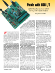
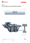
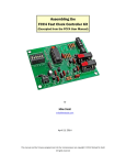
1
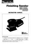
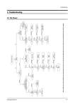
CIRCUIT MONKEY
RS232LS
RS-232 to 3V/5V Logic Level Translator
User Manual
5/19/2012
This printed circuit assembly will translate UART logic signals from 3V to 5.5V to EIA/TIA-232 and
V.28/V.24 specification. Output transmit levels are ±5V and receive levels can up to ±20V. Maximum
data rate is 460kbps. It requires 3V to 5.5V to operate at 3mA no load and 12mA with a maximum 3KΩ
load. The board will translate both transmit and receive signals plus hardware handshake CTS/RTS
signals. It can be a RS232 DTE (data terminal equipment) like a computer using a DE-9 pin male
connector or a RS232 DCE (Data circuit-terminating equipment) like a modem using a DE-9 pin female
connector. It can also snoop both transmit and receive as an inline device. It has individual LEDs to
monitor activity on the RS232 transmit and receive lines.
RS232 Driver
U1
0.1uF
4
C5
5
0.1uF
UART0
1
LVCTS
LVTXD
11
2
LVRTS
LVRTS
10
3
LVRXD
LVRXD
12
4
LVTXD
LVCTS
9
CTS
RTS
RX
TX
5
15
VCC
3.3V/5V
6
GND
C1
C1+
VCC
Voltage Doubler
C1V+
C2+
VVoltage Inverter
C2T1in
T1out
T2in
T2out
R1out
R1in
R2out
R2in
16
GND
C3
2
6
0.1uF
C4
0.1uF
GND
GND
0.1uF
RX
1
2
2
14
TX
3
4
3
7
RTS
5
6
7
13
CTS
7
8
8
8
TX
9
10
2
RX
11
12
3
CTS
13
14
7
RTS
15
16
8
GND
ICL3232
J1
DTE
3
1
DCE
1
C2
J2
R1
10K
1
LVRXD
2
LVTXD
3
VCC
R2
150
DSR
3
GND
GND
CD
2
DTR
4
DSR
5
R3
150
R4
10K
RX
RI
J3
DTE (Computer)
DCE (Modem)
TX
J4
3.3V/5V
D1
J6
D2
Q1
2N7000
GND
GND
R5
1M
Q2
2N7000
GND
R6
1M
CD
DSR
RXD
RTS
TXD
CTS
DTR
RI
GND
SD
DCE
TXD
CTS
RXD
RTS
DTE
RI
DE9 Male
GND
GND
J5
1
6
2
7
3
8
4
9
5
4
GND
GND
GND
GND
GND
Figure 1 Schematic RS232 to 3V/5V Translator
RS232 to 3V/5V Logic Level Translator Kit – ©2012 Ferndale Labs
1
6
2
7
3
8
4
9
5
DE9 Female
GND
Building the kit
This is a simple soldering project but assumes some soldering experience. To find out more, do a search
on “how to solder electronics” using your favorite search engine. A few sites such as aaroncake,
ElectronixExpress, and Science Buddies have information on how to solder. Equipment needed is:
a)
b)
c)
d)
e)
Soldering iron intended for electronic assembly.
Solder can be leaded or lead free; however, do not use acid core solder
Wire cutters and needle nose pliers
A clean well lit workspace
A magnifying glass
Verify all parts are available before starting construction. They should match this photograph
although some of the parts may have variations in colors and markings. Read through each of the
assembly steps before doing the work.
Quantity
Designator
Rating
Manufacturer
Part Number
1
5
C1, C2,
C3, C4, C5
0.1uF 50V X7R
Ceramic Radial
Capacitor
Murata
RDER71H104K0K1
C03B
2
2
D1, D2
Orange LED 2V
20mA
Kingbright
WP710A10SEC
3
1
J1
(Optional)
6-pin 2mm
Single Row
Header
Molex
53014-0610
4
1
J2
16-pin 0.1" Dual
Row Header
FCI
68602-116HLF
5
1
J4
DE9 9 pin Male
D-Connector
Amphenol
L717SDE09P
6
1
J5
DE9 9 pin
Female DConnector
Amphenol
L77SDE09S
RS232 to 3V/5V Logic Level Translator Kit – ©2012 Ferndale Labs
Photo
7
1
J6
4-pin 2mm
Single Row
Header
Molex
53014-0410
8
2
Q1, Q2
2N7000 NMOS
FET 60V
200mA TO-92
Fairchild
Semiconductor
2N7000_D26Z
9
2
R1, R4
10K 5% 1/8w
Axial Resistor
Stackpole
CF14JT10K0
10
2
R2, R3
150 5% 1/8w
Axial Resistor
Stackpole
CF18JT150R
11
2
R5, R6
1M 5% 1/8w
Axial Resistor
Stackpole
CF14JT1M00
12
1
U1
ADM3202
RS232 Level
Shifter DIP-16
Analog
Devices
ADM3202ANZ
13
1
Printed Circuit
Board
RS232 to 3V/5V Logic Level Translator Kit – ©2012 Ferndale Labs
Take a look at the Assembly
drawing to the left (Figure 2). Part
placement is indicated by the
reference designator like C1, R2, U1,
J2, etc. Some parts must be put in
oriented correctly. All parts except
for J4 and J5 are mounted on the
top side, that is, the side with the
white silk screen printing.
o
o
o
o Start with the two 10KΩ
resistors (brown-black-orange-gold).
Remove the resistors from the tape
and bend
Figure 2 Assembly Drawing
the
leads
right angle to the body. The resistors can be cut from the tape if you
leave an inch or more of lead from the body. Take a look at the how
the resistor should look from Figure 3. Push the leads through the
holes marked R1 and R4 and while holding the
Figure 3 Resistor lead forming and installation
resistor from the top side bend the leads out
slightly so the resistors don’t fall out. Figure 3
shows R1 placed on the board. Solder the two leads of each resistor and then trim the leads
once it’s soldered as in Figure 4.
In the same manner as the previous step, install the 150Ω resistors at R2 and R3.
In the same manner as the previous step, install the
1MΩ resistors at R5 and R6.
Install the 0.1µF 50V capacitors C1, C2, C3, C4 and C5.
These are not polarized and can be oriented either way.
They install like the resistors except do not require prebending the leads. See Figure 5 to see the resistors and
capacitors installed.
Figure 4 Trimming leads after soldering
Figure 5 Capacitors and Resistors installed
RS232 to 3V/5V Logic Level Translator Kit – ©2012 Ferndale Labs
o
o
Install the IC U1 which is 16 pin DIP package marked as Analog Devices ADM3202 on the
top. This part must be oriented correctly. Look at the IC from the top – there is a notch
at the top with a small circle to the left. Now look at the PC board white marking – there
is a white dot and the U1 marking. The dot on the IC and the dot on PC should be next
to each other. Sometimes the pins on DIP packages are skewed out and it’s difficult getting all
16 pins into the holes. I usually take the part between my fingers
and put it with the side against a flat surface like a table to gently
bend the pins inwards. Observing the correct orientation put the IC
into the 16 pad holes and make sure that all the pins came through
the pads. Now solder two pads that are on diagonal from each
other. (Pin 1 and pin 9 for example). With your fingers pushing
against the part, reflow the solder on both pins so that the part is
U1
o
Install the two FETs Q1 and Q2. These are 2N7000 NMOS FETs and
must be oriented correctly with the board. Notice the semicircle with
a flat face on the PCB artwork. This should match the half-moon
shape of the transistor. The three leads go into the three pads –
make sure that the flat side of the half-moon on the transistor
matches the white printing on the PCB. You can hold the transistor
on one side and bend the outer two wire leads of the transistor to
help hold it in. The pads are close together so use just enough solder to
Figure 6 Installing Transistors
attach the wires and make sure the pads don’t have solder bridge
between them. Trim the leads when soldered.
Install the light emitting diodes (LED) at D1 and D2. These are polarized so pin orientation
is important. Hold the LED up and notice that one lead is longer than the other. Now look
at the white silk screen printing on the board for D1 and D2. There should be a round
circle with two lines coming from the circle with one of the lines longer than the other. Put
the long lead into the hole where the longest line on the silkscreen as depicted in the
figure to the right. Once placed into the correct pads, bend the leads as you did the
transistors and solder the connection. Trim the leads with wire cutters when done.
properly seated on the PC board. Double check that the part is
Figure 7 IC and LED installed
oriented with pin 1 dot next to the PC silkscreen mark. Now
solder the remaining 14 pads. You do not need to trim the leads on the IC. At this stage, the
board should look like Figure 7.
o
Install the white 6-pin 2mm connector at J1 and the white 4-pin 2mm
connector at J6 making sure they are properly oriented. The connectors
have ‘1’ embossed on the side with the two open notches. The ‘1’ should
be installed close to the dot and J1/J6 marking. See Figure 8 for
orientation. Solder the top and bottom pins and while apply
pressure against the connector without touching the pins, reflow
RS232 to 3V/5V Logic Level Translator Kit – ©2012 Ferndale Labs
Figure 8 Connectors installed
o
o
o
solder of the top and bottom pins to allow the part to seat properly on the PC board. Solder the
remaining pins. The pins do not need to be trimmed.
Install 16 pin dual row header at J2. This has 16 pins sticking through a plastic block one side has
longer pins than the other side. The side with the shorter length of pins goes into the board to be
soldered. Solder two diagonal pins, insure the part is seated properly and then solder the remaining
pads. The pins do not need to be trimmed.
Install the 9-pin D male connector at J4 (left edge of the board). The connector will mount on the
edge of the PC Board. The board will sandwich between the two rows of pins coming out of the back
of the connector. The connector has a five pins on top row and four pins on the bottom row. The PC
board has five exposed pads along the top edge of the board
and four exposed pads on the bottom. Orient the connector
next to the PC board so that the five pads match up to the five
pins on the connector. With a gentle see-saw movement slide
the connector onto the PC board and insure the pins are in
the center of the pads. Heat one of the pads and flow solder,
making sure the connector is seated against the PC board and
centered. Solder the remaining seven pads on top and bottom
of the PC board.
Figure 9 Installing the 9-pin D connector
Double check all connections and look for cold solder joints,
solder bridges, bent pins, badly seated parts. This completes the assembly of the RS232 Level
Translator Kit.
RS232 to 3V/5V Logic Level Translator Kit – ©2012 Ferndale Labs
Using the RS232 Translator
Connecting logic UART to RS232LS.
The device you want to level shift will connect to either J1 (6 pin) if using CTS/RTS handshaking or J6 (4
pin) if you aren’t using handshaking. The 6 pin connector mates with the Molex 51004-0600 housing
with six Molex 50011-8000 contacts and 24-30AWG wire. The 4 pin connector mates with the Molex
51004-0400 housing with six Molex 50011-8000 contacts and 24-30AWG wire. These can be purchased
with precrimped pigtails from Circuit Monkey. You canalso
not install the connectors on J1 or J6 and wire directly
between the target and RS232LS.
For the 4-pin connector J6, pin 1 connects to the receive
data input of the target. Pin 2 connects to transmit data
output from target. Pin 3 goes to 3V to 5V power from
target (max 12mA) and pin 4 goes to the ground return.
For the 6-pin connector J1, pin 1 connects to CTS input of
the target. Pin2 connects to RTS output from the target.
Pin 3 goes to the receive data input of the target. Pin 4
connects to transmit data output from target. Pin 5 goes to
3V to 5V power from target (max 12mA) and pin 6 goes to
the ground return.
RS232 to 3V/5V Logic Level Translator Kit – ©2012 Ferndale Labs
Connecting RS232 to the RS232LS
IBM defined RS232 end devices, such as a computer, as Data Terminal Equipment (DTE) and
communication devices like the modem as a Data Circuit Terminating Equipment (DCE). Today, this has
come to mean DTE is the male DE9M on the PC or USB to Serial converter and DCE is what connects to
the PC over RS232 and usually has a female DE9F. The DCE could be a GPS, motor controller, etc.
RS232 connectors originally used DB25, 25 pin D style on the early IBM PC. The ‘B’ in DB25 denoted the
size of the connector. The PC was later changed to the smaller DE9 connector although, from a past
mistake, is often sold as DB9.
DTE
Data Terminal Equipment
DCE
Data Circuit Terminating
Equipment
Female
DB9
Male
DB9
RS232 Cable
The DTE example is a microcontroller that wants to talk to an RS232 device that would normally plug
into a PC male DE9. It requires jumpers on J2 jumper block for no handshake, RTS/CTS handshake used
or handshake looped back. See the below picture for how the jumpers are set.
RS232 Cable
RS232 to 3V/5V Logic Level Translator Kit – ©2012 Ferndale Labs
DTE
Handshake
Loopback
Male
DE9
RTS/CTS
Handshake
Female
DE9
No Handshake
DCE
Data Circuit Terminating
Equipment
For a DCE example, the target connects to the PC or USB to serial converter over RS232 like a modem or
GPS receiver. It requires jumpers on J2 jumper block for no handshake, RTS/CTS handshake used or
handshake looped back. See the below picture for how the jumpers are set.
Handshake
Loopback
RTS/CTS
Handshake
No Handshake
Male
DE9
Female
DE9
RS232 Cable
The serial line can be passively snooped by the target board for either the receive or transmit line.
DTE
Data Terminal Equipment
Male
DB9
Snoop RX from DTE
Female
DB9
Snoop TX from DTE
DCE
Data Circuit Terminating
Equipment
RS232 Cable
RS232 Cable
Female
DB9
RS232 to 3V/5V Logic Level Translator Kit – ©2012 Ferndale Labs
Male
DB9