1
L1 SENSOR
USER MANUAL
By
LMI Technologies Inc.
Date: Oct. 6, 2004
Revision: B
Date: Oct. 6, 2004
Revision: B
PROPRIETARY
This document, submitted in confidence, contains proprietary information that shall not
be reproduced or transferred to other documents or disclosed to others or used for
manufacturing or any other purpose without prior written permission of LMI
Technologies Inc.
LMI Technologies Inc.
1673 Cliveden Ave.
Delta, BC V3M 6V5
Canada
Telephone: 604 636 1011
Fax: 604 516 8368
www.lmint.com
Trademarks and Restrictions
DynaVision is a registered trademark of LMI
Technologies Inc.
This product is designated for use solely as a
component and as such it does not comply with
the standards relating to laser products specified in
U.S. FDA CFR Title 21 Part 1040.
Windows NT, Windows 2000 and Windows
XP are registered trademarks of Microsoft
Corporation.
No part of this publication may be copied,
photocopied, reproduced, transmitted, transcribed,
or reduced to any electronic medium or machine
readable form without prior written consent of LMI
Technologies Inc.
Printed in Canada.
Table of Contents
1.
INTRODUCTION ..................................................................................................... 6
1.1
General Description .......................................................................................... 6
1.2
Sensor Configuration....................................................................................... 6
1.3
Sensor Output ................................................................................................. 7
1.4
Performance ..................................................................................................... 8
2. COMPONENT OVERVIEW ................................................................................... 10
2.1
L1 sensor Head .............................................................................................. 10
2.2
Host Interface ................................................................................................. 10
2.3
L1 Scanner Frame (not supplied) ................................................................... 11
2.4
Cable Assemblies (not supplied) .................................................................... 11
3. SAFETY CONSIDERATIONS................................................................................ 12
3.1
Laser Safety ................................................................................................... 12
3.2
Laser Safety Requirements ............................................................................ 14
3.2.1
Laser Emission Warning Indicators ......................................................... 14
3.2.2
Beam Attenuator ..................................................................................... 14
4. SPECIFCATIONS .................................................................................................. 15
4.1
L1 sensor Head .............................................................................................. 15
4.1.1
Mechanical .............................................................................................. 15
4.1.2
Electrical .................................................................................................. 15
4.1.3
Environmental:......................................................................................... 15
4.1.4
Optical (Laser): ........................................................................................ 15
4.2
Host Interface: TAXI_IP_Rx daughter card..................................................... 15
4.2.1
Mechanical: ............................................................................................. 15
4.2.2
Electrical: ................................................................................................. 16
5. SETUP AND OPERATION OF YOUR L1 SENSOR .............................................. 17
5.1
Install the Host Interface ................................................................................. 17
5.1.1
Remove the Host Computer Case........................................................... 17
5.1.2
Inspect the Host Interface assembly........................................................ 17
5.1.3
Connect the sensor head to the Host Interface ....................................... 17
5.1.4
Install the Host Interface assembly into the host computer ..................... 17
5.1.5
Replace the host computer case ............................................................. 17
5.2
Install LMI.SYS Device Driver ......................................................................... 18
5.3
Test Components ........................................................................................... 18
5.3.1
Test sensors ............................................................................................ 18
5.3.2
Test Host Interface .................................................................................. 18
5.4
Mount and Align the sensor Heads................................................................. 19
5.5
Connect the sensor s to the Host Computer................................................... 19
5.6
Calibrate the Scanner System ........................................................................ 20
6. MAINTENANCE AND SERVICING ........................................................................ 21
6.1
Recommended Preventive Maintenance Procedures..................................... 21
6.2
Servicing......................................................................................................... 21
APPENDIX A:
DynaVision® Taxi Interface ............................................................... 22
A.1 Overview......................................................................................................... 23
A.2 Physical Interface ........................................................................................... 23
A.3 Data Packet Structure .................................................................................... 23
A.4 Taxi Interface Library ...................................................................................... 24
A.5 Description of Library Functions ..................................................................... 24
Constants........................................................................................................... 25
Function Return Codes ...................................................................................... 25
Type Definitions ................................................................................................. 26
lxn_GetVersion .................................................................................................. 26
lxn_GetVersionString ......................................................................................... 26
lxn_Init................................................................................................................ 27
lxn_Terminate .................................................................................................... 27
lxn_SetTimeout .................................................................................................. 27
lxn_GetNumHeads............................................................................................. 28
lxn_GetData ....................................................................................................... 28
lxn_GetYCoord................................................................................................... 29
lxn_GetDiags ..................................................................................................... 29
lxn_GetDataAndDiags........................................................................................ 30
lxn_GetAllData ................................................................................................... 31
lxn_GetNumEncoders ........................................................................................ 32
lxn_InitEncoder .................................................................................................. 32
lxn_GetEncoderCount........................................................................................ 33
lxn_SetEncoderCount ........................................................................................ 33
lxn_EncoderCountDirection ............................................................................... 33
lxn_SetEncoderRes ........................................................................................... 34
A.6 Writing a Host Application .............................................................................. 34
APPENDIX B:
Calibrate DLL User Guide ................................................................ 37
B.1 Overview......................................................................................................... 38
B.1.1
sensor Coordinate Frame ....................................................................... 38
B.1.2
Global Coordinate Frame ........................................................................ 38
B.2 The Calibrate DLL API.................................................................................... 39
B.3 Type Definitions.............................................................................................. 40
B.4 Error Codes .................................................................................................... 40
B.5 Example of Using the Calibrate DLL API........................................................ 41
B.6 Calibration Object File .................................................................................... 42
B.7 Calibration Object File Format ........................................................................ 42
APPENDIX C:
Designing a Line Scanning System.................................................. 44
C.1 Overview......................................................................................................... 45
C.2 Head Number and Placement ........................................................................ 45
C.3 Building a Scanner Frame .............................................................................. 46
C.4 Ambient Light Considerations:........................................................................ 47
Material Transport System ........................................................................................ 48
C.5 Encoder Device .............................................................................................. 48
C.6 Host Computer ............................................................................................... 48
C.7 Power Supplies............................................................................................... 49
C.8 Cable Assemblies ........................................................................................... 49
C.9 Host Application.............................................................................................. 49
APPENDIX D:
Cable Specifications......................................................................... 51
D.1 Connector Overview ....................................................................................... 52
D.2 Multi-pin Military Connector............................................................................. 52
D.3 Cable Recommendations ............................................................................... 53
D.4 Fiber Optic Connector..................................................................................... 53
D.5 Optical Fiber ................................................................................................... 53
D.6 Encoder Cable................................................................................................ 53
APPENDIX E:
L-Series Diagnostic Program............................................................ 56
E.1 Introduction..................................................................................................... 57
APPENDIX F:
Modes of Operation.......................................................................... 58
F.1
Sensor modes ................................................................................................ 59
APPENDIX G:
RS-485 Serial Interface .................................................................... 62
Type Definitions ................................................................................................. 65
lxs_GetLibraryVersion........................................................................................ 66
lxs_CreateSerialChannel ................................................................................... 66
lxs_DestroySerialChannel .................................................................................. 67
lxs_OpenSerialChannel ..................................................................................... 67
lxs_CloseSerialChannel ..................................................................................... 67
lxs_SetSerialBusAddress................................................................................... 68
lxs_GetSerialBusAddress .................................................................................. 68
lxs_GetDspVersion ............................................................................................ 68
lxs_Resetsensor................................................................................................. 69
lxs_SetGreyscaleOn .......................................................................................... 69
lxs_SetGreyscaleOff .......................................................................................... 69
lxs_GetSyncInfo................................................................................................. 69
lxs_SetSyncMode .............................................................................................. 70
lxs_WriteSyncMode ........................................................................................... 70
lxs_WriteSerialBusAddress................................................................................ 70
lxs_GetLastError ................................................................................................ 71
L1 User Manual
LMI Technologies Inc.
1. INTRODUCTION
1.1
General Description
®
The DynaVision L1 sensor is a high performance line profiling sensor which can be
used in a wide variety of applications including the profiling of logs, boards, and other
diffuse, or nearly diffuse, surfaces. The L1 sensor is particularly suited to the profiling
of long extruded shapes.
There are currently three models of L1 sensor s available. They are distinguished by
their measurement region and y-axis sampling resolution:
L1-16-20-24:
This is the "standard" L1 sensor. It has a
measurement region extending from 16”to
36”and a 24" field of view (FOV) at 36"
(equivalent to an angular field of view of
36°). Its y-axis sampling resolution is 1/8".
L1-16-6-15:
This is a higher resolution L1 sensor with a
reduced operating range.
It has a
measurement region extending from 16”to
22”and a 15" FOV at 22" (equivalent to an
angular field of view of 39°). Its y-axis
sampling resolution is 1/16".
L1-16-20-15:
This is an intermediate version of the L1
sensor.
It has a measurement region
extending from 16”to 36”and a 15" FOV at
36" (equivalent to an angular field of view
of 22°). Its y-axis sampling resolution is
1/16".
Multiple L1 sensor s can be combined to measure larger objects that exceed the field of
view (FOV) of a single sensor . An array of L1 sensor s can be used to surround
objects and provide complete three-dimensional (3D) scans.
The L1 sensor is assembled entirely from solid-state components housed in a rugged,
sealed enclosure. Range measurement makes use of the latest laser triangulation
technology by projecting a laser line onto the surface of the object being measured.
The CCD array housed in the sensor detects the laser energy reflected from the object.
The sensor incorporates a processor per head approach to data processing using
high-speed, embedded computers.
1.2
Sensor Configuration
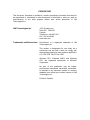
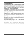
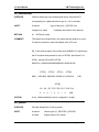
An L1 sensor is comprised of the following elements as shown in Figure 1.
An L1 sensor head
Host interface (high-speed TAXI / Fiber-optic)
Host computer (not supplied)
Page 6 of 71
L1 User Manual
LMI Technologies Inc.
Data is acquired by the sensor head and transmitted to the host computer over the
high-speed TAXI data link to the host interface in the host computer.
Commands can be sent to the sensor head over the RS-485 serial interface although
this is not mandatory. The serial interface can also be used for diagnostics. The
Grayscale Viewer utility requires the serial interface.
Additionally, multiple sensors may be synchronized and multiplexed by daisy chaining
L1 Sensor
Head
Taxi Data Link
Serial interface
Host
Computer
Host Interface
Figure 1. L1 Sensor Configuration
sync lines between sensors and selecting an appropriate mode for each sensor. For
more information, see Appendix G: Modes of Operation.
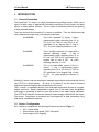
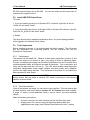
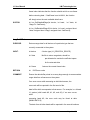
L1
Sensor
Object Transport
Laser fan
Encoder or
similar device
Objects being
scanned
Figure 2. Typical Profile Scanning Application of L1 Sensor
In most applications the object to be scanned is moved underneath the L1 sensor
(applications with the sensor moving are also possible) and an encoder or similar
device is used to generate a third (Z) axis as indicated in Figure 2.
1.3
Sensor Output
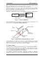
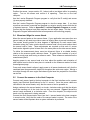
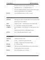
The output of the L1 sensor is a stream of encoded (X,Y) values as shown in Figure 3.
The X-coordinates are explicit values in the data stream. The Y-coordinate of a given
X-value is determined by its position in the profile. For further details on the packet
®
structure, see Appendix A: DynaVision Taxi Interface.
For Windows NT/2000/XP environments, DynaVision® provides an Application
Programming Interface (Host Library) which encapsulates this protocol and provides
Page 7 of 71
L1 User Manual
LMI Technologies Inc.
th
Yk = (k * deltay) + y0
k position in stream
Xk-1
value
Xk
value
Xk+1
value
Figure 3. L1 Sensor output is a stream of encoded (x,y) values
simple call interfaces for data acquisition and sensor
DynaVision® Taxi Interface for further information.
1.4
control.
See Appendix A:
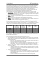
Performance
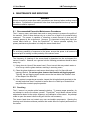
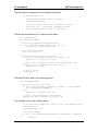
The ultimate performance of a scanning system employing L1 sensor s will depend on
the actual number and configuration of the sensor s, including their location and
orientation relative to the objects being profiled. The performance numbers quoted
here (Table 1) are based on static calibration of the L1 sensor using good diffuse
targets. Performance in actual industrial settings may differ from the results quoted
here. Note that the measurement range is determined relative to the face of the sensor
as shown in Figure 4.
L1-16-20-24 (125)
Operating
Range
Standoff
Field of View
(at range)
Field of View
Scan Rate
Resolution
Accuracy
L1-16-6-15
L1-16-20-15
20" (508mm)
6" (152mm)
20" (508mm)
16" (406mm)
24" (610mm) @ 36"
(914mm)
36°
60 profiles/sec
X-axis: 0.010"
(0.25mm)
Y-axis: 1/8" (3.2mm)
X-axis: ± 0.020 0.060" (0.5-1.5mm)
over the range
Y-axis: ±0.125"
(3.2mm)
16" (406mm)
15" (381mm) @ 22"
(558mm)
39°
60 profiles/sec
X-axis: 0.005"
(0.15mm)
Y-axis: 1/16" (1.6mm)
X-axis: ±0.010 - 0.025"
(0.25-0.65mm) over the
range
Y-axis: ±0.063"
(1.6mm)
16" (406mm)
15" (381mm) @ 36"
(914mm)
22°
60 profiles/sec
X-axis: 0.010" (0.25mm)
Y-axis: 1/16" (1.6mm)
X-axis: ±0.015 - 0.050"
(0.5-1.5mm) over the
range
Y-axis: ±0.063" (1.6mm)
Table 1. L1 sensor Performance
Page 8 of 71
L1 User Manual
LMI Technologies Inc.
Sensor Y Axis
Standoff
Range
(0,0)
Sensor X Axis
L1 Sensor
Measurement Region
Figure 4. Measurement Region
Page 9 of 71
L1 User Manual
LMI Technologies Inc.
2. COMPONENT OVERVIEW
2.1
L1 sensor Head
The L1 sensor head is a high performance laser line sensor based on the triangulation
principle. It is illustrated in Figure 5. It forms the sensing component of the L1 system.
Typical L1 sensor systems employ from one to six L1 sensors depending on the
desired spatial resolution and operating range.
LCD Graphics Display
Camera
Window
Laser
Window
Figure 5. L1 Sensor Head
The L1 sensor head uses a Class IIIB laser device with custom optics to generate a line
profile that is projected onto the object to be scanned. The laser line is imaged using
an internal CCD camera, and the data from the camera is processed into local sensor
coordinates by an onboard signal processor. Output of the L1 sensor head is a stream
of (X,Y) coordinates in the local reference frame of the sensor . L1 sensor s are
calibrated at the factory, and under normal operation do not require subsequent recalibration.
Data from each L1 sensor head is delivered to the Host Interface over a high-speed,
optical-fiber, interface. This provides high noise immunity as well as a data bandwidth
of 100 Mbits/second.
2.2
Host Interface
The Host Interface provides a high-speed, uni-directional, communications interface
between the L1 sensor head, and a user supplied host computer.
Page 10 of 71
L1 User Manual
LMI Technologies Inc.
The L1 Host Interface consists of one or more IndustryPack (IP) carrier boards, and
®
one or more DynaVision TAXI_IP_Rx host-interface daughter boards (one for each L1
sensor). Industry Pack carrier boards can be obtained from GreenSprings and other
®
manufacturers for a variety of host buses including VME, PCI and ISA. DynaVision
currently provides driver support only for GreenSprings ISA/PCI bus IP carriers. An
OEM can, however, use the DynaVision® TAXI_IP_Rx daughter board with any
IndustryPack carrier board and thus develop an interface for VME bus computers.
If you are using the ISA bus carrier cards from GreenSprings, note the following:
Model: PCI-6030 ISA supports up to three (3) DynaVision TAXI_IP_Rx
boards.
Model: PCI-6040 ISA supports up to four (4) DynaVision® TAXI_IP_Rx
boards.
Model: PCI60 supports up to six (6) DynaVision® TAXI_IP_Rx boards.
®
2.3
L1 Scanner Frame (not supplied)
To build an L1 Scanning system it is necessary to provide a suitable support structure
for the L1 sensor heads.
DynaVision® does not provide scanning frames. These can be acquired from a
machinery supplier or systems integrator. General mechanical layout and other design
information of interest to those building a Scanner frame can be found in Appendix C:
Designing a Line Scanning System.
The output of each L1 sensor is in (X, Y) coordinates relative to the sensor face as
shown in Figure 3. In many applications it is desirable to obtain the output relative to
some global frame of reference. This will require some form of system calibration so
that the each sensor’
s location and orientation is known in the selected global frame of
reference. Further details on how to design a calibration object and calibration program
can be found in Appendix B: Calibrate DLL User Guide.
2.4
Cable Assemblies (not supplied)
Two types of cables are required to connect and integrate the components of an L1
sensor. These cables are:
Fiber-optics cable. One from each L1 sensor head to host computer.
Multi-wire cable with AMP military connector. One from each L1 sensor to
power supply. Optionally, this cable can include an RS-485 serial interface
between the L1 sensor s and the host computer.
DynaVision® does not normally supply cables. Test cable sets are typically shipped
with a single L1 sensor order, or can be ordered as separate components.
Specifications for the cables can be found in Appendix D: Cable Specifications.
Page 11 of 71
L1 User Manual
LMI Technologies Inc.
3. SAFETY CONSIDERATIONS
3.1
Laser Safety
The L1 sensor uses lasers for measuring ranges. This requires that specific safety
precautions be taken when servicing the equipment.
Caution!
Use of controls or adjustments, or performance of procedures other than those
specified herein may result in hazardous radiation exposure.
Warning!
Do Not look directly into the laser beam.
Page 12 of 71
L1 User Manual
LMI Technologies Inc.
In accordance with the U.S. Department of Health and Human Services standards
under the Radiation Control for Health and Safety Act of 1968, the following safety
labels are affixed to each individual SENSOR head:
Location of the labels on each individual SENSOR head is indicated in the illustration
below:
Laser radiation is
emitted from this
aperture
AVOID E XPOSURE
PEAK POWER <5 mW
WAVELENGTH 600-710nM
CLASS I IIa LASER PRODUCT
Aperture Label
MARCH 1997
7088 Venture Street Delt a, B. C. CAN ADA
DANGER
LASER RADI ATION
AVOID DIRECT EYE EXPOSURE
Manufactured
DYNAMIC CONTROL SYSTEMS
DynaVision
This productis designated for use solely as a component
and as such it does not comply with the standards
relating to laser products specified in 21 CFR:
Subchapter J.
Identification / Certification Label
Warning Label
1) Operator's and maintenance personnel should be aware of the potentially
dangerous laser radiation and the precautions required.
2) Always wear proper laser safety glasses if there is a chance of being exposed to
the lasers.
3) Never intentionally look into the laser beam! Even when wearing laser safety
glasses, damage to the eyes can result. One will not be able to feel the damage
when the eyes are exposed to the lasers.
4) When servicing the DynaVision® L1 sensor, the power to the sensor should be
disconnected so that the LCD panel on the face of the sensor is OFF.
Page 13 of 71
L1 User Manual
3.2
LMI Technologies Inc.
Laser Safety Requirements
For systems that will be sold or used in the United States, the Department of Health
and Human Services specify that a number of laser safety requirements be maintained.
Full details of these requirements are specified in the booklet “
Regulations for the
Administration and Enforcement of the Radiation Control for Health and Safety Act of
1968”
: HHS Publication FDA 88-8035. This publication can be obtained directly from
the FDA. LMI Technologies Inc. has filed a report with the FDA to assist OEMs in
achieving certification of their own applications. These reports can be referenced by
their accession number, which will be provided upon request.
It is recommended that the information packet be obtained from the FDA for full details
on what the OEM requires to meet FDA certification. However, the following
paragraphs outline areas that are not covered by LMI Technologies Inc. submission
and need to be addressed by the OEM.
3.2.1 Laser Emission Warning Indicators
As specified by the U.S. Department of Health and Human Services under the
Radiation Control for Health and Safety Act of 1968, it is required that the controls
which operate the sensors incorporate a visible or audible signal when the lasers of the
sensors are active.
Typically this consists of a warning lamp which is illuminated when power is supplied to
the sensor. If the sensors are mounted some distance from the controls it is
recommended that warning indicators be placed at each location. When mounting the
warning indicator it is also important not to mount it in a location that would require
human exposure to the laser emissions.
Additionally, CDRH standards require that the indicator be clearly visible through
protective eyewear designed specifically for the wavelengths of the emitted laser
radiation.
3.2.2 Beam Attenuator
CDRH standards also specify that a permanently attached method of preventing
human access to the laser radiation other than switches, power connectors, or key
control must be employed.
Page 14 of 71
L1 User Manual
LMI Technologies Inc.
4. SPECIFCATIONS
4.1
L1 sensor Head
4.1.1 Mechanical
Dimensions:
2.5" x 7.0" x 16.0"
(64mm x 178mm x
407mm)
Weight:
<10lb (<4.5kg)
Mounting:
Three-point mount to eliminate twist of
enclosure, compatible with 5/16" mounting
hardware
4.1.2 Electrical
Power required:
+10VDC to +30VDC (500mA @ 15VDC)
Connectors:
One - ST Fiber-optic connector (for singlemode glass 62.6/125 fiber) - [TAXI data
output]
One - 10 pin male, weatherproof, MIL-C5015 type (ITT Cannon: MS 3102E18-IP) [power supply & serial communications]
4.1.3 Environmental:
Housing:
Sealed,
anodized,
machined
Temperature:
Operating:
Storage:
Humidity:
aluminum,
CNC
0
C to +40
C (32
F to 104
F)
-30
C to +70
C (-22
F to 158
F)
10-95% non condensing @ 40C (104
F)
4.1.4 Optical (Laser):
4.2
Output Power:
>5mW
Wavelength:
600 –710nm
FDA Classification:
Class IIIB
Host Interface: TAXI_IP_Rx daughter card
4.2.1 Mechanical:
Size:
Single-wide IndustryPack form factor
Connectors:
One - ST Fiber-optic connector (for singlemode glass 62.6/125 fiber) - [TAXI data
input]
Two - standard IP headers
Page 15 of 71
L1 User Manual
LMI Technologies Inc.
4.2.2 Electrical:
Power required:
Supplied by IndustryPack carrier card
Page 16 of 71
L1 User Manual
LMI Technologies Inc.
5. SETUP AND OPERATION OF YOUR L1 SENSOR
This section describes the procedures for installing your L1 sensor components.
5.1
Install the Host Interface
To install the host interface do the following.
Remove the host computer cover
Install the TAXI_IP_Rx daughter card on the IP carrier board
Connect the optical fiber to the daughter card
Install the host interface assembly into the host computer
Replace the host computer cover
5.1.1 Remove the Host Computer Case
Switch off the host computer and disconnect it from the AC power.
Undo the screws holding the cover in place and remove the cover so that you have full
access to the computer’
s card cage.
5.1.2 Inspect the Host Interface assembly
®
If you obtained IP carrier boards from DynaVision , the TAXI_IP_Rx daughter cards will
already be installed on them. Otherwise, you will have to mount the daughter cards on
the carrier boards. Before opening the Host Interface package be sure that you have
taken the normal precautions respecting the handling of static sensitive electronic
equipment. It is advisable to use a grounding wrist strap and to perform the installation
on a desk or table fitted with a suitable static mat. Touch the metal part of the power
supply before touching any of the cards or connectors.
Open the Host Interface package and remove the interface assembly (or TAXI_IP_Rx
card if you are supplying the IP carrier board). The TAXI_IP_Rx daughter card should
be firmly seated onto the carrier board.
5.1.3 Connect the sensor head to the Host Interface
Attach the optical fiber from the sensor head to the receiver module on the TAXI_IP_Rx
card. Ensure that the fiber is suitably routed through the computer chassis to allow reinstallation of the cover once the Host Interface assembly is installed. In some
installations, this may be facilitated by running short optical fiber jumpers from the
TAXI_IP_Rx cards to externallyl mounted feed-throughs.
5.1.4 Install the Host Interface assembly into the host computer
Insert the Host Interface assembly firmly into an available expansion slot in the host
computer. In the case of Greensprings ISA based assemblies, two slots required.
5.1.5 Replace the host computer case
Replace the cover on the computer, and re-install the retaining screws. If you are
connecting the serial communications interface to the sensor s, the cable should be
plugged into an RS-485 interface (converters are readily available to convert a standard
Page 17 of 71
L1 User Manual
LMI Technologies Inc.
RS-232 communications port to RS-485). You can now switch the AC power back on
and allow the computer to boot.
5.2
Install LMI.SYS Device Driver
To install:
1. If you are installing the driver to a Windows NT 4.0 machine, right click on the file
"nt4\lmi.inf" and select "Install".
2. If you are installing the driver to a Windows 2000 or Windows XP machine, right click
on the file "2k_xp\lmi.inf" and select "Install".
3. Reboot.
The driver should now be loaded automatically at boot. Any driver loading problems
will be logged in the Windows Event Viewer.
5.3
Test Components
Before installing the sensor s, it is recommended that they be tested. This will confirm
that the components are functioning properly, and will familiarize you with the
®
DynaVision components.
5.3.1 Test sensors
The sensors can be tested first. Observe all laser safety precautions (section 3), and
position the sensor to be tested so that a test object is within its operating region.
Connect a suitable power supply (see Electrical Specifications for the L1 sensor) to the
test/demonstration cable, and connect the cable to the sensor. Turn on the power, and
verify that the laser and the LCD are on. The LCD should display some diagnostics
information (temperatures, power supply voltages, and laser power), and a graphical
profile of the object being scanned. Turn the power to the sensor off, and repeat the
above process for each sensor.
CAUTION!
Always ensure that the power is switched OFF before connecting or disconnecting
cables to a sensor head.
5.3.2 Test Host Interface
Once all the sensors are tested, you can test the Host Interface. This test requires that
the Host Interface, and Host Software (sections 5.1 & 5.2 above) have been installed.
A single L1 sensor is used (additional sensor s can be used if you have additional
cables).
Make the following connections:
Connect a sensor to the Host Interface with the test fiber-optic cable
Supply power to the sensor using the test/demonstration cable and
appropriate power supply (see Electrical Specifications for the L1 sensor)
Page 18 of 71
L1 User Manual
LMI Technologies Inc.
Position the sensor (as per section 5.3.1 above) with a test object within its operating
region. Turn on the sensor and confirm it is operating. Then turn on the host
computer.
Use the L-series Diagnostic Program program to verify that the IP card(s) and sensor
(s) were properly detected.
Use the L-series Diagnostic Program program to view the sensor data. If you have
more than one sensor connected and powered up, select a specific sensor from the list
of detected sensors. Refer to Appendix E: L-series Diagnostic Program as needed.
Confirm that the displayed scan data matches the test object shape. Exit the L-series
Diagnostic Program when satisfied that all components are functioning properly.
5.4
Mount and Align the sensor Heads
Mount the sensor heads on the scanner frame. If your application uses more than one
sensor head you will need to provide a means of aligning them to prevent interference.
The mounts should provide for three degrees of adjustment for each sensor head:
translation along the Z-axis, rotation about the sensor head’
s X-axis, and rotation about
the sensor head’
s Y-axis. These adjustments are required so that each L1 sensor
head can be aligned to place its laser fan in the same plane as the other sensor heads.
To define the measurement plane, mount an alignment fixture in a suitable location
relative to the scanner system reference frame. A typical fixture consists of a set of
three (or more) pegs each having a reference mark. These reference marks define the
measurement plane.
Applying power to one sensor head at a time, adjust the position and orientation of
each sensor head so that its laser plane is centered on the reference marks of at least
three alignment pegs.
Once each sensor head is aligned, apply power to all sensor heads and verify that the
combined laser fans generate a single line throughout the entire scan region. Moving a
test object through the scan region and observing the laser line projected on its surface
can do this.
5.5
Connect the sensor s to the Host Computer
Connect each sensor head to the host computer via the Host Interface and to a power
supply (see Electrical Specifications for the L1 sensor). Once the power cables are
connected to the sensor heads, verify that the sensor s can be powered on.
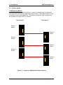
Assign numbers to the sensor heads in a circular, clockwise order such that the objects
would be traveling out of the clock face as they are scanned. Figure 6 shows the
sensor heads numbered in a clockwise order. From this viewpoint, the object would
travel out of the page as it is being scanned.
Connect the fiber communication lines from the L1 sensor heads to the host computer
in numeric order. Verify that the order of the sensor heads is correct. The order of the
sensor heads will be important when a system calibration is performed.
Page 19 of 71
L1 User Manual
5.6
LMI Technologies Inc.
Calibrate the Scanner System
Once all laser fans are co-planar, you can perform a system calibration for the scanner
system. This is required, in order to obtain data from the sensor s in a common
reference frame. The system calibration locates the sensor s relative to the chosen
global reference frame. Your host application can use this calibration information to
translate scan data from local sensor coordinates to your chosen global reference
frame.
You will need to develop a calibration application to perform a scanner system
calibration. A calibration DLL library is provided to support this. It was installed on the
host computer during the L1 sensor software installation. See Appendix B: Calibrate
DLL User Guide for more details.
To perform a system calibration, first mount the calibration fixture in a suitable location.
1
2
Y
L1 Sensors
X
4
3
3
1
4
2
Fiber-Optic
cables
Host Computer
Fig. 6. L1 System Calibration
The calibration target must be placed in the measurement plane such that all laser lines
fall on the target. The exact location of the reference point of the calibration object in
the global reference frame must be known. It may be necessary to survey the
calibration fixture in order to locate it relative to the selected global reference frame.
With the calibration target in place, you can run your calibration application.
Page 20 of 71
L1 User Manual
LMI Technologies Inc.
6. MAINTENANCE AND SERVICING
WARNING!
Always ensure that proper laser safety procedures are observed when working around
the sensor . Performance of procedures other than those specified herein may result in
hazardous radiation exposure.
6.1
Recommended Preventive Maintenance Procedures
The L1 sensor uses a solid-state laser and an array camera to measure the profile of
the material. Both of these devices rely on a clear 'line of sight' to the material being
measured. The sensor is capable of tolerating a certain amount of dust and dirt
normally present in the environment. However, it is important to keep them free from
®
normal debris build up. Since the DynaVision L1 sensor operates optically, the
primary maintenance procedure is to keep the sensor head clean.
NOTE!
To avoid any possibility of exposure to the lasers, ensure that power to all sensors is
removed prior to working in close proximity of the sensor frame.
The frequency of cleaning of the sensor head is dependent on the environment the
sensor is used in. However, as a general rule the following procedures should be done
every day.
1) Using clean air, blow off the sensor head. Do not use air that may contain water or
oil as it may coat the glass windows, resulting in scanning errors.
2) Clean the glass windows on each sensor head using a soft, lint free cloth and
isopropyl alcohol. Do not use glass cleaners that contain anti-fogging agents!
Typically, the anti-fogging agent contains a wax that can distort the camera's view
or the shape of the laser line.
3) If the system incorporates an encoder, inspect the timing belts and sprockets to the
encoder and clean them if required to ensure there is no build up of material that
may affect the encoder's proper operation.
6.2
Servicing
The L1 sensor is a precise optical measuring device. To ensure proper operation, do
®
not attempt to service the sensor yourself. DynaVision must handle several critical
adjustments related to the optics, alignment, and calibration of the sensor. Any attempt
made to open the sensor head housing will void the unit's warranty
The sensor head does not contain any user serviceable components. Opening the
housing could introduce airborne particles that would affect the optical performance of
the sensor.
Page 21 of 71
L1 User Manual
LMI Technologies Inc.
APPENDIX A: DynaVision® Taxi Interface
Page 22 of 71
L1 User Manual
LMI Technologies Inc.
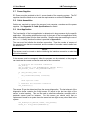
A.1 Overview
Data is transmitted from the L1 sensor head to the associated Host Interface card using
the DynaVision® TAXI Protocol. TAXI is a high-speed, point-to-point, communication
interface developed by Advanced Micro Devices (AMD). In combination with fiber-optic
transmitters and receivers, it provides high noise immunity and a bandwidth of 100
Mbps.
Data transmitted from each L1 sensor head is received in its corresponding
®
DynaVision TAXI_IP_Rx Host Interface where it is stored in a buffer (FIFO) within the
interface. Data is then read from the FIFO by the host computer application. For
®
Windows NT hosts using Greensprings PCI IP carriers, DynaVision provides a host
interface library and device driver which facilitate the transfer of data from the Host
Interface to the host computer's memory. This is described in Appendix A:
®
DynaVision Taxi Interface.
A.2 Physical Interface
The TAXI interface is based on the AMD7968 TAXI Chipset. This supports a high®
speed, point-to-point byte stream. The DynaVision Host Interface card (TAXI_IP_Rx)
receives the byte stream from the TAXI interface and stores the byte values into an
onboard FIFO.
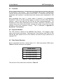
A.3 Data Packet Structure
Data is transmitted from the L1 sensor head in 1K * 16bit word packets (2048 bytes).
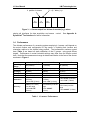
Table A.1 defines the format of the packet.
Header Block
250 Word Data Block
250 Words (reserved)
250 Words (reserved)
250 Words (reserved)
Table A.1. Data Packet Structure
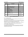
The structure of the header block is defined in Table A.2.
Page 23 of 71
L1 User Manual
LMI Technologies Inc.
Index
0
Description
Packet ID
Units
1111 = L1
4444 = L4
1
Supply voltage (nominally 15 V)
0.1V
2
Internal 5V Regulator supply
0.1V
3
Reserved
4
Case temperature
°C
5
Ambient temperature
°C
6
Data Frame Counter
0 .. 65535
7-21
Reserved
22
Y-axis resolution code
0 or 1008 = 1/8"
1016 = 1/16"
23
Device serial communication ID
Last 2 digits of
Serial Number
Table A.2. Header Block Structure
A.4 Taxi Interface Library
This section describes the Host Application Interface Library (Taxi Interface) for the Lseries sensor s from LMI Technologies Inc.
The host application interface library provides a set of C-language routines to support
data transfer from the Host Interface to host application memory. Support for a
Quadrature encoder card from GreenSprings Ltd is also provided.
The library is provided as a Windows Dynamic Link Library (DLL). This library is
currently available for MS Windows NT 4.0, Windows 2000 and Windows XP.
A.5 Description of Library Functions
This section gives detailed descriptions of the functions provided in the DynaVision®
Host Applications Interface Library. Functions are provided for both L-series sensor
interfacing and encoder interfacing.
Page 24 of 71
L1 User Manual
LMI Technologies Inc.
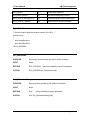
Constants
Constant
Value
Description
NUMDIAGS
24
size of diagnostics array in words
NUMDATA
250
number of data points per laser object
NUML1DATA
250
number of data points per L1 GetData request
NUML4DATA
1000
number of data points per L4 GetData request
MAXATC
4
maximum ATC/PCI carriers in the system
MAXIP
6
maximum IP IO ports
MAX_SENSORS
24
maximum sensors of a particular model
MAX_FRAME
0xFFFF
maximum frame id in lx TAXI frame
FREE_RUNNING_GROUP
24
sync group number for free-running sensors
LX_PACKET_WORDS
1024
number of 16-bit words in an Lx TAXI packet
L1_RANGE_DATA_ID
1111
ID of L1 range data packet
L4_RANGE_DATA_ID
4444
ID of L4 range data packet
L1_GREY_DATA_ID
1113
ID of L1 greyscale data packet
L4_GREY_DATA_ID
4443
ID of L4 greyscale data packet
LX_PACKET_ID_OFFSET
0
offset to packet ID within all Lx packets
L1_DEVICE
0
L1 sensor identification
L4_DEVICE
1
L4 sensor identification
EC_DEVICE
2
Encoder device identification
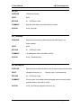
Function Return Codes
Return Code
Value
Description
DCS_SUCCESS
0
successful return
DCS_FAILURE
-1
operation failed
DCS_TIMEOUT
-2
IP host communication timeout
DCS_NO_HOST
-3
IP host not present / failure
DCS_BAD_ARG
-4
one of the input arguments wrong
DCS_NO_TIMER
-5
no peformance timer available
DCS_NODRIVER
-7
device driver not loaded
DCS_NOCAPTURE
-8
data not captured
Page 25 of 71
L1 User Manual
LMI Technologies Inc.
DCS_NOISE
-9
invalid data captured
DCS_BAD_DEVICE
-11
the device specified is invalid
DCS_SYNCH_INCOMPLETE
-12
some groups were not synchronized
DCS_SYNCH_TIMEOUT
-13
data could not be synchronized
Type Definitions
/* Stucture used to hold the revision number of the DLL */
typedef struct
{
short majorRevision;
short minorRevision;
} DCS_VERSION;
lxn_GetVersion
PURPOSE:
Returns the numeric major and minor version numbers.
INPUT:
None
RETURN:
DCS_VERSION
SYNTAX:
DCS_VERSION lxn_GetVersion(void);
//structure containing version information.
lxn_GetVersionString
PURPOSE:
Returns a string containing the version information
INPUT:
None
RETURN:
char*
SYNTAX:
char *lxn_GetVersionString(void);
//string containing version information
Page 26 of 71
L1 User Manual
LMI Technologies Inc.
lxn_Init
PURPOSE:
Initializes the library.
INPUT:
None
RETURN:
int
COMMENT:
Must be called before any other library functions.
SYNTAX:
int lxn_Init(void);
//DCS error code
lxn_Terminate
PURPOSE:
Performs any necessary cleanup when the lxnlib library is no
longer needed.
INPUT:
None
RETURN:
int
COMMENT:
All subsequent calls to this library will fail.
SYNTAX:
int lxn_Terminate(void);
//DCS error code
lxn_SetTimeout
PURPOSE:
Sets the timeout value that will be used in sensor communication calls.
INPUT:
unsigned int timeout_us
RETURN:
int
COMMENT:
If this function is not called before attempting sensor communication,
//timeout value, in microseconds
//DCS error code
a default timeout value will be used.
SYNTAX:
int lxn_SetTimeout(unsigned int timeout_us);
Page 27 of 71
L1 User Manual
LMI Technologies Inc.
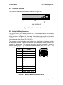
lxn_GetNumHeads
PURPOSE:
Called to obtain the count and physical layout of detected IPs
corresponding to a particular device type (L1, L4 or encoder).
INPUT:
int device
//type of device (L1_DEVICE, etc)
unsigned int *mask
//indicates the location of the devices
RETURN:
int
//DCS error code
COMMENT:
The values the individual bits in the mask indicate whether or not an
IP module is present in each slot aboard each ATC card.
Eg. If the returned value of the mask were 0x8000612, it would imply
that IP modules were present in slot D of ATC#3, slots B and C of
ATC#1, and slots E and B of ATC#0.
8000612h = 00001000000000000000011000010010b
ATC[3]
MSB
ATC[2]
ATC[1]
ATC[0]
00001000 00000000 00000110 00010010
LSB
ATC[0]
XX XX IP-F IP-E IP-D IP-C IP-B IP-A
0
SYNTAX:
0
0
1
0
0
1
0
LSB
int lxn_GetNumHeads(int device, unsigned int *mask);
lxn_GetData
PURPOSE:
Gets the data portion of the Lx packet.
INPUT:
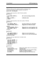
int device
//device type (L1_DEVICE/L4_DEVICE)
int head
//logical index of the sensor
Page 28 of 71
L1 User Manual
LMI Technologies Inc.
int *destination //pre-allocated buffer to return sensor data
RETURN:
int
//DCS error code
COMMENT:
The buffer pointed to by destination should be large enough to hold
(lxn_GetDataSize(device)) elements.
SYNTAX:
int lxn_GetData(int device, int head, int *destination);
int lxn_GetData16(int device, int head, short int *destination);
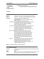
lxn_GetYCoord
PURPOSE:
Returns the y-coordinate associated with each x-coordinate in the
range data for a sensor
INPUT:
int device
//device type (L1_DEVICE/L4_DEVICE)
int head
//logical index of the sensor
int *ycoord
//pre-allocated buffer to return y-coordinates
RETURN:
int
//DCS error code
COMMENT:
The buffer pointed to by ycoord should be large enough to hold
(lxn_GetDataSize(device)) elements.
SYNTAX:
int lxn_GetYCoord(int device, int head, int *ycoord);
int lxn_GetYCoord16(int device, int head, short int *ycoord);
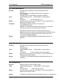
lxn_GetDiags
PURPOSE:
Returns the diagnostic portion of the Lx packet.
INPUT:
int device
//device type (L1_DEVICE/L4_DEVICE)
int head
//logical index of the sensor
int *destination
//pre-allocated buffer to return dianostic data
RETURN:
int
//DCS error code
COMMENT:
The buffer pointed to by destination should be large enough to hold
Page 29 of 71
L1 User Manual
LMI Technologies Inc.
NUMDIAGS elements. Data will be returned in the following format:
Index
0
Description
Units
Packet ID
1111 = L1
4444 = L4
1
Supply voltage (nominally 15 V)
0.1V
2
Internal 5V Regulator supply
0.1V
3
Reserved
4
Case temperature
°C
5
Ambient temperature
°C
6
Data Frame Counter
0 .. 65535
7-21
Reserved
22
Y-axis resolution code
0 or 1008 = 1/8"
1016 = 1/16"
23
SYNTAX:
Device serial communication ID
Last 2 digits of
Serial Number
int lxn_GetDiags(int device, int head, int *destination);
lxn_GetDataAndDiags
PURPOSE:
Returns the data as well as the diagnostic portion of the Lx packet.
INPUT:
int device
//device type (L1_DEVICE/L4_DEVICE)
int head
//logical index of the sensor
unsigned int *data
unsigned int *diags
data
//pre-allocated buffer to return range data
//pre-allocated buffer to return diagnostic
unsigned int *lastFrame //previous frame number
RETURN:
int
//DCS error code
COMMENT:
The intent of the lastFrame parameter is that it be used to obtain
sequential frames from an L-series sensor; passing the previous
Page 30 of 71
L1 User Manual
LMI Technologies Inc.
frame index indicates that the function should wait for a new frame
before returning data. If lastFrame is set to NULL, the function
will simply return the next available data frame.
SYNTAX:
int lxn_GetDataAndDiags(int device, int head,
*diags, int *lastFrame);
int *data, int
int lxn_GetDataAndDiags16(int device, int head, unsigned short
*data, unsigned short *diags, unsigned short *lastFrame);
lxn_GetAllData
PURPOSE:
Returns range data for all devices of a particular type that are
currently connected to the system.
INPUT:
int device
//device type (L1_DEVICE/L4_DEVICE)
int *data
//buffer to return range data; should be
pre-allocated to contain the sufficient space
for the returned data
int *frame
//returns the current frame index
RETURN:
int
//DCS error code
COMMENT:
Ensure the data buffer points to an array large enough to accommodate
range data from all sensors on the system.
If an error occurs while accessing an individual sensor, the
error code will be reported in the first word of the
data buffer which corresponds to that sensor. For example, in a 4 head
L1 system (with heads #0, #1, #2, and #3), if an error occurs
while
accessing head #2, the error code may be found at data
[NUML1DATA*2].
The data from all other heads will be reported in the normal locations.
Page 31 of 71
L1 User Manual
LMI Technologies Inc.
Note that in the above example, the data in the range
data[NUML1DATA*2 + 1]...data[NUML1DATA*3 - 1]
will not be modified by the library, and will contain the same values
that were originally passed in to lxn_GetAllData.
SYNTAX:
int lxn_GetAllData(int device, int *data, int *frame);
lxn_GetNumEncoders
PURPOSE:
Determines the number of encoder cards in the host system and the
physical layout of the encoder IPs.
INPUT:
unsigned int *mask
//returns the layout of the encoder cards
RETURN:
int
COMMENT:
For an description of the meaning of the 'mask' argument, see
the
//the number of encoder cards in the system
description given for the 'lxn_GetNumHeads' function.
SYNTAX:
int lxn_GetNumEncoders(unsigned int *mask);
lxn_InitEncoder
PURPOSE:
Initializes an encoder counter.
INPUT:
int card
int counter
//logical index of the encoder card
//logical index of the encoder counter
RETURN:
int
//DCS error code
COMMENT:
This function should be called before any other encoder functions
for each encoder counter on the system
SYNTAX:
int lxn_InitEncoder(int card, int counter);
Page 32 of 71
L1 User Manual
LMI Technologies Inc.
lxn_GetEncoderCount
PURPOSE:
Gets the current count value from the specified encoder counter.
INPUT:
int card
int counter
//logical index of the encoder card
//logical index of the encoder counter
RETURN:
int
//DCS error code
SYNTAX :
int lxn_GetEncoderCount(int card, int counter);
lxn_SetEncoderCount
PURPOSE:
Sets the current count value of the specified encoder counter.
INPUT:
int card
int counter
//logical index of the encoder card
//logical index of the encoder counter
unsigned int value
//value to which counter will be set
RETURN:
int
//DCS error code
SYNTAX:
int lxn_SetEncoderCount(int card, int counter, unsigned int
value);
lxn_EncoderCountDirection
PURPOSE:
Sets the counter direction.
INPUT:
int card
int counter
int invert
//logical index of the encoder card
//logical index of the encoder counter
//passing FALSE forces the counter to count in the
default direction; passing TRUE reverses the count
direction from the default
RETURN:
int
//DCS error code
SYNTAX :
int lxn_EncoderCountDirection(int card, int counter, int invert);
Page 33 of 71
L1 User Manual
LMI Technologies Inc.
lxn_SetEncoderRes
PURPOSE:
Sets encoder resolution.
INPUT:
int encoder
//encoder index
int counter
//counter index; (0->3)
int resolution
//1 - one count for each full cycle of quadrature inputs
//2 - two counts
//4 - four counts
RETURN:
int
//DCS error code
COMMENT:
Quadrature differential encoder interrupt can be divided into 4, 2 and
1 pulses (for full cycle of quad inputs). Encoder resolution is specified
on the device in pulses (EP) per shaft rotation. Thus 2500 pulse encoder
should issue 2500 interrupts. We can divide this count to 4 - 10000 EPs
or 2 - 5000 EPs.
SYNTAX:
int lxn_SetEncoderRes(int encoder, int counter, int resolution);
A.6 Writing a Host Application
The following example shows how to use the lxnlib.dll interface to get data from an L1
sensor and encoder. Start by including the lxnlib.h header file in the program and
including lxnlib.lib in the list of libraries for the program.
#include "lxnlib.h"
Initialize the lxnlib interface.
if((rv = lxn_Init()) != DCS_SUCCESS)
return rv;
// count the number of L1 heads present
num_heads = lxn_GetNumHeads(L1_DEVICE, NULL);
// count how many encoder cards are installed
num_encoders = lxn_GetNumEncoders(NULL);
Page 34 of 71
L1 User Manual
LMI Technologies Inc.
The following is an example of how to initialize the encoder.
if (num_encoders > 0)
{
// initialize encoder card 0, counter 0
lxn_InitEncoder(0,0);
}
// set the encoder direction to forward initially
direction = 0; // 0=forward, otherwise reverse
lxn_EncoderCountDirection(0, 0, direction);
The data can be read from an L1 head as shown below.
int y[NUML1DATA];
int range[NUML1DATA];
// read the y-cordinate buffer positions
if ((rv = lxn_GetYCoord(L1_DEVICE, 0, y)) < 0)
return rv; // return error code
// get 10 range readings
for (i=0; i<10, i++)
{
// read range data from the first head
if ((rv = lxn_GetData(L1_DEVICE, 0, range)) < 0)
return rv; // return error code
// print the x,y position of the 100th range buffer data
printf(“(x, y) of range[100] is (%d, %d)\n”,
range[100], y[100]);
}
// wait 1 second
Sleep(1000);
The head ID can be read in the following manner.
int diags[NUMDIAGS];
// get the ID of the first head
if ((rv = lxn_GetDiags(L1_DEVICE, 0, diags)) == DCS_SUCCESS)
id = diags[SERIAL_ADDRESS];
else
return rv; // return error code
// print out the diagnostic information
printf("The first head has ID: %d\n", id);
The encoders can be read as shown below.
// Use the first Quadrature counter of the first Encoder Card
int EncCard = 0;
int QuadCounter = 0;
0)
//zero the encoder
if ((rv = lxn_SetEncoderCount(EncCard, QuadCounter, (UINT)0)) <
return rv;
Page 35 of 71
L1 User Manual
LMI Technologies Inc.
printf("Press a key to stop displaying the encoder
value...\n\n");
// while no key is pressed
while( !_kbhit() )
{
// read the encoder
if ((count = lxn_GetEncoderCount(EncCard, QuadCounter)) < 0)
return rv;
}
// display the encoder count
printf("The encoder count is %d
Sleep(100);
\r", count);
Page 36 of 71
L1 User Manual
LMI Technologies Inc.
APPENDIX B: Calibrate DLL User Guide
Page 37 of 71
L1 User Manual
LMI Technologies Inc.
B.1 Overview
The Calibrate DLL provides a tool to calculate the (x, y,
) transformation required to
convert scan data from a sensor 's local coordinate frame to a user specified global
coordinate frame. A calibration object and a calibration object definition file are
required.
B.1.1 sensor Coordinate Frame
The coordinate frame assumed by the Calibrate DLL is shown in Figure B.1. The xaxis is perpendicular to the sensor face and passes through the center of the laser
window. The y-axis is perpendicular to the top surface of the sensor and is aligned
with the start of the sensor 's measurement region. The z-axis is parallel with the long
axis of the sensor head. This local sensor coordinate frame corresponds to the
y
y
x
z
x
Figure B.1. Local Sensor Coordinate Frame
coordinate frame provided by the DynaVision® Taxi Interface (Appendix A:).
B.1.2 Global Coordinate Frame
The Global Coordinate Frame is user defined. It is typically chosen to facilitate
processing of scan data in the host application. The Calibrate DLL transformation data
allows for translation of each sensor head in the x-y plane and rotation about the z-axis.
Translation along the z-axis, and rotation about x or y-axes are not accommodated.
Y
Y
Sensor Origin
(Xp,
X
X
Global Origin
Figure B.2. Global Coordinate Frame
Page 38 of 71
L1 User Manual
LMI Technologies Inc.
If multiple sensor heads are arranged in a ring around the scan zone, the angle and
offset of each sensor head defines its position in the global coordinate frame. The
angle (in radians) is the counter-clockwise rotation about the z-axis of the sensor head
required to orient the sensor 's field of view with the scan zone.
Given a point (Xp, Yp) in a sensor 's local coordinate frame, the point is transformed to
a point (Xg, Yg) in the global coordinate frame using the following equations:
Xg = [(Xp + standoff) * cos(
s)] + [Yp * sin(
s)] + Xs
Yg = [Ys * cos(
s)] - [(Xs + standoff) * sin(
s)] + Ys
Where "standoff" is the sensor 's standoff (distance along sensor 's x-axis, from the
sensor face to the origin of the sensor 's local coordinate system), and (Xs, Ys,
s) is
the location and origin of the sensor in the global coordinate frame (see Figure C.2).
B.2 The Calibrate DLL API
The Calibrate DLL takes (x,y) data in integer format in units of 0.001 inch. The sensor
frame is returned in double format in inches. The interface consists of the seven
functions listed in Table B.1. The function descriptions can be found in the file
Calibrate.h and are not included in this document.
DVGetVersion
DVLoadCalObj
DVCalibrate
DVSetCalObjPos
DVGetCalObjPos
DVGetCalObjVertices
DVGetCalObjView
Returns the Major and Minor revision numbers of the
current version
Reads the calibration object definition file
Compute the x, y, and theta values for the sensor
Moves the center position of the calibration object in the
global coordinate frame
Gets the coordinate frame of the calibration object
center position in the global coordinate frame
Gets the vertices of the calibration object in the global
coordinate frame
Gets the vertex index of the calibration object for a
particular view
Table B.1. Calibrate DLL Functions
Page 39 of 71
L1 User Manual
LMI Technologies Inc.
B.3 Type Definitions
The following two data types are used, and they are defined in Calibrate.h:
typedef struct {
double x;
double y;
double theta;
} DVFRAME;
typedef struct {
double x;
double y;
} DVPOINT;
B.4 Error Codes
Table B.2 lists the errors that may be returned. They are defined in Calibrate.h.
Error
ERR_COULD_NOT_OPEN_FILE
Error
Code
1
Description
ERR_INVALID_CAL_OBJ_FILE
2
ERR_NO_CAL_OBJ
3
ERR_INSUFFICIENT_DATA
4
ERR_NULL_POINTER_PASSED
5
ERR_ALLOC_FAILED
6
The file specified does not exist or
does not have read permission
The syntax of the calibration object
definition file is invalid
No calibration object definition file has
been loaded
There was not enough valid data to
calibrate
A parameter passed to the function
was a NULL pointer
A memory allocation failed
ERR_INVALID_VIEW
7
The viewpoint index specified is invalid
ERR_ARRAY_TOO_SMALL
8
ERR_PARAMETER_TOO_LARGE
9
The size of the array to receive data is
too small to hold all the data
A parameter passed to the function
was too large
Table B.2. Defined Errors
Page 40 of 71
L1 User Manual
LMI Technologies Inc.
B.5 Example of Using the Calibrate DLL API
The following is an example of how to use the Calibrate DLL. In this example, the
calibration object must have already been placed in the field of view. This code is
written for a C++ module.
#include <stdio.h>
extern "C" {
#include "Calibrate.h"
#include "lxnlib.h"
}
void main()
{
unsigned short major, minor, mask;
int xdata[NUML1DATA], ydata[NUML1DATA], numpoints, numviews, num_heads;
DVFRAME objframe, sensorframe;
DVGetVersion(&major, &minor);
printf("Calibrate DLL Version: %d.%02d\n", major, minor);
if (DVLoadCalObj(".\\BoardScanner.cof", &numpoints, &numviews) < 0)
{
printf("Error loading Calibration object Definition file\n");
return;
}
objframe.x = 0;
objframe.y = 2.0;
objframe.theta = 0;
DVSetCalObjPos(objframe);
lxn_Init();
num_heads = lxn_GetNumHeads(L1_DEVICE, &mask) ;
if (num_heads > 0)
{
lxn_GetYCoord(L1_DEVICE, 0, ydata);
lxn_GetData(L1_DEVICE, 0, xdata);
/* calibrate for view 0, standoff = 16 inches in 1/1000 inches */
if (numviews > 0 &&
DVCalibrate(0, 16000, xdata, ydata, NUML1DATA, &sensorframe) < 0)
{
printf("calibration failed\n");
return;
}
printf("The sensor frame is (x, y, theta) = (%f, %f, %f)\n",
sensorframe.x, sensorframe.y, sensorframe.theta);
}
}
else
{
printf("No heads detected\n");
}
lxn_Terminate();
Page 41 of 71
L1 User Manual
LMI Technologies Inc.
B.6 Calibration Object File
The calibration DLL requires a calibration object definition file. This file (see Section
B.7) defines the shape of the calibration object (target). The file must have a ".cof"
extension.
The calibration will align scan data from each sensor head with one of the “
V”sections
of the calibration target. The “
V”shaped sections are called views of the calibration
target. There are four views for the cross-shaped target shown in Figure B.3. The
position of the view is specified in the calibration object file. The calibration object file
also specifies the positions of the vertices of the calibration target relative to a
View 3
View 4
Reference point (origin)
for vertices of the Cross
calibration object.
View 2
View 1
Figure B.3. Sample Calibration Object
reference point.
B.7 Calibration Object File Format
//
//
//
//
//
//
//
//
//
//
//
//
//
//
//
//
//
//
//
//
//
//
//
format is:
num_vertices (n), num_views (m)
x0, y0
...
xn-1, yn-1
v0
..
vm-1
8 ****** 9
*
*
*
*
6 *****
***** 11
*
7 10
*
*
4 1
*
5 *****
***** 0
*
*
*
*
3 ****** 2
There are 12 vertices and 4 views
The vertices of the views are: 1, 4, 7, 10
Page 42 of 71
L1 User Manual
LMI Technologies Inc.
// Note: The points must be labeled in clockwise order
//
and point 0 cannot be a v-section vertex
The data for the 6x6”cross calibration target (Figure B.3) is:
12 4 0 0 0
9 -3
3 -3
3 -9
-3 -9
-3 -3
-9 -3
-9 3
-3 3
-3 9
3 9
3 3
9 3
1
4
7
10
Page 43 of 71
L1 User Manual
LMI Technologies Inc.
APPENDIX C: Designing a Line Scanning System
Page 44 of 71
L1 User Manual
LMI Technologies Inc.
C.1 Overview
To build a scanning system you need to assemble and integrate the following
components:
One or more L1 sensors (including Host Interfaces)
A material transport system that moves the objects to be measured through
the measurement region of the sensors
A scanner frame to support the sensors above the transport system
An encoder or similar device to determine the position of the measured
object on the transport system
A host computer to collect and analyze the measurement data
A power supply for the sensors
Cable assemblies
A host computer application for data acquisition, analysis, and system
calibration if needed
This appendix provides information on the design requirements for the OEM supplied
components.
C.2 Head Number and Placement
The initial consideration in designing a line scanning system is to determine the number
and placement of the L1 sensor heads.
This is determined from several
considerations, including:
Measurement envelope of each sensor (see Figure C.1).
The size/extent, orientation, and position of the measurement objects. Note
that you must consider both the largest and the smallest object that you
intend to scan plus allowance for lateral and vertical movement, and
deformation of the object. The surface orientation can reduce the useable
measurement regions of the sensor s, as performance becomes marginal
when the surface normal is greater than 60° away from the line of sight to
the sensor.
The desired accuracy of the scanner system. Note that the L1 sensor
accuracy is higher closer to the sensor head (near the standoff point). Try to
keep the measurement object as close as possible to the sensor head.
Sensor Y Axis
Standoff
Range
(0,0)
Sensor X Axis
L1 Sensor
Measurement Region
Figure C.1. Meaurement Envelope of L1 Sensor
Page 45 of 71
L1 User Manual
LMI Technologies Inc.
The orientation of the sensor heads is easily done graphically (especially in a CAD
system). First, create a cross-section through the object transport that shows the
following:
Cross-sections of the largest and smallest objects to be scanned
The envelop defined by the expected transverse movement of the objects
on the transport mechanism
The portion of the object surface that you wish to scan
Transport mechanism, frame, and other objects in the vicinity of the scan
zone that may block the line of sight between the sensor s and the objects
to be scanned
Then overlay a drawing of each sensor 's measurement region. These can then be
rotated and translated to achieve the desired scan coverage. This established the
location and orientation of the sensor s relative to the transport mechanism. A system
calibration target and a global coordinate frame can also be defined from this geometry
model.
Take care to minimize interference between the sensors. Try to ensure that the
camera of each sensor cannot see the lasers of the other sensors. In some cases this
may require a bit of experimentation. Typically, multiple sensors must be aligned so
that their laser fans are coplanar, or they are placed and oriented so that their laser
fans are not visible by any other sensor (e.g. opposite sides of the object, or spaced
longitudinally).
C.3 Building a Scanner Frame
The design of the scanner frame is highly application dependent, so only a few general
guidelines can be provided.
The function of the scanner frame is to hold the L1 sensor heads in the desired
positions and orientations as determined above. Accurate measurement requires that
the sensor heads be held rigidly in position during operation. At the same time, in
systems with more than one L1 sensor head, allowance must be made to align the
heads with one another during installation. The nature of this alignment is dependent
on the particular scanner design. It may be necessary, for example, to place all of the
laser fans in the same plane or in parallel measurement planes. With reference to
Figure C.1 (where the z-axis is out of the page) sensor head alignment will typically
require a translation along the z-axis, and rotations about the x and y-axes. Suitable
mechanical adjustments must be built into the scanner frame to permit the required
alignment. Slotted or oversize mounting holes and shims can accomplish this in most
circumstances.
It is important that the sensor windows (camera and laser) be kept free of dust, oil or
other debris. It is suggested that the scanner frame incorporate some form of air purge
system for this purpose. A pressurized enclosure can also be provided to prevent the
debris from accumulating on the external surfaces of the sensor. Regular inspection
and cleaning of the sensor windows is essential for proper operation.
Page 46 of 71
L1 User Manual
LMI Technologies Inc.
C.4 Ambient Light Considerations:
Control the Environment:
The L1 sensors are optical devices. They project laser lines onto the target surface
and use cameras to ‘
see’these lines. While filtering and processing is done to improve
the ability of the head to identify the laser line from any other bright light sources, there
is a limit to how much ambient light can be present before the data from the head
begins to display ‘
data drop-outs’(an out-of-range value at a point on the target where
there should be a valid range value) or even erroneous data. With this in mind, please
avoid flooding the target area with too much light of any kind.
Sunlight:
Any sunlight reaching the target or reflecting into the camera will affect the data the
heads return:
Sunlight shining directly onto the target must be prevented. The head will not be
able to distinguish the laser line from the sunlight, and it will consequently return
out-of-range values only in all instances. Once the sunlight has been blocked, the
head will operate normally.
Sunlight shining through a translucent object (i.e. fiberglass roof panels) onto the
target should be avoided. A head looking at a target with this kind of ambient light
may have its performance change as the day progresses, with all or part of the
laser line being lost or appearing as scattered data.
Mill Lighting:
The L1 is designed to operate in normal lighting conditions, so long as the head is not
looking directly at the light source. If you are seeing scattered data or the data is
missing entirely, try running the heads with both the mill lights on and off, note any
differences and correct things as necessary (possible fixes include turning off one or
two lights, using a light that is not quite as bright, or repositioning the light).
Small ‘
Point Sources’of Light in the Cameras’Fields of View:
There are a number of ways a small light source can affect the range data. Common
causes include mill lights reflecting off of shiny surfaces into the camera, light from
lamps or office lights shining through windows or open doors, and light leaking through
cracks in exterior walls or doorjambs.
This usually will manifest itself as a ‘
drop-out’
in the data. The LxDiags grayscale graph
option can be used to view and diagnose such ambient light problems.
Page 47 of 71
L1 User Manual
LMI Technologies Inc.
Material Transport System
The material transport system conveys the measurement objects through the
measurement region of the L1 sensors. Design the material transport so that it is
“
invisible”to the sensor system. This can be accomplished by:
Keeping reflective surfaces as small as possible in the vicinity of the
measurement system (e.g. minimizing the exposed area of the transport
mechanism).
Treating any exposed surfaces to minimize light reflection. This can be done,
for example, by painting these surfaces flat black.
Employing baffle plates to prevent laser light from returning to the sensor
cameras.
The material transport should move the measurement object in a uniform manner with a
minimal amount of rocking or other disturbances. Table C.1 gives scan-profile intervals
for typical object feed rates. These are based on the L1 sensor 's sample rate of 60
profiles/second.
Object Feed Rate
Scan Profile Interval
300 ft/min
1 in
900 ft/min
3 in
7.5 in/sec
0.125 in
1.5 m/s
25 mm
300 mm/s
5 mm
Table C1. Scan Intervals for Typical Object Feed Rates
C.5 Encoder Device
In most line scanning systems the measurement object is moved through (at right
angles to) the laser measurement plane. X, Y coordinates in each profile are obtained
from the L1 sensor, while the Z-coordinate is obtained from either a time base, or an
encoder or similar device connected to the material transport.
DynaVision® provides support (see Appendix A) for GreenSprings IP Quadrature
Encoder Interface boards. For other devices, the OEM must provide this function
through their host computer.
C.6 Host Computer
A host computer is required to collect, and analyze the data obtained from the L1
sensors and the encoder(s). This computer may also supervise or control devices
related to the acquisition of the data (e.g. the material transport) or the processing of
the measurement object.
Page 48 of 71
L1 User Manual
LMI Technologies Inc.
C.7 Power Supplies
DC Power must be provided to the L1 sensor heads of the scanning system. The DC
supplies should be sized so as to meet the requirements as outlined in Section 4.
C.8 Cable Assemblies
Cables are required to connect the sensors, host computer, encoders and the power
supplies. See Appendix D: Cable Specifications for details.
C.9 Host Application
The functionality of the host application is determined in large measure by the specific
application. We provide guidelines here only for that part of the host application which
deals with reading data from the Host Interface. Sample code demonstrating the use of
the lxnlib library interface functions is provided in Appendix A.
The user must first initialize the interface connection. Then the number of sensors of
the expected type that are connected, and the number of encoder cards installed can
be determined.
NOTE:
The sensors must be turned on before initializing the interface connection or else they
will not be detected.
If the sensors must be remapped, either the program can be restarted, or the program
can terminate the current connection and start a new connection.
// Initialize the interface connection
lxn_Init();
num_L1_sensors = lxn_GetNumHeads(L1_DEVICE, NULL);
num_encoder_cards = lxn_GetNumEncoders();
if (num_encoder_cards > 0)
{
lxn_InitEncoder(Card0, Counter3);
}
.
<host specific code>
.
// Terminate the interface connection
lxn_Terminate();
The sensor ID can be determined from the sensor diagnostics. The last element of the
diagnostics buffer contains the 2-digit sensor ID (equal to the last two digits of the
sensor 's serial number). This can be used to associate calibration constants with a
particular sensor head for instance. For this reason you should verify that no
replacement heads for a system have the same last two digits as any other head in the
system.
lxn_GetDiags(L1_DEVICE, head0, diag_buffer);
head0_ID = diag_buffer[NUMDIAGS-1];
Page 49 of 71
L1 User Manual
LMI Technologies Inc.
Data can be requested in either integer or short format. The range data is measured
along the x-axis of the sensor. The x-coordinate range data is returned in an array.
The y-coordinate of each buffer position is static and does not need to be retrieved on
every data request. Out of range data is flagged as 0x8000 in the x-coordinate data.
// Get the y-cordinate of the buffer positions
lxn_GetYCoord(L1_DEVICE, head0, y_buffer);
while (not_finished)
{
lxn_GetData(L1_DEVICE, head0, x_buffer);
}
for (k=0; k<NUML1DATA; k++)
{
// if the data is not out of range
if (x_buffer[k] != 0x8000)
{
Plot(x_buffer[k], y_buffer[k]);
}
}
The encoder interface provides access to the four 24-bit counters on each
Greensprings quadrature encoder IP interface card. Once the encoder is initialized as
shown above, the encoder can be read. The application must test for positive and
negative wrapping of the encoder values. The encoder must be polled, and can be
reset to a desired value from the lxnlib interface. The counting direction of the
encoder can also be reversed if desired. These functions are explained in detail in
Appendix A.
Page 50 of 71
L1 User Manual
LMI Technologies Inc.
APPENDIX D: Cable Specifications
Page 51 of 71
L1 User Manual
LMI Technologies Inc.
D.1 Connector Overview
The L1 sensor head has two connectors as shown in Figure E.1.
Fiber optic connector
ITT Cannon Military Connector
(MS 3102E18-IP)
Figure D.1. L1 Sensor Head Connectors
D.2 Multi-pin Military Connector
The multi-pin MIL-C-5015 military connector is a 10-pin male connector manufactured
by ITT Cannon and Amphenol. The connector pin-out is shown as it is when viewed
facing the sensor in Figure D.2. The mating 10-pin female connector is manufactured
by ITT Cannon and Amphenol (Cannon part number MS-3106E18-IS). A cable clamp
is recommended (part number 97-5037-1010).
The connector is used to supply power to the sensor head and to provide an optional
RS-485 serial interface. The RS-485 interface is not required for normal operation, but
is useful for diagnostics. The minimum connection required to operate a sensor is
electrical power (pins F & J). The RS-485 interface utilizes pins A, B, D, and E. The
remaining pins (C, G, H, & I) are used for synchronization and multiplexing.
Pin
Signal
A
Rx(-)
B
Rx(+)
C
Sync (+)
D
Tx(-)
E
Tx(+)
F
Ground
G
Sync (-)
H
Reserved
I
Reserved
J
+15.0 VDC @ 1.0 A
H
A
G
I
B
F
J
C
E
D
Figure D.2. Multi-pin Military Connector Pin-out
Page 52 of 71
L1 User Manual
LMI Technologies Inc.
D.3 Cable Recommendations
The power cables must be sized so that they can handle a minimum 15 VDC at 1 Amp
to each sensor head.
For the optional RS-485 connection, it is recommended that Belden Cable type 8723
(or equivalent) be used to connect the sensor head to the host computer. An RS-232 /
RS-485 converter is required since on most computers the COM port is RS-232. In a
multiple sensor configuration the sensor heads are wired in parallel ("daisy-chained").
A terminating resistor (120 ohm) must be installed across Rx+, Rx- on the last unit in a
multi-drop RS485 configuration to reduce noise pickup. See the attached schematic
‘
L4_multiplex_system_cable’
.
D.4 Fiber Optic Connector
Data is transmitted from the sensor head over a fiber optic cable. This is connected to
the sensor head and the TAXI_IP_Rx host interface via ST connectors.
D.5 Optical Fiber
The optical fiber must be a single mode glass 62.5/125 with ST connectors (for 1300nm
link).
D.6 Encoder Cable
The encoder interfaces to the IP Quadrature Encoder board mounted on the
Greensprings board. The encoder connects to the 50-pin header that corresponds to
the IPAC slot in which the IP Quadrature board is mounted. An interface cable can be
built to provide this connection (see the attached cable diagram).
Page 53 of 71
L1 User Manual
LMI Technologies Inc.
Page 54 of 71
L1 User Manual
LMI Technologies Inc.
Page 55 of 71
L1 User Manual
LMI Technologies Inc.
APPENDIX E: L-Series Diagnostic Program
Page 56 of 71
L1 User Manual
LMI Technologies Inc.
E.1 Introduction
The L-Series Diagnostic Program, LxDiags.exe is provided to display data from Lseries sensors. This program communicates with an L-series sensor using the
®
DynaVision Host Applications Interface Library. It can help with your host application
development, and test your Scanner system. This program runs under Windows NT
4.0, Windows 2000 or Windows XP.
LxDiags.exe allows you to:
View sensor range data in graphical or numerical format
View sensor diagnostic data
Record and playback sensor data
View grayscale (live video) information from a sensor
Edit a sensor’
s multiplex configuration (if an RS-485 serial connection is
provided)
Edit a sensor’
s serial bus address (if an RS-485 serial connection is provided).
Please see the LxDiags help menu for more details.
Page 57 of 71
L1 User Manual
LMI Technologies Inc.
APPENDIX F: Modes of Operation
Page 58 of 71
L1 User Manual
LMI Technologies Inc.
F.1 Sensor modes
1. Multiplexing Modes
L1 Multiplexing modes permit two rows of L1 sensors to operate without interference
even while their measurement regions and lasers overlap. The heads are split into one
or two Sync Groups (see Figure F.1). This feature may also be used to synchronize
the operation of a single row of L1 sensors.
Sync group 0
Sync group 1
DynaVision
Sensor 5
Slave1
DynaVision
Sensor 3
Slave0
Sensor 6
Slave1
DynaVision
DynaVision
Sensor 2
Slave0
DynaVision
DynaVision
Sensor 1
Master
Sensor 4
Slave1
Figure F.1: Layout of a Multiplexed Scanner System
Page 59 of 71
L1 User Manual
LMI Technologies Inc.
When setting up the system, you may have the laser lines from one head overlapping
the lasers from the opposite head, or they can be offset laterally by some amount.
Operating the heads in multiplex mode will not adversely affect the data returned from
the sensor nor will it reduce the scan rate of the heads. It works because the
acquisition period of one MPx group is 180 degrees out of phase with the other, and
the lasers are only turned on during their respective acquisition times.
The L1 Multiplex Configuration application sets each head into one of four modes:
Free-Running: This is the default, non-synchronized, non-multiplexing mode. The
head runs independently of any other heads. Opposing sensors must be aligned
such that their laser lines exactly overlap
Master: Transmits a synchronization signal on the SYNC± lines that is received by
the slave heads.
Slave 0: Scans in synchronization with the Master head (Group 0).
Slave 1: Scans 180 degrees out of synchronization with the Master and Slave 0
sensors. It starts one half a frame period later (Group 1).
A head’
s mode may be read from its LCD screen or from the TAXI header (field [7]).
The TAXI header displays the SYNC mode at offset 7. It is represented by a four-bit
number. In a fully operational multiplexing system, the following values will appear:
SYNC Mode
Master
Slave 0
Slave 1
Free Running
Bit 3
Receiving a
SYNC pulse
1
1
1
0
Bit 2
Software
Controlled
1
1
1
1
Bit 1
Mode
Bit 0
Mode
0
0
1
1
0
1
0
1
For example: Multiplex-capable heads in Free-Running mode would have a
SYNC mode value of 0111.
When configuring the heads, keep the following points in mind:
1. The two SYNC lines must be wired up between all the heads to be synchronized.
Please refer to the attached file L1MPxCable.PDF for a detailed schematic of how
to connect the heads.
o Note that 120 terminating resistors must be placed across the SYNC ±
lines at the two farthest points on the cable.
o The SYNC wires are connected between the appropriate pins on the L1
heads ONLY. They do not connect back to the computer or anything else.
2. There are two groups: Group 0 includes the Master and Slave 0, and Group 1
includes only Slave 1.
o When the lasers from one head overlap the operating region of another,
one head must be from Group 0 and the other head from Group 1 to prevent
interference (see Figure F.1).
3. There must only be ONE Master head in each system.
o Multiple Masters may cause unpredictable operation (e.g. loss of serial
communications that will prevent you from correcting the problem with both
heads powered up).
o If there is no Master, the Slave heads will never transmit range data.
Page 60 of 71
L1 User Manual
LMI Technologies Inc.
4. The mode of each head is stored in its Flash memory. When it starts up, it reads
it’
s mode and acts accordingly:
o Master and Free-Running heads will start up and run on their own.
o If they receive no SYNC pulse, Slave heads will start up in Free-Running
mode, but with their lasers off (SYNC mode 0111). Once they receive a
SYNC pulse, they switch to their Slave mode and start running.
2. Grayscale Mode
Grayscale mode is use useful for diagnosing and troubleshooting ambient light and
other optical problems that can interfere with sensor operation (see the ‘
ambient light
considerations’
section in appendix C). In this mode, the sensor outputs raw camera
data (live video) that can be viewed with the LxDiags application (see the LxDiags help
menu for more information).
Page 61 of 71
L1 User Manual
LMI Technologies Inc.
APPENDIX G: RS-485 Serial Interface
Page 62 of 71
L1 User Manual
LMI Technologies Inc.
RS-485 Serial Communications:
The heads are all individually wired up to communicate serially using four-wire RS-485
communications. Presently, the Lx Serial Bus Address Editor and the L1 Multiplex
Configuration applications must have a fully operational serial link between the
computer they are installed on and the heads before they can operate properly. There
are plans to include other functionality in the future.
Cabling:
Please refer to the Lx Multiplex System Cable diagram in Appendix D for a detailed
schematic on how to wire up the L1 heads. Note that there is a 120 terminating
resistor across the Rx± lines at the point farthest from the host computer connector.
Host Computer to L1 Heads’interface:
It is most likely that the host computer’
s serial port uses the RS-232 serial standard. In
this case, you must install an RS-485 to RS-232 converter between the computer and
the heads.
Serial Address Details
Each head in a system must have a unique serial bus address ranging from 1 to 254 (0
and 255 are reserved values). This number may be read from the LCD screen or from
the TAXI header (field [23]). New heads shipped from LMI will have the serial Address
equal to the last two numbers as the Serial Number (i.e. L2200389 would have a serial
bus address or 89). If this number is unacceptable (i.e. there is another head with the
same address in the system), use the LxDiags application to change it as required.
Page 63 of 71
L1 User Manual
LMI Technologies Inc.
LxSerial.dll API
An RS-485 serial API library is provided in order to allow the user to include serial
commands in their application. An example of how to use this library is included in the
software package (sample.c). The following section describes the LxSerial API.
LXS_ADDRESS_LIMIT
256
LXS_POWER_FACTOR_LIMIT
6
LXS_MAX_LASERS
LXS_MAX_CAMERAS
LXS_MAX_DESCRIPTION
LXS_NUM_L1_DATA
LXS_NUM_DIAGS
LXS_NUM_L1_RANGES
LXS_OUT_OF_RANGE
4
2
256
274
24
250
0x8000
LXS_OK
LXS_UNKNOWN_ERROR
LXS_BAD_ARGUMENT
0x00000000
0x00000100
0x00000101
LXS_NOT_INITIALIZED
0x00000102
LXS_LOW_MEMORY
LXS_NO_PRECISION_TIMER
0x00000103
0x00000104
LXS_LOW_RESOURCES
0x00000106
LXS_OPERATION_UNSUPPO
RTED
LXS_PORT_BUSY
0x0000010A
LXS_PORT_CLOSED
0x00004001
LXS_COMM_ERROR
0x00004002
LXS_BAD_COMM_WRITE
LXS_BAD_COMM_READ
LXS_SENSOR_ERROR
0x00004003
0x00004004
0x00008000
LXS_INVALID_RESPONSE
0x00008001
0x00004000
all serial bus addresses must be within the
interval [0, LXS_ADDRESS_LIMIT]
all laser power factors must be within
the interval [1,
LXS_POWER_FACTOR_LIMIT]
maximum number of possible lasers
maximum number of possible cameras
maximum length of error descriptions
274 words total in an L1 data frame
24 diagnostic words in an Lx data frame
250 range data words in an L1 data frame
range value returned when target is not visible
to
Last command executed successfully
An unidentified error has occurred
One or more of the arguments passed is
invalid.
A necessary initialization step has not yet been
performed.
The required memory couldn't be allocated
The host computer does not contain a
precision timer, as found on all Pentium-class
systems
A required operating system resource could not
be allocated
The requested operation is not supported by
the target device
The requested COM port is unavailable at the
present time
The COM port must be opened before this
function is called
An unexpected error has occurred while
performing a routine COM port operation
Data could not be written to the COM port
Data could not be read from the COM port
sensor reported an error in response to the
command
The sensor's response was not in the expected
format.
Page 64 of 71
L1 User Manual
LMI Technologies Inc.
Type Definitions
Instances of this type refer to objects created for managing Lx serial
communication sessions; intialize intstances of this type to 0.
typedef void* LxSerialHandle;
Instances of this type specify a mode of sensor operation.
typedef enum
{
LXS_NORMAL_MODE = 0,
//the normal operating mode of the
sensor
LXS_CAL_MODE = 1,
//calibration mode
} LxsMode;
Instances of this type specify a view used to produce TAXI data.
typedef enum
{
LXS_VERIFIED_VIEW = 0,
//normal operating view; verified data
LXS_DIFFERENCE_VIEW = 2,
//diagnostic view; diffence between
cameras
LXS_SECONDARY_VIEW = 4,
//diagnostic view; worst triagulation view
LXS_PRIMARY_VIEW = 8
//diagnostic view; best triangulation view
} LxsView;
typedef enum
{
LXS_CAMERA_ORIGIN = 0,
LXS_WINDOW_ORIGIN = 1
} LxsGreyscaleOrigin;
//origin at corner of camera array
//origin at corner of processing window
//Instances of this type represent an L4 multiplex mode
typedef enum
{
LXS_SYNC_MASTER = 0,
LXS_SYNC_SLAVE1 = 1,
LXS_SYNC_SLAVE2 = 2,
LXS_FREE_RUNNING = 3
} LxsSyncMode;
typedef struct
{
int cameraIndex;
LxsGreyscaleOrigin origin;
int startColumn;
int columnCount;
int startRow;
//index of the camera; 0 for L1, 0 or 1 for an L4
//selected origin
//offset from origin of the first desired column
//number of columns to transmit
//offset from origin of the first desired row
Page 65 of 71
L1 User Manual
LMI Technologies Inc.
int rowCount;
int updateCount;
(2..255)
} LxsGreyscaleInfo;
//number of rows to transmit
//number of times to transmit the same packet
Functions:
lxs_GetLibraryVersion
Purpose:
Return:
Comment:
Returns the current version of this library as a dotted string.
const char * //pointer to a statically allocated version string
The dotted string has the following format:
"<major version>.<minor version>.<build>.<revision>"
(e.g. "1.2.199.0")
These fields have the following meaning:
<major version>: incremented when alterations are made to the library
that necessitate changes to client source code;
requires client code to be edited and recompiled
with the latest library header files.
<minor version>: incremented when alterations are made to the library
that require client code to be recompiled with the
latest library header files; client source code will
not need to be edited; always reset to zero when the
major field is incremented.
<build> : incremented when alterations are made to the library
interface that do not require existing client code
to be recompiled; existing client code may continue
to be compiled against the old library header files
without consequence, though newer features may
be unavailable until the new headers are used;
always reset to zero when the major or minor fields
are incremented.
<revision> : incremented when alterations are made to the library
implementation that do not require client code to
recompiled; library header files have not been
modified; always reset to zero when the major, minor
or build fields are incremented.
Syntax: const char* LMIAPI lxs_GetLibraryVersion();
lxs_CreateSerialChannel
Purpose:
Input:
Return:
Creates a serial channel object that can be used in subsequent calls
to this library.
None.
Upon success, returns an LxSerialHandle handle that refers to a new,
initialized, serial channel object. Upon failure, returns 0; call
Page 66 of 71
L1 User Manual
Comment:
Syntax:
LMI Technologies Inc.
lxs_GetLastError to determine the cause of failure.
This call allocates resources. Ensure that lxs_DestroySerialChannel
is called on the returned handle when the serial channel object is
no longer required.
LxSerialHandle LMIAPI lxs_CreateSerialChannel();
lxs_DestroySerialChannel
Purpose:
Input:
Return:
Comment:
Syntax:
Destroys a serial channel object created with lxs_CreateSerialChannel.
LxSerialHandle channel //valid handle to a serial channel
object
None.
After this function completes, the LxSerialHandle handle will no longer
be valid and should be set to 0.
Passing a handle with a value of 0 (initialized) has no effect.
void LMIAPI lxs_DestroySerialChannel(LxSerialHandle channel);
lxs_OpenSerialChannel
Purpose:
Input:
Return:
Syntax:
Opens a serial port for communication and associates that serial port
with the specified channel handle.
LxSerialHandle channel //valid handle to a serial channel
object
int port
//number of the port to open (e.g. 1 for COM1)
Non-zero upon success; zero upon failure. Call lxs_GetLastError to
determine the cause of failure.
If the specified channel handle already has a port open, that port will
be closed before the new port is opened.
int LMIAPI lxs_OpenSerialChannel(LxSerialHandle channel, int port);
lxs_CloseSerialChannel
Purpose:
Input:
Return:
Syntax:
Closes the serial port currently associated with the specified channel
handle.
LxSerialHandle channel //valid handle to a serial channel
object
Non-zero upon success; zero upon failure. Call lxs_GetLastError to
determine the cause of failure.
If the specified channel handle does not have an associated port
open,
calling this function will have no effect.
int LMIAPI lxs_CloseSerialChannel(LxSerialHandle channel);
Page 67 of 71
L1 User Manual
LMI Technologies Inc.
lxs_SetSerialBusAddress
Purpose:
Input:
Return:
Comment:
Syntax:
Sets the serial bus address currently associated with the
specified
channel handle. This address will be used in subsequent
communications
until this function is called again to change the address.
LxSerialHandle channel //valid handle to a serial channel
object
int address
//the bus address to set
Non-zero upon success; zero upon failure. Call lxs_GetLastError to
determine the cause of failure.
The serial bus address must be in the interval [0,
LXS_ADDRESS_LIMIT).
Address 0 is the broadcast address and should not be used when
more than one sensor is connected to the serial bus.
Note that this function informs the LxSerial library of the bus
address that should be used to communicate with the intended sensor.
This function does not modify the serial bus of the sensor itself
(see lxs_WriteSerialBusAddress).
int LMIAPI lxs_SetSerialBusAddress(LxSerialHandle channel, int
address);
lxs_GetSerialBusAddress
Purpose:
Input:
Return:
Syntax:
Gets the serial bus address currently associated with the
specified
channel handle.
LxSerialHandle channel //valid handle to a serial channel
object
int *address
//returns with the current bus address
Non-zero upon success; zero upon failure. Call lxs_GetLastError to
determine the cause of failure.
int LMIAPI lxs_GetSerialBusAddress(LxSerialHandle channel, int
*address);
lxs_GetDspVersion
Purpose:
Input:
Return:
Syntax:
Reads the sensor's DSP firmware version.
LxSerialHandle channel //valid handle to a serial channel
object
int *dspVersion
//returns the dsp version
Non-zero upon success; zero upon failure. Call lxs_GetLastError to
determine the cause of failure.
int LMIAPI lxs_GetDspVersion(LxSerialHandle channel, int *dspVersion);
Page 68 of 71
L1 User Manual
LMI Technologies Inc.
lxs_Resetsensor
Purpose:
Input:
Return:
Syntax:
Resets the sensor.
LxSerialHandle channel //valid handle to a serial channel
object
Non-zero upon success; zero upon failure. Call lxs_GetLastError to
determine the cause of failure.
int LMIAPI lxs_Resetsensor (LxSerialHandle channel);
lxs_SetGreyscaleOn
Purpose:
Input:
Return:
Syntax:
Changes the TAXI output of the sensor from range data to greyscale
data.
LxSerialHandle channel
//valid handle to a serial channel object
const LxsGreyscaleInfo *info //greyscale output options
Non-zero upon success; zero upon failure. Call lxs_GetLastError to
determine the cause of failure.
int LMIAPI lxs_SetGreyscaleOn(LxSerialHandle channel, const
LxsGreyscaleInfo *info);
lxs_SetGreyscaleOff
Purpose:
Input:
Return:
Syntax:
Changes the TAXI output of the sensor from greyscale data to range
data.
LxSerialHandle channel
//valid handle to a serial channel object
Non-zero upon success; zero upon failure. Call lxs_GetLastError to
determine the cause of failure.
int LMIAPI lxs_SetGreyscaleOff(LxSerialHandle channel);
lxs_GetSyncInfo
Purpose:
Input:
Return:
Gets the current synchronization info for a sensor.
LxSerialHandle channel //valid handle to a serial channel
object
LxsSyncMode
//returns current sync mode setting
int *isSoftwareControlled //non-zero if sync is software-controlled
int *isSynchronized
//non-zero if sync pulses are being received
Non-zero upon success; zero upon failure. Call lxs_GetLastError to
determine the cause of failure.
Note that if sensor synchronization is hardware controlled, any
changes made through this software API will be ignored by the
sensor.
Page 69 of 71
L1 User Manual
Syntax:
LMI Technologies Inc.
int LMIAPI lxs_GetSyncInfo(LxSerialHandle channel, LxsSyncMode
*syncMode,
int *isSoftwareControlled, int *isSynchronized);
lxs_SetSyncMode
Purpose:
Input:
Return:
Comment:
Syntax:
Temporarily sets the synchronization mode of a sensor.
LxSerialHandle channel //valid handle to a serial channel
object
LxsSyncMode
//new sync mode
Non-zero upon success; zero upon failure. Call lxs_GetLastError to
determine the cause of failure.
The sensor will use the default synchronization mode when reset.
int LMIAPI lxs_SetSyncMode(LxSerialHandle channel, LxsSyncMode
syncMode);
lxs_WriteSyncMode
Purpose:
Input:
Return:
Comment:
Syntax:
Writes the given synchronization mode data to the sensor's nonvolatile
memory.
LxSerialHandle channel //valid handle to a serial channel object
LxsSyncMode
//new sync mode
Non-zero upon success; zero upon failure. Call lxs_GetLastError to
determine the cause of failure.
Note that this change will not take effect until the sensor is
rebooted. A reboot can be achieved by calling lxs_Resetsensor or by
toggling the power.
int LMIAPI lxs_WriteSyncMode(LxSerialHandle channel, LxsSyncMode
syncMode);
lxs_WriteSerialBusAddress
Purpose:
Input:
Return:
Writes a new serial bus address to the sensor's non-volatile memory.
LxSerialHandle channel
//valid handle to a serial channel object
int newAddress
//new serial bus address for the sensor
Non-zero upon success; zero upon failure. Call lxs_GetLastError to
determine the cause of failure.
Note that this change will not take effect until the sensor is
rebooted. A reboot can be achieved by calling lxs_Resetsensor or by
toggling the power.
Page 70 of 71
L1 User Manual
Syntax:
LMI Technologies Inc.
Also note that if you wish to commmunicate with the modified sensor
after it is rebooted, you must call lxs_SetSerialBusAddress to update
the serial bus address used by the LxSerial library.
int LMIAPI lxs_WriteSerialBusAddress(LxSerialHandle channel, int
newAddress);
lxs_GetLastError
Purpose:
Input:
Return:
Comment:
Reports information regarding the last recorded error.
LxSerialHandle channel
//valid handle to a serial
//channel object, or 0
char description[LXS_MAX_DESCRIPTION] //returns error description
char debugInfo[LXS_MAX_DESCRIPTION] //returns additional
information
An error code.
If a valid handle is passed for the channel argument, the error
data will correspond to the last error recorded for that channel. If
0 is passed for the channel argument, the error data will correspond
to the last recored error not associated with a specific channel.
The latter type of error can occur in calls to lxs_CreateSerialChannel
or for other calls in which a valid channel handle is not supplied.
The string returned by the description argument will be a user-friendly
description of the error that occurred. The string returned by the
debugInfo argument may contain additional information useful for
debugging the error and may refer to aspects of this library's
implementation. 0 may be passed for either or both of these
arguments
if the information is not needed.
Syntax:
The error codes listed at the top of this file represent a subset
of the error codes that may be returned by this function.
int LMIAPI lxs_GetLastError(LxSerialHandle channel,
char description[LXS_MAX_DESCRIPTION],
char debugInfo[LXS_MAX_DESCRIPTION]);
Page 71 of 71