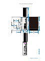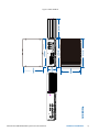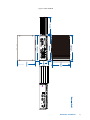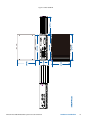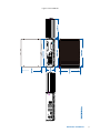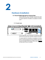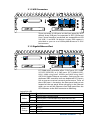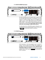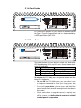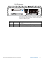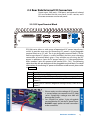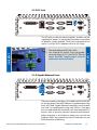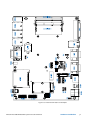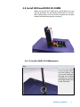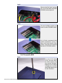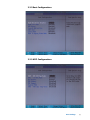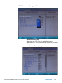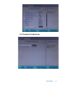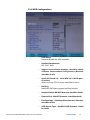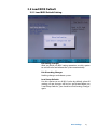
1
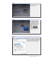
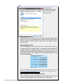
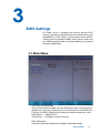
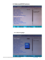
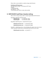
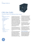
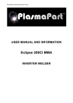
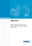
1.0.2 Edition 11/10/2012
All information is subject to change without notice.
Worldwide Technical Support and Product Information
www.vecow.com
Vecow Corporate Headquarters
7F No 105 Zhongcheng Rd Tucheng Dist New Taipei City 23674 Taiwan R.O.C.
Tel: 886 2 2268 5658
Fax: 886 2 2268 1658
For further support information, refer to the Technical Support and Professional Services
appendix. To comment on Vecow Co., Ltd. documentation, refer to the Vecow Co., Ltd.
web site at www.vecow.com.
© 2011–2012 Vecow Co., Ltd. All rights reserved.
Record of Revision
Version
V1.00
V1.01
V1.02
Date
Jun 12, 2012
Sep 05, 2012
Oct 11, 2012
Page
All
V, 7, 15, 68
22, 54, 55
Description
Remark
Preliminary Release
ECS-5600-8R Added, 4.7 deleted
RS-422 mode and SIO Configuration
Declaimer
This manual is intended to be used as a practical and informative guide
only and is subject to change without prior notice. It does not represent
commitment from Vecow Co., Ltd. Vecow shall not be liable for direct, indirect,
special, incidental, or consequential damages arising out of the use of the
product or documentation, nor for any infringements upon the rights of third
parties, which may result from such use.
Declaration of Conformity
FCCThis equipment has been tested and found to comply with the limits for a
Class A digital device, pursuant to part 15 of the FCC Rules. These limits are
designed to provide reasonable protection against harmful interference when
the equipment is operated in a commercial environment. This equipment
generates, uses, and can radiate radio frequency energy and, if not installed
and used in accordance with the instruction manual, may cause harmful
interference to radio communications. Operation of this equipment in a
residential area is likely to cause harmful interference in which case the user will
be required to correct the interference at his own expense.
CE
The product(s) described in this manual complies with all applicable European
Union (CE) directives if it has a CE marking. For computer systems to remain CE
compliant, only CE-compliant parts may be used. Maintaining CE compliance
also requires proper cable and cabling techniques.
Copyright and Trademarks
This document contains proprietary information protected by copyright.
All rights are reserved. No part of this document may be reproduced by any
mechanical, electronic, or other means in any form without prior written
permission of the manufacturer. Company/product names mentioned herein
are used for identification
©Vecow ECS-5600 Embedded System Series User Manual
iv
Packing List
Item
Description
Qty
1 ECS-5600 Series fanless controller
1
(According to the configuration you order, the ECS-5600 series may contain HDD
and DDR3 SO-DIMM. Please verify these items if necessary.)
2 Accessory box, which contains
• Vecow Drivers & Utilities DVD
1
• Wall-mounting bracket
2
• M4 screws for wall-mounting bracket
4
• Foot pad
4
• 4-pin pluggable terminal block
1
Order Information
Part Number
ECS-5600-3G
ECS-5600-5G
ECS-5600-5GD
ECS-5600-5GDE
ECS-5600-3V
ECS-5600-8R
ECS-5600-3R
ECS-5600-5R
Description
Extreme Fanless Embedded Controller with 3x GbE, 2x DDR3 SODIMM, 2x
eSATA, 4x COM, 2x MiniPCI-e, 2x HDD
Extreme Fanless Embedded Controller with 5x GbE, 2x DDR3 SODIMM, 2x
eSATA, 4x COM, 2x MiniPCI-e, 2x HDD
Extreme Fanless Embedded Controller with 5x GbE, 2x DDR3 SODIMM, 2x
eSATA, 4x COM, 2x MiniPCI-e, 2x HDD, Isolated DIO, AMT 7.0
Extreme Fanless Embedded Controller with 5x GbE, 2x DDR3 SODIMM, 2x
eSATA, 4x COM, 2x MiniPCI-e, 2x HDD, Isolated DIO, SUMIT (A, B), AMT 7.0
Fanless Embedded Controller with 4CH Video capture, 3x GbE, 2x DDR3
SODIMM, 2x eSATA, 4x COM, 2x MiniPCI-e, 2x HDD
Extreme Fanless Embedded Controller with 8x GbE, 2x DDR3 SODIMM, 2x
eSATA, 4x COM, 2x MiniPCI-e, 2x HDD, SUMIT (A, B), iAMT 7.0
Extreme Fanless Embedded Controller with 3x GbE, 2x DDR3 SODIMM, 2x
eSATA, 4x COM, 2x MiniPCI-e, 2x Removable HDD with Key Lock
Extreme Fanless Embedded Controller with 5x GbE, 2x DDR3 SODIMM, 2x
eSATA, 4x COM, 2x MiniPCI-e, 2x Removable HDD with Key Lock, AMT 7.0
Optional Accessories
Part Number
LSM-100-3
VSM-200-4
VSM-200-8
VMX-200-4
VMX-200-8
NVTE3G
DN WiFI
PWA-90W
Description
SUMIT, 3 Gigabit Ethernet Card
4-CH, D1, Real-time, SUMIT(PCIe), 120 fps, Video Capture Card, include cables
and SDK
8-CH, D1, Real-time, SUMIT(PCIe), 240 fps, Video Capture Card, include cables
and SDK
4-CH, D1, Real-time, Mini-PCI Express, 120 fps, Video Capture Card, include
cables and SDK
8-CH, D1, Real-time, Mini-PCI Express, 240 fps, Video Capture Card, include
cables and SDK
3G module, MiniPCI-e, W/HSPA+/UMTS 850/900/AWS/1900/2100 MHz, EGPRS
850/900/1800/1900 MHz
802.11n a/b/g WiFi, 2Tx/2R, Mini-PCIe
90W, 24V, 90VAC to 264VAC power adapter
v
Table of Contents
Declaimeriv
Declaration of Conformity
iv
Copyright and Trademarks
iv
FCCiv
CEiv
Packing List
Order Information
Optional Accessories
General Introduction
v
v
v
1
1.1 Overview
1.2 Product Specification
1
2
1.2.1 Specification of Vecow ECS-5600-3G
1.2.2 Specification of Vecow ECS-5600-5G
1.2.3 Specification of Vecow ECS-5600-5GD
1.2.4 Specification of Vecow ECS-5600-5GDE
1.2.5 Specification of Vecow ECS-5600-3V
1.2.6 Specification of Vecow ECS-5600-8R
1.2.7 Specification of Vecow ECS-5600-3R
1.2.8 Specification of Vecow ECS-5600-5R
2
3
4
5
6
7
8
9
1.3 Supported CPU List
1.4 Mechanical Dimension
10
11
Hardware Installation
18
2.1 Front Side External I/O Connectors
18
2.1.1 Audio Jacks
2.1.2 USB Connectors
2.1.3 Gigabit Ethernet Port
2.1.4 DVI-D/HDMI Connector
2.1.5 VGA Connector
2.1.6 CFast Socket
2.1.7 Power Button
2.1.8 LED Indicators
18
19
19
20
20
21
21
22
2.2 Rear Side External I/O Connectors
23
2.3 SUMIT A, B
2.4 Install HDD and DDR3 SO-DIMM
28
31
2.5 Wall-Mount EC-5500 series 2.6 Power Supply
36
38
2.7 Power Management & Function Settings
40
2.2.1 DC Input Terminal Block
2.2.2 DC Jack
2.2.3 Gigabit Ethernet Ports
2.2.4 COM Ports
2.2.5 Isolated DIO
2.2.6 eSATA Ports
23
24
24
25
26
27
2.4.1 To install a DDR3 SO-DIMM module
2.4.2 To install a HDD
2.4.2 To install a HDD
31
32
33
2.6.1 To connect DC power via the 4-pin pluggable terminal block
38
2.7.1 Power-On Modes Behavior
2.7.2 Using the power button on the front panel
2.7.3 Using remote on/off control on the rear panel
2.7.4 Using Wake-on-LAN function
40
42
42
43
vi
BIOS Settings
46
3.1 Main Menu
3.2 Advanced BIOS Features
46
47
3.2.1 Select Languages
3.2.2 Boot Configurations
3.2.3 ACPI Configurations
3.2.4 Processor Configurations
3.2.5 Peripheral Configurations
3.2.6 HDD Configurations
3.2.7 Memory Configurations
3.2.8 System Agent (SA) Configurations
3.2.9 South Bridge Configurations
3.2.10 Network Configurations
3.2.11 SMBIOS Event Log
3.2.12 AMT Configurations
3.2.13 ME Configurations
3.2.14 Thermal Configurations
3.2.15 Intel Fast Flash Standby
3.2.16 Intel Always On Connected
47
48
48
49
50
51
52
52
53
55
56
56
57
57
58
58
3.3 Super IO
59
3.4 Security
63
3.5 Load BIOS Default
64
Software Installation
65
3.3.1 SIO Configurations
3.3.2 Hardware Monitor
59
62
3.4.1 Set Supervisor Password
3.4.2 Clear Supervisor Password
63
63
3.5.1 Load BIOS Default Setting
64
4.1 Chipset Driver Installation
4.2 Graphic Driver Installation
4.3 Network Device Driver Installation
4.4 Audio Device Driver Installation
4.5 ME Driver Installation
4.6 Intel Rapid Software Installation
65
66
67
67
68
69
Appendix A : Isolating DIO Guide
70
Appendix B : GPIO & WDT Function
73
2
A. Build the base protocol for I C/SMBus access
B. Access DIO Controller using I2C/SMBus access function
C. Initialized the DIO controller
A.
B.
C.
D.
E.
71
71
72
Entry Super I/O configuration mode
Located on Logical Device 7
Access the Super I/O register
Start to Access the ECS-5600 GPIO port
WDT ON/OFF and Timer-Counter setting
73
73
73
73
74
G
1
General Introduction
1.1 Overview
ECS-5600 series, High Performance Fanless Embedded
Controller, which enables to integrated 2nd Gen Intel®
Core™ i7, i5, i3, and Celeron® Sandy Bridge mobile series
processors equips maximum 5 GbE LANs, DVI-D/HDMI and
VGA dual display, CFast, SUMIT™ A, B, and two 2.5” SATA
6Gp/s HDD/SSDs, and 2 eSATA ports, plus with superior
fanless thermal and housing structure enables systems
operating under -25ºC to +70ºC.
Designed for harsh operation environment, wide
vibration and shocks resistances, and high flexibility of
card expansion. In order to satisfy diverse requirements
of in-vehicle and industrial markets, ECS-5600 series are
constructed with wide DC input range from 6 to 36 voltages
to ensure system stability and safety.
Specifically designed for flexible data storage and security,
ECS-5600-3R/5R series equipped with 2 front-panel access
SATA III (6Gb/s) 2.5” removable HDD/SSD trays with key lock.
For industrial automation application, Vecow also provide
ECS-5600-5GD/5GDE series with Isolated DIO and SUMIT
A, B enable better power supply protection and various I/
O adoptions to select. Integrated all outstanding features,
the new ECS-5600 series are ideal solutions for various
applications, for example, in-vehicle surveillance, factory/
machine automation, medicine and healthcare, digital
signage and environment monitoring.
General Introduction
1
1.2 Product Specification
1.2.1 Specification of Vecow ECS-5600-3G
System
Processor
Chipset
BIOS
SIO
Memory
I/O Ports
Serial Port
USB Interface
LED
GPIO
Expansion
Mini PCIe
Graphics
Chipset
Display Memory
Interface
Storage
SATA
Storage Expansion
eSATA
Audio
Audio Codec
Audio Interface
Ethernet
LAN1
LAN2
LAN3
Power
Power Input
Power Input Voltage
Power Adapter
Other
Watchdog Timer
HW Monitor
Mechanical
Chasis Construction
Size (W x D x H)
Weight
Mounting
Environmental
Operating Temperature
Storage Temperature
Humidity
Vibration
Shock
EMC
2nd Generation Intel® Core™ i7/i5/i3 and Celeron™ Mobile, Sandy Bridge Processors
Intel® QM67
Phoenix UEFI BIOS
Nuvoton NCT6106D
DDR3 1333 / 1066MHz
Max. 16GB
2 204-pin SO-DIMM Sockets
3 COM RS-232, 1 COM RS-232/485/422
6 USB Ports, Compliant with USB 2.0
Power/Suspend, HDD, and WDT LEDs
8 DI, 8 DO
2 Mini PCIe, 1 SIM Socket on 1 Mini PCIe Interface
Intel® GMA HD 3000
Shared Memory, Up to 1.7GB
VGA + DVI-D / HDMI
Onboard VGA, Supports Max. Resolution 2048 x 1536 (@60Hz)
Onboard DVI-D, Supports Max. Resolution 1920 x 1200
2 SATA III (6Gbps) 2.5" HDD / SSD Drive Bays
CFast Slot, External Hot-Swap, Push In/Out Ejector
2 eSATA Ports
Realtek ALC892, 5.1 channel HD Audio
Line-in, Line-out, Mic-in, Front Audio Header
Intel® 82574L Gigabit LAN
Intel® 82574L Gigabit LAN
Intel® 82574L Gigabit LAN
DC Jack, 2-pin Terminal Block
DC-IN 6 ~ 36 V
AC to DC +24V / 3.75A. 90W Max. (Optional)
Reset: 1 to 255 sec./min. Per Step
Temperature/Voltages Auto Throttling Control When CPU Overheats
Aluminum Housing
260mm x 175mm x 78mm (10.2" x 6.9" x 3.1")
2.8 Kg (6 lb)
Wall-mount by Mounting Bracket
-25°C to 70°C (-4°F to 157°F)
-40°C to 85°C (-40°F to 185°F)
10% to 95% Humidity, Non-condensing
Operating, 5 Grms, 5-500 Hz, 3 Axes (w/ SSD, According to IEC60068-2-64)
Operating, 50 Grms, Half-sine 11 ms Duration (w/ SSD, According to IEC60068-2-27)
CE, FCC, RoHS, EN50155 & EN50121-3-2
©Vecow ECS-5600 Embedded System Series User Manual
General Introduction
2
1.2.2 Specification of Vecow ECS-5600-5G
System
Processor
Chipset
BIOS
SIO
Memory
I/O Ports
Serial Port
USB Interface
LED
GPIO
Expansion
Mini PCIe
Graphics
Chipset
Display Memory
Interface
Storage
SATA
Storage Expansion
eSATA
Audio
Audio Codec
Audio Interface
Ethernet
LAN1
LAN2
LAN3
LAN4
LAN5
Power
Power Input
Power Input Voltage
Power Adapter
Other
Watchdog Timer
HW Monitor
Mechanical
Chasis Construction
Size (W x D x H)
Weight
Mounting
Environmental
Operating Temperature
Storage Temperature
Humidity
Vibration
Shock
EMC
2nd Generation Intel® Core™ i7/i5/i3 and Celeron™ Mobile, Sandy Bridge Processors
Intel® QM67
Phoenix UEFI BIOS
Nuvoton NCT6106D
DDR3 1333 / 1066MHz
Max. 16GB
2 204-pin SO-DIMM Sockets
3 COM RS-232, 1 COM RS-232/485/422
6 USB Ports, Compliant with USB 2.0
Power/Suspend, HDD, and WDT LEDs
8 DI, 8 DO
2 Mini PCIe, 1 SIM Socket on 1 Mini PCIe Interface
Intel® GMA HD 3000
Shared Memory, Up to 1.7GB
VGA + DVI-D / HDMI
Onboard VGA, Supports Max. Resolution 2048 x 1536 (@60Hz)
Onboard DVI-D, Supports Max. Resolution 1920 x 1200
2 SATA III (6Gbps) 2.5" HDD / SSD Drive Bays
CFast Slot, External Hot-Swap, Push In/Out Ejector
2 eSATA Ports
Realtek ALC892, 5.1 channel HD Audio
Line-in, Line-out, Mic-in, Front Audio Header
Intel® 82574L Gigabit LAN
Intel® 82574L Gigabit LAN
Intel® 82574L Gigabit LAN
Intel® 82574L Gigabit LAN
Intel® 82579LM Gigabit LAN
DC Jack, 2-pin Terminal Block
DC-IN 6 ~ 36 V
AC to DC +24V / 3.75A. 90W Max. (Optional)
Reset: 1 to 255 sec./min. Per Step
Temperature/Voltages Auto Throttling Control When CPU Overheats
Aluminum Housing
260mm x 175mm x 78mm (10.2" x 6.9" x 3.1")
2.8 Kg (6 lb)
Wall-mount by Mounting Bracket
-25°C to 70°C (-4°F to 157°F)
-40°C to 85°C (-40°F to 185°F)
10% to 95% Humidity, Non-condensing
Operating, 5 Grms, 5-500 Hz, 3 Axes (w/ SSD, According to IEC60068-2-64)
Operating, 50 Grms, Half-sine 11 ms Duration (w/ SSD, According to IEC60068-2-27)
CE, FCC, RoHS, EN50155 & EN50121-3-2
General Introduction
3
1.2.3 Specification of Vecow ECS-5600-5GD
System
Processor
Chipset
BIOS
SIO
Memory
I/O Ports
Serial Port
USB Interface
Isolated DIO
LED
GPIO
Expansion
Mini PCIe
Graphics
Chipset
Display Memory
Interface
Storage
SATA
Storage Expansion
eSATA
Audio
Audio Codec
Audio Interface
Ethernet
LAN1
LAN2
LAN3
LAN4
LAN5
Power
Power Input
Power Input Voltage
Power Adapter
Other
Watchdog Timer
HW Monitor
Mechanical
Chasis Construction
Size (W x D x H)
Weight
Mounting
Environmental
Operating Temperature
Storage Temperature
Humidity
Vibration
Shock
EMC
2nd Generation Intel® Core™ i7/i5/i3 and Celeron™ Mobile, Sandy Bridge Processors
Intel® QM67
Phoenix UEFI BIOS
Nuvoton NCT6106D
DDR3 1333 / 1066MHz
Max. 16GB
2 204-pin SO-DIMM Sockets
3 COM RS-232, 1 COM RS-232/485/422
6 USB Ports, Compliant with USB 2.0
8 DI, 8 DO
Power/Suspend, HDD, and WDT LEDs
8 DI, 8 DO
2 Mini PCIe, 1 SIM Socket on 1 Mini PCIe Interface
Intel® GMA HD 3000
Shared Memory, Up to 1.7GB
VGA + DVI-D / HDMI
Onboard VGA, Supports Max. Resolution 2048 x 1536 (@60Hz)
Onboard DVI-D, Supports Max. Resolution 1920 x 1200
2 SATA III (6Gbps) 2.5" HDD / SSD Drive Bays
CFast Slot, External Hot-Swap, Push In/Out Ejector
2 eSATA Ports
Realtek ALC892, 5.1 channel HD Audio
Line-in, Line-out, Mic-in, Front Audio Header
Intel® 82574L Gigabit LAN
Intel® 82574L Gigabit LAN
Intel® 82574L Gigabit LAN
Intel® 82574L Gigabit LAN
Intel® 82579LM Gigabit LAN
DC Jack, 2-pin Terminal Block
DC-IN 6 ~ 36 V
AC to DC +24V / 3.75A. 90W Max. (Optional)
Reset: 1 to 255 sec./min. Per Step
Temperature/Voltages Auto Throttling Control When CPU Overheats
Aluminum Housing
260mm x 175mm x 78mm (10.2" x 6.9" x 3.1")
2.8 Kg (6 lb)
Wall-mount by Mounting Bracket
-25°C to 70°C (-4°F to 157°F)
-40°C to 85°C (-40°F to 185°F)
10% to 95% Humidity, Non-condensing
Operating, 5 Grms, 5-500 Hz, 3 Axes (w/ SSD, According to IEC60068-2-64)
Operating, 50 Grms, Half-sine 11 ms Duration (w/ SSD, According to IEC60068-2-27)
CE, FCC, RoHS, EN50155 & EN50121-3-2
©Vecow ECS-5600 Embedded System Series User Manual
General Introduction
4
1.2.4 Specification of Vecow ECS-5600-5GDE
System
Processor
Chipset
BIOS
SIO
Memory
I/O Ports
Serial Port
USB Interface
Isolated DIO
LED
GPIO
Expansion
Mini PCIe
SUMIT A, B
Graphics
Chipset
Display Memory
Interface
Storage
SATA
Storage Expansion
eSATA
Audio
Audio Codec
Audio Interface
Ethernet
LAN1
LAN2
LAN3
LAN4
LAN5
Power
Power Input
Power Input Voltage
Power Adapter
Other
Watchdog Timer
HW Monitor
Mechanical
Chasis Construction
Size (W x D x H)
Weight
Mounting
Environmental
Operating Temperature
Storage Temperature
Humidity
Vibration
Shock
EMC
2nd Generation Intel® Core™ i7/i5/i3 and Celeron™ Mobile, Sandy Bridge Processors
Intel® QM67
Phoenix UEFI BIOS
Nuvoton NCT6106D
DDR3 1333 / 1066MHz
Max. 16GB
2 204-pin SO-DIMM Sockets
3 COM RS-232, 1 COM RS-232/485/422
6 USB Ports, Compliant with USB 2.0
8 DI, 8 DO
Power/Suspend, HDD, and WDT LEDs
8 DI, 8 DO
2 Mini PCIe, 1 SIM Socket on 1 Mini PCIe Interface
2 SUMIT Slots
Intel® GMA HD 3000
Shared Memory, Up to 1.7GB
VGA + DVI-D / HDMI
Onboard VGA, Supports Max. Resolution 2048 x 1536 (@60Hz)
Onboard DVI-D, Supports Max. Resolution 1920 x 1200
2 SATA III (6Gbps) 2.5" HDD / SSD Drive Bays
CFast Slot, External Hot-Swap, Push In/Out Ejector
2 eSATA Ports
Realtek ALC892, 5.1 channel HD Audio
Line-in, Line-out, Mic-in, Front Audio Header
Intel® 82574L Gigabit LAN
Intel® 82574L Gigabit LAN
Intel® 82574L Gigabit LAN
Intel® 82574L Gigabit LAN
Intel® 82579LM Gigabit LAN
DC Jack, 2-pin Terminal Block
DC-IN 6 ~ 36 V
AC to DC +24V / 3.75A. 90W Max. (Optional)
Reset: 1 to 255 sec./min. Per Step
Temperature/Voltages Auto Throttling Control When CPU Overheats
Aluminum Housing
260mm x 175mm x 78mm (10.2" x 6.9" x 3.1")
2.8 Kg (6 lb)
Wall-mount by Mounting Bracket
-25°C to 70°C (-4°F to 157°F)
-40°C to 85°C (-40°F to 185°F)
10% to 95% Humidity, Non-condensing
Operating, 5 Grms, 5-500 Hz, 3 Axes (w/ SSD, According to IEC60068-2-64)
Operating, 50 Grms, Half-sine 11 ms Duration (w/ SSD, According to IEC60068-2-27)
CE, FCC, RoHS, EN50155 & EN50121-3-2
General Introduction
5
1.2.5 Specification of Vecow ECS-5600-3V
System
Processor
Chipset
BIOS
SIO
Memory
I/O Ports
Serial Port
USB Interface
LED
GPIO
Expansion
Mini PCIe
Graphics
Chipset
Display Memory
Interface
Storage
SATA
Storage Expansion
eSATA
Audio
Audio Codec
Audio Interface
Maximum Channel No.
Input Connector
Video
Maximum Channel No.
Input Connector
Resolution
Recording Rate
Ethernet
LAN1
LAN2
LAN3
Power
Power Input
Power Input Voltage
Power Adapter
Other
Watchdog Timer
HW Monitor
Mechanical
Chasis Construction
Size (W x D x H)
Weight
Mounting
Environmental
Operating Temperature
Storage Temperature
Humidity
Vibration
Shock
EMC
2nd Generation Intel® Core™ i7/i5/i3 and Celeron™ Mobile, Sandy Bridge Processors
Intel® QM67
Phoenix UEFI BIOS
Nuvoton NCT6106D
DDR3 1333 / 1066MHz
Max. 16GB
2 204-pin SO-DIMM Sockets
3 COM RS-232, 1 COM RS-232/485/422
6 USB Ports, Compliant with USB 2.0
Power/Suspend, HDD, and WDT LEDs
8 DI, 8 DO
2 Mini PCIe, 1 SIM Socket on 1 Mini PCIe Interface
Intel® GMA HD 3000
Shared Memory, Up to 1.7GB
VGA + DVI-D / HDMI
Onboard VGA, Supports Max. Resolution 2048 x 1536 (@60Hz)
Onboard DVI-D, Supports Max. Resolution 1920 x 1200
2 SATA III (6Gbps) 2.5" HDD / SSD Drive Bays with Key Lock
CFast Slot, External Hot-Swap, Push In/Out Ejector
2 eSATA Ports
Realtek ALC892, 5.1 channel HD Audio
Line-in, Line-out, Mic-in, Front Audio Header
4 Mono or 2 Stereo
4 Input RCA on Board
4
4 Input BNC on Board
D1 (NTSC: 720x480/PAL:720x576), CIF (NTSC:360x240/PAL:360x288)
4CIF (NTSC:704x480/PAL:704x576), DCIF (NTSC:528x320/PAL:528x384)
QCIF (NTSC:180x120/PAL:180x144),
4CH with full D1 resolution
120 fps on NTSC system, 100 fps on PAL system
Intel® 82574L Gigabit LAN
Intel® 82574L Gigabit LAN
Intel® 82574L Gigabit LAN
DC Jack, 2-pin Terminal Block
DC-IN 6 ~ 36 V
AC to DC +24V / 3.75A. 90W Max. (Optional)
Reset: 1 to 255 sec./min. Per Step
Temperature/Voltages Auto Throttling Control When CPU Overheats
Aluminum Housing
260mm x 175mm x 78mm (10.2" x 6.9" x 3.1")
2.8 Kg (6 lb)
Wall-mount by Mounting Bracket
-25°C to 70°C (-4°F to 157°F)
-40°C to 85°C (-40°F to 185°F)
10% to 95% Humidity, Non-condensing
Operating, 5 Grms, 5-500 Hz, 3 Axes (w/ SSD, According to IEC60068-2-64)
Operating, 50 Grms, Half-sine 11 ms Duration (w/ SSD, According to IEC60068-2-27)
CE, FCC, RoHS, EN50155 & EN50121-3-2
©Vecow ECS-5600 Embedded System Series User Manual
General Introduction
6
1.2.6 Specification of Vecow ECS-5600-8R
System
Processor
Chipset
BIOS
SIO
Memory
I/O Ports
Serial Port
USB Interface
LED
GPIO
Expansion
Mini PCIe
SUMIT A, B
Graphics
Chipset
Display Memory
Interface
Storage
SATA
Storage Expansion
eSATA
Audio
Audio Codec
Audio Interface
Ethernet
LAN1~4
LAN5
LAN6~8
Power
Power Input
Power Input Voltage
Power Adapter
Other
Watchdog Timer
HW Monitor
Mechanical
Chasis Construction
Size (W x D x H)
Weight
Mounting
Environmental
Operating Temperature
Storage Temperature
Humidity
Vibration
Shock
EMC
2nd Generation Intel® Core™ i7/i5/i3 and Celeron™ Mobile, Sandy Bridge Processors
Intel® QM67
Phoenix UEFI BIOS
Nuvoton NCT6106D
DDR3 1333 / 1066MHz
Max. 16GB
2 204-pin SO-DIMM Sockets
3 COM RS-232, 1 COM RS-232/485/422
6 USB Ports, Compliant with USB 2.0
Power/Suspend, HDD, and WDT LEDs
8 DI, 8 DO
2 Mini PCIe, 1 SIM Socket on 1 Mini PCIe Interface
2 SUMIT Slots
Intel® GMA HD 3000
Shared Memory, Up to 1.7GB
VGA + DVI-D / HDMI
Onboard VGA, Supports Max. Resolution 2048 x 1536 (@60Hz)
Onboard DVI-D, Supports Max. Resolution 1920 x 1200
2 SATA III (6Gbps) 2.5" HDD / SSD Drive Bays with Key Lock
CFast Slot, External Hot-Swap, Push In/Out Ejector
2 eSATA Ports
Realtek ALC892, 5.1 channel HD Audio
Line-in, Line-out, Mic-in, Front Audio Header
Intel® 82574L Gigabit LAN
Intel® 82579LM Gigabit LAN
Intel® 82574L Gigabit LAN
DC Jack, 2-pin Terminal Block
DC-IN 6 ~ 36 V
AC to DC +24V / 3.75A. 90W Max. (Optional)
Reset: 1 to 255 sec./min. Per Step
Temperature/Voltages Auto Throttling Control When CPU Overheats
Aluminum Housing
260mm x 175mm x 78mm (10.2" x 6.9" x 3.1")
2.8 Kg (6 lb)
Wall-mount by Mounting Bracket
-25°C to 70°C (-4°F to 157°F)
-40°C to 85°C (-40°F to 185°F)
10% to 95% Humidity, Non-condensing
Operating, 5 Grms, 5-500 Hz, 3 Axes (w/ SSD, According to IEC60068-2-64)
Operating, 50 Grms, Half-sine 11 ms Duration (w/ SSD, According to IEC60068-2-27)
CE, FCC, RoHS, EN50155 & EN50121-3-2
General Introduction
7
1.2.7 Specification of Vecow ECS-5600-3R
System
Processor
Chipset
BIOS
SIO
Memory
I/O Ports
Serial Port
USB Interface
LED
GPIO
Expansion
Mini PCIe
Graphics
Chipset
Display Memory
Interface
Storage
SATA
Storage Expansion
eSATA
Audio
Audio Codec
Audio Interface
Ethernet
LAN1
LAN2
LAN3
Power
Power Input
Power Input Voltage
Power Adapter
Other
Watchdog Timer
HW Monitor
Mechanical
Chasis Construction
Size (W x D x H)
Weight
Mounting
Environmental
Operating Temperature
Storage Temperature
Humidity
Vibration
Shock
EMC
2nd Generation Intel® Core™ i7/i5/i3 and Celeron™ Mobile, Sandy Bridge Processors
Intel® QM67
Phoenix UEFI BIOS
Nuvoton NCT6106D
DDR3 1333 / 1066MHz
Max. 16GB
2 204-pin SO-DIMM Sockets
3 COM RS-232, 1 COM RS-232/485/422
6 USB Ports, Compliant with USB 2.0
Power/Suspend, HDD, and WDT LEDs
8 DI, 8 DO
2 Mini PCIe, 1 SIM Socket on 1 Mini PCIe Interface
Intel® GMA HD 3000
Shared Memory, Up to 1.7GB
VGA + DVI-D / HDMI
Onboard VGA, Supports Max. Resolution 2048 x 1536 (@60Hz)
Onboard DVI-D, Supports Max. Resolution 1920 x 1200
2 SATA III (6Gbps) 2.5" HDD / SSD Drive Bays with Key Lock
CFast Slot, External Hot-Swap, Push In/Out Ejector
2 eSATA Ports
Realtek ALC892, 5.1 channel HD Audio
Line-in, Line-out, Mic-in, Front Audio Header
Intel® 82574L Gigabit LAN
Intel® 82574L Gigabit LAN
Intel® 82574L Gigabit LAN
DC Jack, 2-pin Terminal Block
DC-IN 6 ~ 36 V
AC to DC +24V / 3.75A. 90W Max. (Optional)
Reset: 1 to 255 sec./min. Per Step
Temperature/Voltages Auto Throttling Control When CPU Overheats
Aluminum Housing
260mm x 175mm x 78mm (10.2" x 6.9" x 3.1")
2.8 Kg (6 lb)
Wall-mount by Mounting Bracket
-25°C to 70°C (-4°F to 157°F)
-40°C to 85°C (-40°F to 185°F)
10% to 95% Humidity, Non-condensing
Operating, 5 Grms, 5-500 Hz, 3 Axes (w/ SSD, According to IEC60068-2-64)
Operating, 50 Grms, Half-sine 11 ms Duration (w/ SSD, According to IEC60068-2-27)
CE, FCC, RoHS, EN50155 & EN50121-3-2
©Vecow ECS-5600 Embedded System Series User Manual
General Introduction
8
1.2.8 Specification of Vecow ECS-5600-5R
System
Processor
Chipset
BIOS
SIO
Memory
I/O Ports
Serial Port
USB Interface
LED
GPIO
Expansion
Mini PCIe
Graphics
Chipset
Display Memory
Interface
Storage
SATA
Storage Expansion
eSATA
Audio
Audio Codec
Audio Interface
Ethernet
LAN1
LAN2
LAN3
LAN4
LAN5
Power
Power Input
Power Input Voltage
Power Adapter
Other
Watchdog Timer
HW Monitor
Mechanical
Chasis Construction
Size (W x D x H)
Weight
Mounting
Environmental
Operating Temperature
Storage Temperature
Humidity
Vibration
Shock
EMC
2nd Generation Intel® Core™ i7/i5/i3 and Celeron™ Mobile, Sandy Bridge Processors
Intel® QM67
Phoenix UEFI BIOS
Nuvoton NCT6106D
DDR3 1333 / 1066MHz
Max. 16GB
2 204-pin SO-DIMM Sockets
3 COM RS-232, 1 COM RS-232/485/422
6 USB Ports, Compliant with USB 2.0
Power/Suspend, HDD, and WDT LEDs
8 DI, 8 DO
2 Mini PCIe, 1 SIM Socket on 1 Mini PCIe Interface
Intel® GMA HD 3000
Shared Memory, Up to 1.7GB
VGA + DVI-D / HDMI
Onboard VGA, Supports Max. Resolution 2048 x 1536 (@60Hz)
Onboard DVI-D, Supports Max. Resolution 1920 x 1200
2 SATA III (6Gbps) 2.5" HDD / SSD Drive Bays with Key Lock
CFast Slot, External Hot-Swap, Push In/Out Ejector
2 eSATA Ports
Realtek ALC892, 5.1 channel HD Audio
Line-in, Line-out, Mic-in, Front Audio Header
Intel® 82574L Gigabit LAN
Intel® 82574L Gigabit LAN
Intel® 82574L Gigabit LAN
Intel® 82574L Gigabit LAN
Intel® 82579LM Gigabit LAN
DC Jack, 2-pin Terminal Block
DC-IN 6 ~ 36 V
AC to DC +24V / 3.75A. 90W Max. (Optional)
Reset: 1 to 255 sec./min. Per Step
Temperature/Voltages Auto Throttling Control When CPU Overheats
Aluminum Housing
260mm x 175mm x 78mm (10.2" x 6.9" x 3.1")
2.8 Kg (6 lb)
Wall-mount by Mounting Bracket
-25°C to 70°C (-4°F to 157°F)
-40°C to 85°C (-40°F to 185°F)
10% to 95% Humidity, Non-condensing
Operating, 5 Grms, 5-500 Hz, 3 Axes (w/ SSD, According to IEC60068-2-64)
Operating, 50 Grms, Half-sine 11 ms Duration (w/ SSD, According to IEC60068-2-27)
CE, FCC, RoHS, EN50155 & EN50121-3-2
General Introduction
9
1.3 Supported CPU List
Vecow ECS-5600 accepts 2nd generation Intel® i7/i5/i3
processors via a rPGA988B CPU socket. The following
processors have been tested by Vecow Co., Ltd. for
the compatibility with Vecow ECS-5600. Instead of i72710QE, i5-2510E and i3-2330E, You may also select
other processor according to your consideration of cost
and performance.
Series
i7
2620M
2630QM
2640M
2670QM
2710QE
2720QM
i5
2410M
2430M
2520M
2510E
2540M
i3
2310M*
2312M*
2330E
2330M*
2350M*
Celeron B710
B800
B810
B840
Socket
rPGA988B
rPGA988B
rPGA988B
rPGA988B
Max. TDP Embedded
35W
45W
35W
45W
45W
√
45W
35W
35W
35W
35W
√
35W
35W
35W
35W
√
35W
35W
35W
35W
35W
√
35W
The processors with "√" are listed in Intel® Embedded Roadmap
and with a 7-year life cycle support (from 2011 to 2017). The
processors with "* " the maximum operation temperature is
55OC.
©Vecow ECS-5600 Embedded System Series User Manual
General Introduction
10
1.4 Mechanical Dimension
Figure 1.1 ECS-5600-3G
General Introduction
11
Figure 1.2 ECS-5600-5G
©Vecow ECS-5600 Embedded System Series User Manual
General Introduction
12
Figure 1.3 ECS-5600-5GD / ECS-5600-5GDE
Hardware Installation
13
Figure 1.4 ECS-5600-3V
©Vecow ECS-5600 Embedded System Series User Manual
Hardware Installation
14
Figure 1.5 ECS-5600-8R
Hardware Installation
15
Figure 1.6 ECS-5600-3R
©Vecow ECS-5600 Embedded System Series User Manual
Hardware Installation
16
Figure 1.7 ECS-5600-5R
Hardware Installation
17
2
Hardware Installation
2.1 Front Side External I/O Connectors
On ECS-5600 series, all I/O connectors are located on front
panel and rear panel. Most general computer connectors
(i.e. audio, USB, DVI-D, VGA and etc.) are placed on the front
panel.
2.1.1 Audio Jacks
On ECS-5600 series, all I/O connectors are located on front
panel and rear panel. Most general computer connectors
(i.e. audio, USB, DVI-D, VGA and etc.) are placed on the front
panel. To utilize the audio function in Windows, you need
to install corresponding drivers for both Intel® QM67 PCH
chipset and Realtek ALC892 codec. Please refer to section 4
for information of driver installation.
©Vecow ECS-5600 Embedded System Series User Manual
Hardware Installation
18
2.1.2 USB Connectors
5/6
3
3/4
2
1/2
1
There are totally 6 USB ports on the front panel. By BIOS
default, these USB ports are operated in EHCI (Enhanced
Host Control Interface) mode and are compatible to USB
2.0, USB 1.1 and USB 1.0 devices. Legacy USB support is
provided so you can use USB keyboard/mouse in DOS
environment.
2.1.3 Gigabit Ethernet Port
5/6
3
3/4
2
1/2
1
ECS-5600 series controller offers 5 GbE ports (ECS-56005G/5GD/5GDE/5R) or 3 GbE ports (ECS-5600-3G/3R),
LAN1~LAN4 using Intel® 82583v and LAN5 using Intel®
82579LM Gigabit Ethernet controllers. Each port has one
dedicated GbE controller and one dedicated PCI Express
link to present maximal network performance. Three of
these GbE ports is located on the front panel and two are
located on the rear panel. When plugging in the Ethernet
cable, you can tell the Ethernet status and speed from the
LED indicators on the RJ45 connector as following:
Active/Link LED
LED Color Status
Off
Yellow On
Flashing
Speed LED
LED Color Status
Off
Green /
Green
Orange
Orange
Description
Ethernet port is disconnected
Ethernet port is connected and no data transmission
Ethernet port is connected and data is transmitting/receiving
Description
10 Mbps
100 Mbps
1000 Mbps
Hardware Installation
19
2.1.4 DVI-D/HDMI Connector
DVI-D
The DVI-D connector on the front panel supports both
DVI and HDMI operation mode. This connector can either
output DVI signals or HDMI signal. The DVI output mode
supports up to 1920x1200 resolution and HDMI output
mode supports up to 1920x1200 resolution. The DVI or
HDMI mode is automatically selected according to the
display device connected. You shall need a DVI-D to HDMI
cable when connecting to a HDMI display device.
To utilize the VGA or DVI/HDMI output in Windows, you
need to install corresponding graphics driver. Please refer
to section 4 for information of driver installation.
2.1.5 VGA Connector
VGA
VGA connector is the most popular way to connect a
display. The VGA output of ECS-5600 series supports up
to 2048 x 1536 resolution. By BIOS default, both VGA and
DVI/HDMI output are enabled. To utilize the VGA or DVI/
HDMI output in Windows, you need to install corresponding
graphics driver. Please refer to section 4 for information of
driver installation.
©Vecow ECS-5600 Embedded System Series User Manual
Hardware Installation
20
2.1.6 CFast Socket
VGA
ECS-5600 series provides a CFast socket on the front panel
for Type-I / Type-II CompactFlash card. It is implemented by
a SATA II port from QM67 PCH.
2.1.7 Power Button
The power button is a non-latched switch with dual color
LED for indicating S0, S3 and S5 status. Power button dualcolor LED indicator:
Status LED Display
System Situation
S0
Blue
System working
S3
Blinking Orange
Suspend to RAM
S5
Orange
System off with standby power
To turn on the ECS-5600, press the power button and the
blue LED is lighted up.
• To turn off the ECS-5600 series, you can either issue
a shutdown command in OS, or just simply press the
power button.
• In case of system halts, you can press and hold the
power button for 4 seconds to compulsorily shut down
the system.
• Please note that a 4 seconds interval is kept by the
system between two on/off operations (i.e. once turning
off the system, you shall wait for 4 seconds to initiate
another power-on operation).
Hardware Installation
21
2.1.8 LED Indicators
CFast
There are three LED indicators on the front panel: WDT,
CFast and HDD. The descriptions of these three LED are
listed in the following table.
Indicator Color
WDT
BlinkingYellow
CFast
HDD
Red
Green
Description
Watchdog timer indicator, flashing when watchdog timer
is started.
CF indictor, flashing when CFast device is active.
Hard drive indicator, flashing when SATA port is active.
©Vecow ECS-5600 Embedded System Series User Manual
Hardware Installation
22
2.2 Rear Side External I/O Connectors
Power input, GbE ports, COM ports and optional isolated
DIO are located on the rear panel. In this section, we’ll
illustrate connectors on the rear panel.
2.2.1 DC Input Terminal Block
ECS-500 series allows a wide range of operational DC power input from 6
to 36V. It provides two ways for connecting DC power: a 4-pin pluggable
terminal block or a DC jack. The 4-pin pluggable terminal block is fit for
field usage where DC power is usually provided. And the screw clamping
connection of terminal block gives a very reliable way of wiring the DC
power. In addition to 2 pins for DC power input (V+, V-), the terminal block
offers another 2 pins for remote on/off control (Ctrl+, Ctrl-). The following
table describes the pin definition of the pluggable terminal block. For detail
information of connecting DC power and remote on/off control, please refer
to section 2.6.
Pin
V+
VCtrl+
Ctrl-
Description
Positive polarity of DC power input.
Negative polarity of DC power input (usually power ground).
Control pin to connect Positive Voltage Level(+)/ACC or Push
Button(+).
Control pin to connect Negative Voltage Level(-)/GND or Push
Button(-).
Hardware Installation
CAUTION!
CAUTION!
1. Please make sure the voltage of DC power
is correct before you connect it to ECS-5600
series. Supplying a voltage over 60V will
damage the system.
2. You should use either 2-pin pluggable
terminal block or DC jack for DC power input.
DO NOT supply power to both connectors
at the same time.
23
2.2.2 DC Jack
The DC jack on the rear panel provides another way for
supplying DC power. It’s convenient for indoor usage where
AC power is usually available. The DC jack is designed to use
with a 12/19/24V AC/DC adapter with a ø2.5/5.5 plug.
CAUTION!
CAUTION!
1. The rated voltage of DC jack is 36V.
2. You should use either 2-pin pluggable
terminal block or DC jack for DC power
input. DO NOT supply power to both
connectors at the same time.
2.2.3 Gigabit Ethernet Ports
There are another 2 GbE ports (ECS-5600-5G/5GD/5GDE/5R)
on the rear panel. The LAN5 GbE port is implemented using
Intel® 82579LM Gigabit Ethernet controller, and the other
one LAN 4 is implemented using Intel 82583v . Each port
has one dedicated GbE controller and one dedicated PCI
Express link to present maximal network performance.
When plugging in the Ethernet cable, you can tell the
Ethernet status and speed from the LED indicators on the
RJ45 connector as following:
©Vecow ECS-5600 Embedded System Series User Manual
Hardware Installation
24
Active/Link LED
LED Color Status
Off
Yellow On
Flashing
Description
Ethernet port is disconnected
Ethernet port is connected and no data transmission
Ethernet port is connected and data is transmitting/receiving
Speed LED
LED Color Status
Off
Green /
Green
Orange
Orange
Description
10 Mbps
100 Mbps
1000 Mbps
To utilize the GbE port in Windows, you need to install corresponding driver for
Intel® 82583v GbE controller. Please refer to section 5 for information of driver
installation.
2.2.4 COM Ports
COM2
COM4
COM1
COM3
ECS-5600 series provides 4 COM ports via 9-pin D-Sub
male connectors for communicating with external devices.
These COM ports are implemented using industrial-grade
NCT6106D Super IO chip (-40 to 85°C) and provide up to
115200 bps baud rate. COM2 is a software-selectable RS232/422/485 port and COM1/COM3/COM4 is RS-232 only.
The operation mode of COM2 can be set in BIOS setup
utility (refer to section 3 for detail).
Pin#
1
2
3
4
5
6
7
8
9
COM2
RS-232 Mode RS-422 Mode
DCD
RX
TX
DTR
GND
DSR
RTS
CTS
N/C
422 TxD422 TxD+
422 RxD+
422 RxDGND
N/C
N/C
N/C
N/C
RS-485 Mode
(Two-wire 485)
485 TXD+ / RXD +
485 TXD- / RXD N/C
N/C
GND
N/C
N/C
N/C
N/C
COM1/COM3/COM4
RS-232 Mode
DCD
RX
TX
DTR
GND
DSR
RTS
CTS
RI
Hardware Installation
25
2.2.5 Isolated DIO
Specification
• SMBUS GPIO Controller PCA9555
• Insulation Rating (kVrms): 2.5kV rms
©Vecow ECS-5600 Embedded System Series User Manual
Hardware Installation
26
Connector Pin-Definition
Pin # Pin Name
1
+5V_ISO
2
DO-0
3
DO-3
4
GND-ISO
5
DO-5
6
DO-7
7
GND-ISO
8
DI-6
9
DI-1
10
GND-ISO
11
DI-0
12
DI-2
13
DI-4
14
+5V_ISO
15
GND-ISO
16
DO-1
17
DO-2
18
DO-4
19
DO-6
20
GND-ISO
21
GND-ISO
22
DI-5
23
DI-3
24
DI-7
25
GND-ISO
Description
Isolated +5V
Digital Output bit-0
Digital Output bit-3
Isolated GND
Digital Output bit-5
Digital Output bit-7
Isolated GND
Digital Input bit-6
Digital Input bit-1
Isolated GND
Digital Input bit-0
Digital Input bit-2
Digital Input bit-4
Isolated +5V
Isolated GND
Digital Output bit-1
Digital Output bit-2
Digital Output bit-4
Digital Output bit-6
Isolated GND
Isolated GND
Digital Input bit-5
Digital Input bit-3
Digital Input bit-7
Isolated GND
2.2.6 eSATA Ports
eSATA1
eSATA2
eSATA is a convenient way to extend storage devices.
Devices with SATA interface, such as hard drive and CD/DVD
drive, can be attached to the ECS-5600 series controller via
eSATA ports. In addition, eSATA interface supports hot-plug
if SATA controller is configured as AHCI (Advanced Host
Controller Interface) mode. Please refer to section 3.2.6 for
setting SATA controller mode in BIOS.
Hardware Installation
27
2.3 SUMIT A, B
SUMIT-A CN 18
Pin#
1
3
5
7
9
11
13
15
17
19
21
23
25
27
29
31
33
35
37
39
41
43
45
47
49
51
G1
Pin Name
Description
+5VSB
+3.3V
+3.3V
PCIE-CLKREQ0#
NC
USB_OC#67
NC
+5V
USB9_DATA+
USB9_DATA+5V
USB8_DATA+
USB8_DATA+5V
USB7_DATA+
USB7_DATA+5V
USB6_DATA+
USB6_DATAGND
PCIe1_TX+
PCIe1_TXGND
PCIe_RESET#
PCIe_WAKE#
+5V
GND
Central GND Plate
©Vecow ECS-5600 Embedded System Series User Manual
Pin#
2
4
6
8
10
12
14
16
18
20
22
24
26
28
30
32
34
36
38
40
42
44
46
48
50
52
G1
Pin Name
Description
+12V
SIO_SMB1_DAT
SIO_SMB1_CLK
NC
SPI_MISO
SPI_MOSI
SPI_CLK
SPI_CS0#
SPI_CS1#
NC
LPC_DRQ#
LPC_AD0
LPC_AD1
LPC_AD2
LPC_AD3
LPC_FRAME#
SERIRQ#
SIO_PRST#
CLK33M
GND
PCIe1_RX+
PCIe1_RXGND
PCIe1_CLK0+
PCIe1_CLK0GND
GND
Central GND Plate
Hardware Installation
28
SUMIT-B CN 17
Pin#
1
3
5
7
9
11
13
15
17
19
21
23
25
27
29
31
33
35
37
39
41
43
45
47
49
51
G1
Pin Name
GND
x1PCIe_TX+
x1PCIe_TXGND
x4PCIe-CLK_C0+
X4PCIe-CLK_C0GND
x4PCIe_TX0+
x4PCIe_TX0GND
x4PCIe_TX1+
x4PCIe_TX1GND
x4PCIe_TX2+
x4PCIe_TX2GND
x4PCIe_TX3+
x4PCIe_TX3GND
PCIe_RESET#
NC
+5V
+5V
+5V
+5V
+5V
GND
Description
PCIe x4 CLK+
PCIe x4 CLKPCIe x4 TX0+
PCIe x4 TX0PCIe x4 TX1+
PCIe x4 TX1PCIe x4 TX2+
PCIe x4 TX2PCIe x4 TX3+
PCIe x4 TX3-
Central GND Plate
Pin#
2
4
6
8
10
12
14
16
18
20
22
24
26
28
30
32
34
36
38
40
42
44
46
48
50
52
G1
Pin Name
GND
x1PCIe_TX+
x1PCIe_TXGND
X1PCIe-CLK_B0+
X1PCIe-CLK_B0GND
x4PCIe_RX0+
x4PCIe_RX0GND
x4PCIe_RX1+
x4PCIe_RX1GND
x4PCIe_RX2+
x4PCIe_RX2GND
x4PCIe_RX3+
x4PCIe_RX3GND
PCIE_WAKE#
NC
NC
+3.3V
+3.3V
+3.3V
+5VSB
GND
Description
PCIe x1 CLK+
PCIe x1 CLKPCIe x4 RX0+
PCIe x4 RX0PCIe x4 RX1+
PCIe x4 RX1PCIe x4 RX2+
PCIe x4 RX2PCIe x4 RX3+
PCIe x4 RX3-
Central GND Plate
Hardware Installation
29
Figure 2.3.1 Internal Connectors and Jumpers
©Vecow ECS-5600 Embedded System Series User Manual
Hardware Installation
30
2.4 Install HDD and DDR3 SO-DIMM
When you put the ECS-5600 series upside down, you can
see the “pet-door” on the bottom of the chassis. The “petdoor” design allows users to install or replace the memory
module and hard drive quickly and easily.
2.4.1 To install a DDR3 SO-DIMM module
Step1.
Put the ECS-5600
series upside down
on a flat surface. You
can see the “Pet-Door”
exposed. Use a Philips
screwdriver to loose
the M3 flat-head screw
on the “Pet-Door”.
Hardware Installation
31
Step2.
Remove the “Pet-Door” and you
can see a SATA cable and DDR3
SODIMM socket exposed.
DDR3 SO-DIMM Socket
Step3.
Tile the SODIMM module and
insert it to the SODIMM socket.
As it’s firmly contacted with
socket connectors, press it
down until the clamps of the
socket snap into the latching
position of SODIMM module.
2.4.2 To install a HDD
Step1.
Put the ECS-5600
series upside down
on a flat surface. You
can see the “Pet-Door”
exposed. Use a Philips
screwdriver to loose
the M3 flat-head screw
on the “Pet-Door”.
©Vecow ECS-5600 Embedded System Series User Manual
Hardware Installation
32
Step2.
Remove the “Pet-Door” and you
can see a SATA cable and DDR3
SODIMM socket exposed.
Step3.
Find the HDD bracket come
with “Pet-Door”, M3 screws (4
pieces), and HDD thermal pad
(1 piece) in the accessory box.
Step4.
Place the HDD into the bracket
and gently push it down to
make it contact with thermal
pad. Use a Philips screwdriver
to fix the HDD with M3 screws.
Please note that the HDD
must be placed in the right
direction as below.
Hardware Installation
33
Step5.
Pull out the SATA cable inside
the chassis and connect it to
HDD.
SATA Connector of HDD
Step6.
Tilt the HDD assembly and
inser t the wedge of HDD
bracket to the bottom cover.
Once it’s firmly wedged, push it
down and fix it using a M3 flathead screw.
©Vecow ECS-5600 Embedded System Series User Manual
Hardware Installation
34
2.5 Wall-Mount EC-5500 series
EC-5500 is shipped with wall-mount brackets. You can
mount your EC-5500 series on the wall by following the
steps listed below.
Step1.
Find your wall-mounts
brackets (2 pieces) and M4
screws (4 pieces) in the
accessory box.
Step2.
Put the EC-5500 series upside down on a flat surface. 4 screw holes for M4
screws exposed on the bottom cover.
Step3.
Fix two wall-mount brackets
to the chassis with four
M4 screws using a Philips
screwdriver.
Hardware Installation
35
Installation Method 1
Installation Method 2
©Vecow ECS-5600 Embedded System Series User Manual
Hardware Installation
36
2.6 Power Supply
There are two connectors on the rear panel you can use for
DC power input: a 2-pin pluggable terminal block and a DC
jack. The 2-pin pluggable terminal block accepts 6~36V DC
input and the DC jack also accepts 6~36V DC input.
CAUTION!
CAUTION!
Please make sure the voltage of DC power is correct before you connect it to ECS5600 series. Supplying a voltage over 37V will trigger off self-protection mechanism
to refuse incorrect power supply feed into the system. This protection stage ranges
from 37V to 60V. If the 37~60V overvoltage spike is in very short time period, it
might be clamped to 36V and the system can keep running. If the overvoltage
time interval is too long to act like a continuous DC voltage, then the protection
mechanism will refuse the power to go into the system, then system will restart.
Voltage spike ranges from 60V to 93V will be suppressed to 60V by an earlier
protection stage. Please don’t supply a continuous voltage over than 60V, and also
don’t use noisy power supply with voltage spike over than 93V. The recommended
nominal supply voltages are 12V, 19V and 24V.
2.6.1 To connect DC power via the 4-pin pluggable terminal
block
Step1.
Make sure the external DC power supply is power off or disconnected before
wiring.
Step2.
Locate the 4-pin pluggable terminal block in the accessory box. Note that the
terminal block fits the wires with a gauge of 12~24 AWG.
Hardware Installation
37
Step3.
You should use either 2-pin
pluggable terminal block or
DC jack for DC power input.
DO NOT supply power to both
connectors at the same time.
Step4.
Insert the wires to correct contacts of pluggable terminal block and
tighten clamping screws using a Philips screwdriver.
Step5.
Fi r m l y p l u g t h e te r m i n a l
block into a receptacle on the
rear panel, and tighten the
captive screws using a Slotted
screwdriver.
©Vecow ECS-5600 Embedded System Series User Manual
Hardware Installation
38
2.7 Power Management & Function Settings
For better operation flexibility, ECS-5600 series supports
four alternatives power-on methods as charts shows as
follow:
Power-On Mode
J1
J3
J4
J6
CTRL+/-
Function
1
1-2
2-3
2-3
2-3
x
ATX Mode, use front panel Power
Button to turn on the system
2
1-2
2-3
2-3
2-3
External Power Button
ATX Mode, use external Power Button
to turn on the system
3
1-2
1-2
1-2
1-2
Front panel power button MAX Power Saving Mode (ECS-5600or External power button 5G, 5GD, 5GDE, 5R, 8R only)
4 Setting by BIOS setup N/C
menu
N/C
N/C N/C DC voltage
Power-on after power failiure goes to
"Always Power-On" mode
Table 2.8 Power-On Modes
2.7.1 Power-On Modes Behavior
When short the "ctrl+" and "ctrl-" pins, system hardware
will generate one pulse of power button. While Windows is
runningin, you can active this signal to turn off the system
as the graphic 1 shows. And short the "ctrl+" and "ctrl-" pins
again to turn onsystem as the graphic 2 shows.
Mode 1: ATX Mode (Front panel PWR button)
DC-IN
Standby
Power
Front Panel
Power Button
Main Power
Hardware Installation
39
Mode 2: ATX Mode (External PWR Button)
DC-IN
Standby
Power
Ctrl+
Ctrl-
Main Power
Mode 3: Max. Power Saving Use External Voltage
DC-IN
External
Voltage
Standby
PWR
Auto PWR on
Pulse
5 sec. Delay
Main Power
Mode 4: AT Mode
DC-IN
Standby
PWR
Main Power
©Vecow ECS-5600 Embedded System Series User Manual
Hardware Installation
40
2.7.2 Using the power button on the front panel
This is the simplest way to start ECS-5600 series. The power
button on the front panel is a non-latched switch and
behaves an ATX-mode on/off control.
As DC power is connected, the system enter S5 state, the
orange LED of power button is on, push the power button
and then system is on as well as the blue LED of power
button is on. The button is also can turn-off the system
while the system is under operation.
If your operating system supports ATX power mode (i.e.
Microsoft Windows or Linux), push the power button causes
a pre-defined system behavior, such as shutdown or
hibernation.
2.7.3 Using remote on/off control on the rear panel
In addition to accept DC power (V+, V-), the 4-pin pluggable
terminal block provides two pins (Ctrl+, Ctrl-) for behaving
AT-mode remote on/off control. Please follow the steps
listed below to use the remote on/off control function.
Step1.
When ECS-5600 series
boots up, press F2 to
enter BIOS setup page.
Step2.
Configure the [Power On
after Power Failure] BIOS
option as [Always On].
This setting allows the
system to turn on after
external DC power is
connected. Please refer
t o s e c t i o n 2 . 6 fo r t h e
instruction of configuring
this option.
Hardware Installation
41
Step3.
Co n n e c t a l a tc h e d s w i tc h
to Ctrl+ and Ctrl-. Polarity is
negligible.*
*When the latched switch is closed, the DC power is break off and system is turn off.
When the latched switch is open, the DC power is feed-in, and, with the correct
setting of “Power On after Power Failure” BIOS option, the system is turn on.
2.7.4 Using Wake-on-LAN function
Wake-on-LAN (WOL) is a feature to wake up a computer
system from a S3 (standby), S4 (Hibernate) or S5 (system
off with standby power) state via issuing Subnet Directed
Broadcasts (SDB) or a magic packet. ECS-5600 seires
implements the Wake-on-LAN function on the GbE port on
the front panel. The rest GbE ports on the rear panel do not
support WOL function.
To enable WOL function and power on ECS-5600 series,
please follow the steps listed below.
Step1.
When ECS-5600 series
boots up, press F2 to
enter BIOS setup page.
©Vecow ECS-5600 Embedded System Series User Manual
Hardware Installation
42
Step2.
Go to the [Power] BIOS
setting menu.
Step3.
Configure the [Wake
On LAN] BIOS option as
[Enabled]. This setting
enables the Wake-onLAN function for ECS5600 series. Please
refer to section 3 for
the instruction of this
configuring option.
Step4.
In Windows system, identify the
Intel® 82574L Gigabit Connection on
PCI bus 1, device 0, function 0. This is
the GbE port on the front panel.
Hardware Installation
43
Step5.
Click the Power
Management tag, there
are several options for
Wake-on-LAN.
• Wake on Direct Packet
ECS-5600 series can wake from S3 or S4 state when receiving a direct
packet, such as a ping command from another computer. Please note
that the “Wake on Direct Packet” option does not support waking
from S5 state.
• Wake on Magic Packet*
The ECS-5600 series can wake from S3 or S4 state when receiving
a magic packet. The magic packet is a broadcast frame containing
anywhere within its payload 6 bytes of all 255 (FF FF FF FF FF FF in
hexadecimal), followed by sixteen repetitions of the target computer's
48-bit MAC address. For example, NIC’s 48-bit MAC Address is 78h
D0h 04h 0Ah 0Bh 0Ch
DESTINATION SOURCE MISC
FF FF FF FF FF FF
78 D0 04 0A 0B 0C 78 D0 04 0A 0B 0C
78 D0 04 0A 0B 0C 78 D0 04 0A 0B 0C
78 D0 04 0A 0B 0C 78 D0 04 0A 0B 0C
78 D0 04 0A 0B 0C 78 D0 04 0A 0B 0C
78 D0 04 0A 0B 0C 78 D0 04 0A 0B 0C
78 D0 04 0A 0B 0C 78 D0 04 0A 0B 0C
78 D0 04 0A 0B 0C 78 D0 04 0A 0B 0C
78 D0 04 0A 0B 0C 78 D0 04 0A 0B 0C
MISC
CRC
*There are some free tools available on Internet that can be used to send a magic
packet. Please refer to the following link to understand more about Magic Packet.
http://en.wikipedia.org/wiki/Wake-on-LAN
• Wake on Magic Packet from power off state
When checking this option, ECS-5600 series can wake from S5 (system
off with standby power) state when receiving a magic packet.
©Vecow ECS-5600 Embedded System Series User Manual
Hardware Installation
44
3
BIOS Settings
ECS-5600 series is shipped with factory-default BIOS
settings cautiously programmed for best performance and
compatibility. In this section, we’ll introduce some of BIOS
settings you may need to modify. Please always make sure
you understand the effect of change before you proceed
with any modification.
3.1 Main Menu
•
Set system Time and Date
Shows current time and date. You can change the value using [Up] key or
[Down] key , then press [Enter] key to save and move to next field. Press
[Tab] key or [Shift]+[Tab] keys that make next value and previous value.
Date format --> MM/DD/YYYY
Time format --> HH:MM:SS (24-hour format )
•
BIOS information
Showa the hardware information and BIOS code information.
BIOS Settings
45
3.2 Advanced BIOS Features
3.2.1 Select Languages
©Vecow ECS-5600 Embedded System Series User Manual
BIOS Settings
46
3.2.2 Boot Configurations
3.2.3 ACPI Configurations
BIOS Settings
47
3.2.4 Processor Configurations
Active Processor Cores
Select how may CPU Core you would like to active.
When select ‘ALL’ , BIOS will active max number of CPU cores
for system.
• Processor Power Management
©Vecow ECS-5600 Embedded System Series User Manual
BIOS Settings
48
3.2.5 Peripheral Configurations
BIOS Settings
49
3.2.6 HDD Configurations
• SATA Device
Enable or disable the SATA controller.
• Interface Combination
IDE , AHCI , RAID
• Aggressive Link Power (Remove, should be check)
Software Feature Mask Configuration (Remove,
should be check)
• Serial ATA Port 0/1/2 , Serial ATA 3/4 is ESATA port ,
CFast Port
Select how may CPU Core you would like to active.
• Hot Plug
Enable this SATA port support Hot-Plug function.
• Interlock Switch ON/OFF (Remove, should be check)
• External Port –ON/OFF (Remove, should be check)
• PortTopology –CableUp/DirectConnect (Remove,
should be check)
• SATA Device Type – HardDisk/SSD (Remove, should
be check)
©Vecow ECS-5600 Embedded System Series User Manual
BIOS Settings
50
3.2.7 Memory Configurations
Memory Frequency
System will detect the DRAM type that you use on DIMM1/2
slot.You can select the DRAM to match it, Normally , we
recommend set as ‘AUTO’.
3.2.8 System Agent (SA) Configurations
BIOS Settings
51
DMI Settings
Enable or disable the DMI control
Intel(R) VT for Directed I/O (VT-d)
Enable or disable Intel Virtualization Technology for
Directed I/O(VT-d)
Graphics Configuration (Remove, should be check)
PEG Port Configuration (Remove, should be check)
Debug Aligs (Remove, should be check)
3.2.9 South Bridge Configurations
SMBUS Devuce
Enable or disable the DMI control
Port 80h Cycles
Enable or disable the DMI control
PCI Clock Run Logic
Enable or disable the DMI control
HPET Support
Enable or disable the DMI control
©Vecow ECS-5600 Embedded System Series User Manual
BIOS Settings
52
HPET Memory MAP Bar
Enable or disable the DMI control
Enable CRID
Enable or disable the DMI control
DeepSx Mode
Enable or disable the DMI control
State After G3
Enable or disable the DMI control
Native PCI Express
Enable or disable the DMI control
SB PCI Express Config
SB USB Config
SB Azalia Config
BIOS Settings
53
SB Serial IRQ Config
3.2.10 Network Configurations
Serial ATA Port 0/1/2 , Serial ATA 3/4 is ESATA port , CFast Port
Select how may CPU Core you would like to active.
PXE Boot
Once you enable the LAN OPROM.. You should select the
Boot Priority on BOOT Menu
©Vecow ECS-5600 Embedded System Series User Manual
BIOS Settings
54
3.2.11 SMBIOS Event Log
3.2.12 AMT Configurations
BIOS Settings
55
3.2.13 ME Configurations
3.2.14 Thermal Configurations
©Vecow ECS-5600 Embedded System Series User Manual
BIOS Settings
56
3.2.15 Intel Fast Flash Standby
3.2.16 Intel Always On Connected
BIOS Settings
57
3.3 Super IO
3.3.1 SIO Configurations
Serial Port 1/2/3/4 ,
The IO base address and IRQ could be specified for each
serial port. The Serial Port 2 (COM2) could be configured as
RS-232/RS-422/RS-485 through BIOS settings as the figures
below. Select UART Type for Serial Port 2.
©Vecow ECS-5600 Embedded System Series User Manual
BIOS Settings
58
The configurable options for COM2 will be shown as the
figure below.
Press enter for the selecting the UART type of the COM2.
BIOS Settings
59
Watchdog Timer
Watchdog timer is a hardware mechanism to reset the
system in case the operating system or an application halts.
After starting watchdog timer, you need to periodically
reset the watchdog timer in the application before the timer
expires. Once watchdog timer expires, hardware would
auto-generated a reset pulse to reset the system. When you
application still running , you should clear or write the WDT
timer value, the WDT hardware will re-start again.
Watch Dog Timer Select : Select the time of tick for Watch
dog timer.
[Disable] : Close watch dog timer function.
[20 secs] : When system no response within 20 sec., system will auto reset.
[40 secs] : When system no response within 40 sec., system will auto reset.
[1 mins] : When system no response within 1 mins , system will auto reset.
[2 mins] : When system no response within 2 mins , system will auto reset.
[3 mins] : When system no response within 3 mins , system will auto reset.
Watch Dog Timer Control By : Choice the WDT hardware
control side
[BIOS] : WDT setting by Watch Dog Timer
[OS] : WDT setting by Watch Dog Timer. If into OS , the WDT function will
automatically stop.
Power Failure : Once you remove the POWER source what
is not in shutdown status, you can define the operation
when you connect to the power again.
©Vecow ECS-5600 Embedded System Series User Manual
BIOS Settings
60
Power Control: Define the power operation when connect
the power source.
[ Always OFF ] : System will into Standby mode when power source connect.
[ Always ON ] : System will auto power-on when power source connect reset.
[ Former State ] :
• The Power operation depending on the last system power state.
• If power state is SB mode of last time loss the power , system will into
SB mode.
• If power state is power-ON of last time loss the power , system will
auto power-on.
3.3.2 Hardware Monitor
Smart Fan
BIOS Settings
61
CPU Temp. Source
3.4 Security
3.4.1 Set Supervisor Password
Setting the password for entering the BIOS menu. You
must type in twice the same password when setting the
password in the first time.
3.4.2 Clear Supervisor Password
Please enter the supervisor password again for verify.
Please keep the "Enter New Password" and "Confirm New
Password" blank, and then save. There is no supervisor
password anymore. After successfully clear the password,
you should type the password when you enter BIOS next
time.
©Vecow ECS-5600 Embedded System Series User Manual
BIOS Settings
62
3.5 Load BIOS Default
3.5.1 Load BIOS Default Setting
Exit Saving Changes
After you finish you BIOS setting operation, use this option
to save all value and reboot the system automatically.
Exit Discarding Changes
Nothing changes and reboot system.
Load Setup Defaults
Use this option to set all BIOS value by default value.All
seeting you are changes will be loss and clrared.When you
‘Load Setup Defaults’ , you should use ‘Exit Saveing Changes’
again.
BIOS Settings
63
4
Software Installation
For The ECS-5600 series, we need to install drivers as listed as
below for Windows system. Normally, most of devices can be
detected and install by windows.
1. Intel Chipset
2. Intel HD Graphics
3. Network Device – Include 82583V(LAN1~LAN4) and
82579LM(LAN5)
4. Audio driver
5. Intel ME(Management Engine)
6. Addition driver :
• AHCI install file ( For WinXP only)
• Intel Rapid
4.1 Chipset Driver Installation
This driver will install following features or functions properly:
• PCIe Support
• IDE/ATA33/ATA66/ATA100 Storage Support (IDE Mode)
• SATA Storage Support(AHCI Mode)
• USB 1.1/2.0 bus service
• SMBUS controller service
• Identification of Intel(R) Chipset Components in the
Device Manager
Please follow the installation steps to setup drivers.
Step1.
Find the driver install files as follow:
• Windows 7 64bit version :
The Chipset driver location is : [CD]:\Win7\64bit\INF\
• Windows 7 32bit version :
The Chipset driver location is : [CD]:\Win7\32bit\INF\
• WindowsXP 32bit version :
The Chipset driver location is : [CD]:\WinXP\INF\
©Vecow ECS-5600 Embedded System Series User Manual
Software Installation
64
Step2.
Execute and install the files which matches your operation system.
Instruction windows will pop-up when you start to setup the driver,
please follow it and complete the setup processes.
Step3.
Once you completed the chipset driver installation, please reboot your
system to active functions.
4.2 Graphic Driver Installation
This driver will install following features or functions properly:
• Display serive
• High definition Audio support
Step1.
Find the driver install files as follow:
• Windows 7 64bit version :
The Chipset driver location is : [CD]:\Win7\64bit\VGA\
• Windows 7 32bit version :
The Chipset driver location is : [CD]:\Win7\32bit\VGA\
• WindowsXP 32bit version :
The Chipset driver location is : [CD]:\WinXP\VGA\
( For WinXP use , must install .NET framework 3.5 , please find
on [CD]:\WinXP\ )
Step2.
Execute and install the files which matches your operation system.
Instruction windows will pop-up when you start to setup the driver,
please follow it and complete the setup processes.
Step3.
Once you completed the graphic driver installation, please reboot your
system to active functions.
Software Installation
65
4.3 Network Device Driver Installation
This driver will install following features or functions properly:
• LAN 1~4 82583V
• LAN 5 82579LM
Step1.
Find the driver install files as follow:
• Windows 7 64bit version :
The Chipset driver location is : [CD]:\Win7\64bit\LAN\
• Windows 7 32bit version :
The Chipset driver location is : [CD]:\Win7\32bit\LAN\
• WindowsXP 32bit version :
The Chipset driver location is : [CD]:\WinXP\LAN\
Step2.
Execute and install the files which matches your operation system.
Instruction windows will pop-up when you start to setup the driver,
please follow it and complete the setup processes.
Step3.
Once you completed the LAN driver installation, the LAN connection will
loss for a while and then restart automatically.
4.4 Audio Device Driver Installation
This driver will install following features or functions properly:
• LAN 1~4 82583V
• LAN 5 82579LM
Step1.
Find the driver install files as follow:
• Windows 7 64bit version :
The Chipset driver location is : [CD]:\Win7\64bit\LAN\
• Windows 7 32bit version :
The Chipset driver location is : [CD]:\Win7\32bit\LAN\
• WindowsXP 32bit version :
The Chipset driver location is : [CD]:\WinXP\LAN\
©Vecow ECS-5600 Embedded System Series User Manual
Software Installation
66
Step2.
Execute and install the files which matches your operation system.
Instruction windows will pop-up when you start to setup the driver,
please follow it and complete the setup processes.
Step3.
Once you completed the LAN driver installation, the LAN connection will
loss for a while and then restart automatically.
4.5 ME Driver Installation
This driver will install following features or functions properly:
• Intel ME (Management Engine) support
• Intel AMT software panel
Step1.
Find the driver install files as follow:
• Windows 7 64bit version :
The Chipset driver location is : [CD]:\Win7\64bit\LAN\ME\
• Windows 7 32bit version :
The Chipset driver location is : [CD]:\Win7\32bit\LAN\ME\
• WindowsXP 32bit version :
The Chipset driver location is : [CD]:\WinXP\LAN\ME\
Step2.
Execute and install the files which matches your operation system.
Instruction windows will pop-up when you start to setup the driver,
please follow it and complete the setup processes.
Step3.
Once you completed the LAN driver installation, the LAN connection will
loss for a while and then restart automatically.
Software Installation
67
4.6 Intel Rapid Software Installation
This driver will install following features or functions properly:
• Software panel for SATA device
CAUTION!
CAUTION!
1. This function only use on AHCI mode
Step1.
Find the driver install files as follow:
• Windows 7 64bit version :
The Chipset driver location is : [CD]:\Win7\64bit\LAN\
• Windows 7 32bit version :
The Chipset driver location is : [CD]:\Win7\32bit\LAN\
• WindowsXP 32bit version :
The Chipset driver location is : [CD]:\WinXP\LAN\
Step2.
Execute and install the files which matches your operation system.
Instruction windows will pop-up when you start to setup the driver,
please follow it and complete the setup processes.
Step3.
Once you completed the LAN driver installation, the LAN connection will
loss for a while and then restart automatically.
©Vecow ECS-5600 Embedded System Series User Manual
Software Installation
68
A
ppendix A : Isolating DIO Guide
Here are 8 GPI (General purpose Input) channels and 8 GPO
(General purpose output) channels on ECS-5600 Isolating
DIO port. Below are programming guide and operating step
for access the Isolating DIO port. ECS-5600 implements the
SMBus to DIO controller for software programming. The
SMbus is alike I2C bus protocol, please refer to SMBus spec. or
I2C spec. first.
ECS-5600
PCH
SM BUS
Port 0 OutPut
DIO
Controller
Port 1 IutPut
The ECS5600 SMBus base address: 0xEFA0
•
ECS-5600 PCH SMBus I/O Register Address Map
SMB_Base + Offset Name
Default Type
00h
SMBus_Host_Status
00h
RO
02h
SMBus_Host_Control
00h
R/W
03h
SMBus_Host_Command 00h
R/W
04h
SMBus_Trans_Addr
00h
R/W
05h
SMBus_Host_Data0
00h
R/W
06h
SMBus_Host_Data1
00h
R/W
07h
SMBus_Host_Block
00h
R/W
(Host Satus & Host Control have multiple mode , please refer to Intel spec.)
DIO controller Index command : [ I2C Device address = 0x40 ]
#define SDIO_Device_Addr 0x40
#define Input_Port0_Reg 0x00
#define Input_Port1_Reg 0x01
#define Output_Port0_Reg 0x02
#define Output_Port1_Reg 0x03
#define Polar_Invert0_Reg
0x04
#define Polar_Invert1_Reg
0x05
#define Configuration0_Reg 0x06
#define Configuration1_Reg 0x07
Appendix A
69
A.Build the base protocol for I2C/SMBus access
I2C/SMBus Write Command:
Write Slave address: DIO Device address with write bit
Write Command: DIO Reg Index.
Write data 0: Update Value
Write Control: Active write sequence.
( If you want to send more data in one command stream , you should use
Block mode)
Example:
WriteAByte(SMBus_Trans_Addr, device_id);
WriteAByte(SMBus_Host_Command, reg_no);
WriteAByte(SMBus_Host_Data0, data);
WriteAByte(SMBus_Host_Control, 0x48);
I2C/SMBus Read Command :
Write Slave address: DIO Device address with Read bit
Write Host Command: DIO Reg Index
Write Host Control: 0x48.
Read data: Active read sequence from the Host Data 0
Example:
WriteAByte(SMBus_Trans_Addr, device_id+1);
WriteAByte(SMBus_Host_Command, reg_no);
WriteAByte(SMBus_Host_Control, 0x48);
//read data
Delay_T(20);
err_no = Check_SMBus_Ready();
if (err_no != 0) return err_no;
*dat = ReadAByte(SMBus_Host_Data0);
B. Access DIO Controller using I2C/SMBus access function
Write Data form DIO port :
I2C_Write_Byte ( DIO Device address , Output_port0, Trans_Data)
Example:
Unsigned char data=0x21;
I2C_Write_Byte(SDIO_Device_Addr, Output_Port0_Reg, data);
//Set bit 5 & bit 0 of DIO output port as High level ,another bit is Low
Read Data form DIO port :
I2C_Read_Byte ( DIO Device address , Output_port0, &Data_Array)
Example:
unsigned char input_data;
I2C_Read_Byte(SDIO_Device_Addr, Input_Port1_Reg, &input_data);
//Get DIO input port status on input_data variable.
©Vecow ECS-5600 Embedded System Series User Manual
Appendix A
70
C. Initialized the DIO controller
The DIO Controller port 0 is set for output ; port 1 is for input.
// Config the Port 0 as Output
I2C_Read_Byte ( SDIO_Device_Addr , Configuration0_Reg,0x00)
// Config the Port 1 as Input
I2C_Write_Byte ( SDIO_Device_Addr , Configuration1_Reg,0xFF)
Appendix A
71
A
ppendix B : GPIO & WDT Function
The GPIO& WDT are using internal Super IO function.
However, you must entry super I/O configuration mode to set
it.
The output port is set as GPIO 1 on CN13 , reg. index = 0xE5.
The input port is set as GPIO 4 on CN12 , reg. index = 0xF1.
Super I/O special address port = 0x2E
Super I/O special data port = 0x2F
GPIO Logical device is 0x07
A.Entry Super I/O configuration mode
//write twice 0x87 value.
outportb(special address port, 0x87);
outportb(special data port, 0x87);
B. Located on Logical Device 7
//write 0x07 on Reg [0x07] , this setup must follow Step A. that can be workable.
outportb(special address port, 0x07);
outportb(special data port, 0x07);
C. Access the Super I/O register
Base control for write Super I/O register.
outportb(special address port, Register Index.);
outportb(special data port, update_value);
Base control for read Super I/O register
outportb(special address port, Register Index.);
inportb(special data port); //It will return a BYTE value.
D.Start to Access the ECS-5600 GPIO port
Please refer to source code for set_data() and get_data() function.
Write data to GPO(output) port
set_data( Register Index , update_value);
example :
unsigned char data = 0x82;
set_data( 0xE5 , data);
//Set bit 7 & bit 1 of GPO output port as High level ,another bit is Low
©Vecow ECS-5600 Embedded System Series User Manual
Appendix B
72
Please refer to source code for set_data() and get_data() function.
Read data to GPI(input) port
get_data( Register Index ) //It will return a BYTE value.
example :
unsigned char data
get_data( 0xF1 , data);
//Get GPI(input) port status on input_data variable.
E. WDT ON/OFF and Timer-Counter setting
Refer to GPIO setting of Step A and B. , located Logical 0x08 for WDT function.
Reg [0x30] is WatchDog ON/OFF control.
WatchDog On : set_data( 0x30 , 0x01);
WatchDog Off : set_data( 0x30 , 0x00);
Reg [0xF0] is WatchDog timer - counterON/OFF control.
WatchDog counter start : set_data( 0xF0 , 0x02);
WatchDog counter start : set_data( 0xF0 , 0x00);
Reg [0xF1] is WatchDog time-out value, Reading this register returns the current
value in the Watch Dog Counter, not the Watch Dog Timer Time-out value..
WatchDog time-out value : set_data( 0xF1 , );
Appendix B
73