1
(ISO 9002 COMPANY)
Automatic
Voltage Regulating
Relay
EE 301-M
INSTRUCTION
MANUAL
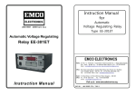
Instruction Manaual
for
Automatic
Voltage Regulating Relay
Type EE 301-M
EMCO ELECTRONICS
Works : Unit No. 13, "Kedarnath", Tungareshwar Industrial Complex No. 1, Village Sativali,
Vasai(E), Dist : Thane - 401208. Tel.:(0250)2481783 / 1804, Fax : (0250)2481087,
Email : [email protected]
Office : 302, Vasan Udyog Bhavan, Sanapati Bapat Marg, Opp. Phoenix mill / Big Bazar,
Lower Parel(W), Mumbai - 400 013. Tel.:(022)24902283/24923183,
Fax : +91-022-24951024, E-mail : [email protected]
South : 15, Wood Street, (1st Floor),Richmond Road, Bangalore - 560 025
Office Tel : (080) 557 0215
Fax : +91-80-556 6606
E-mail : [email protected]
Visit us at : www.emcoelectronics.org
DOC No. : MK 01 - 702 / ISS.2
CONTENS
Sr. No.
TITLE
PAGE No.
I
INTRODUCTION
1
II
GENERAL DESCRIPTION
1
III
SPECIFICATIONS
1
IV
FAMILIARIZATION WITH INDICATIONS / CONTROLS
2
V
OPERATION INSTRUCTIONS
4
VI
TYPICAL INSPECTION PROCEDURE
5
VII
FUNCTIONAL DESCRIPTION OF VARIOUS MODULES
6
VIII
FAULT FINDING PROCEDURE
7
IX
LINE DROP COMPENSATOR
11
X
SUPERVISORY ALARMS OPTION
13
XI
LIST OF DRAWING & RECOMMENDED SPARES
14
XII
WARRANTY
15
XIII
FAULT REPORT FORM
19
I
INTRODUCTION
EMCO’s Solid State Voltage Regulating Relay Type EE 301- M is used for regulating the
secondary voltage of power transformer with on-load tap changer . The required dead-band
settings are set by setting the Nominal value and L & R levels independently. The Time Delay
setting on the front panel eliminates the relay operations for momentary fluctuations of the
regulated voltage, thus reducing the number of operations of the tap changer.
When the regulated voltage falls below the specified Under Voltage limit, the control relays are
automatically blocked i.e. there is no voltage correction, and a pair of relay contacts is made
available for alarm.
The relay uses all solid state circuitry which increases its reliability and life. The relay is of
modular construction and the PCBs are plug-in type and can be easily withdrawn from the
instrument for servicing without disturbing the unit. The O/P, I/P connections are made through a
polarised connector which enables easy removal of the instrument without disturbing the control
wiring. However all normal precautions/care in handling/storage should be observed as for a
sensitive electronic instrument.
II
GENERAL DESCRIPTION
EMCO ‘s Solid State Voltage Regulating Relay Type EE 301-M is designed for maximum
operational simplicity for regulating the secondary voltage of power transformer with on-load tap
changer. The dead-band (bandwidth) can be set by setting the nominal value (NVA) to the required
value (110V + 10%) and then setting the L & R limits around the NVA within 0.5V to 5V.
The desired time delay can be set on the front panel and the control action will take place only if
the voltage continues to remain outside the dead-band after the time delay has elapsed. For
voltage corrections requiring more than one tap change, time delay is initiated again before further
tap change. The relay is reset automatically after the voltage is brought within the selected
deadband. The time delay is effectively reduced to provide a voltage time integral response of the
regulator for repeated short duration voltage fluctuations on the same side of the dead-band.
Operation of the Raise Control Relay is automatically inhibited when the voltage falls below the
specified under voltage limit or it fails. One pair of normally open relay contacts are provided to
effect the tap change during Raise and Lower operation and to trigger an alarm in case of Under
voltage / P.T. fail conditions.
III
SPECIFICATIONS :
Auxiliary Supply
PT Supply (Requlated Voltage)
Sensitivity (Dead Band)
and Nominal value Range
:
110V / 230V AC + 15% 50Hz, 15VA.
:
:
110V + 10%, 50Hz, 1.5 VA.
1. Nominal value adjustable (NVA) between
+10% of 110V and readable on DPM.
2. ‘L’ setting adjustable between 0.5V to 5V above
the NVA and readable on DPM.
3. ‘R’ Setting adjustable between 0.5V to 5V
below the NVA and readable on DPM.
4. Actual PT voltage also readable on DPM.
1
IV.
Time Delay Setting
:
Fixed (Voltage independent) Time Delay continuously
adjustable from 10 to 120 seconds.
Time Delay Resetting
:
Instantaneous resetting with voltage deviation
occurring in opposite direction.
Under voltage Blocking
:
Internal blocking at 80% of NVA. Restoration at 85%
of NVA
Control Relays
:
One pair of normally open potential free contacts of
rating 5A at 250V AC or 24V DC resistive load for
each Lower, Raise and Under voltage control relays.
Control Operation
:
Single Pulse operation with 2 seconds (approx.)
on-time.
Operating Temperature
:
0° - 45° C.
Overall Size
:
378 x 146 x 260 mm (HxWxD)
Mounting Details
:
Panel cutout - 330 x 135 mm,
with mounting holes (1/4" Æ x 4 Nos.)
@ (360 x 100) + 2mm
Weight
:
5kg Approx.
Options
:
1)
Line drop compensator with resistive and reactive
compensation of either polarity upto 20% and
suitable for operation with 1A/5VA current
Transformer.
2)
Normally closed “Auxilliary Supply Fail” relay
contacts.
3)
Normally open “Control Fail” relay alarm contacts
in case of control failure (i.e. in case of continuous
‘L’ or ‘R' command for more than 15 minutes).
4)
User defined settings for PT Supply, Time Delay
& Undervoltage Blocking
FAMILIARIZATION WITH VARIOUS INDICATIONS / CONTROLS :
A. INDICATIONS
1. Auxiliary Supply “ON”
:
DPM digits light.
2. ‘L’ Lamp
:
‘ON’ whenever the PT Voltage exceeds the 'LOWER
VOLTS’ set limit.
3. ‘R’ Lamp
:
‘ON’ whenever the PT voltage falls below the ‘RAISE
VOLTS’ set limit.
4. UV/PT FAIL Lamp
:
'ON’ whenever the PT Voltage falls below the factory
set Under Voltage limit i.e. below 80% of the Nominal
voltage. This lamp will turn-off only when the PT volt
age raises above 85% of the Nominal voltage value.
This lamp will be ‘ON’, when P.T. supply fails.
2
B.
5. 'LR' Lamp
:
'ON' When Lower Relay is energised.
6. ‘RR’ Lamp
:
‘ON’ When Raise Relay is energised.
7.‘TEST’ Lamp
:
‘ON’ When instrument is in “TEST” mode.
1. Power - ON (S1)
:
This is a toggle switch which when’ON’ supplies
Auxiliary Voltage to the instrument.
2. 'R’ Set (C1)
:
This is a variable control varying from 0.5V to 5.0V below
NVA setting. This control sets the (lower limit of the PT
voltage below which if the voltage reduces, then
corrective action will be taken by the instrument. The
setting is to be read on DPM.
3. 'NOM’ Set (C2)
:
This is a variable control to set the Nominal value of
PT voltage varying between + 10% of 110V. This set
ting becomes the reference level around which L & R
setting can be varied. The setting is to be read on the
DPM.
4. 'L’ Set (C3)
:
This is variable control, varying from 0.5V to 5.0V
above NVA setting. This control sets the upper limit of
the PT voltage beyond which if the voltage rises,
corrective action will be taken by the instrument. The
setting is to be read on DPM.
5. Time Delay (C4)
:
Corrective action takes place only after the Time Delay
as set by this control has elapsed and the PT Voltage
continues to ramain outside the set Lower or Raise
limits (but does not fall below the UV limit).
6. Test/Normal Switch (S2)
:
It selects the Test or Normal mode of operation. In the
Test mode, PT Voltage is simulated internally & can be
varied through the Test Control on the front panel. An
LED indication is provided to indicate that the
instrument is in Test mode. In the Test mode, the
control relays are “cut off” so that undesired operation of
OLTC is prevented during testing. The voltage is
monitoredon the DPM in PT I/P position. In the Normal
mode extemal PT voltage gets connected to the
instrument. This switch must be kept in ‘’Normal” mode
when the instrument is in use.
7. Test Voltage Control (C5)
:
Simulates PT I/P in Test mode and can be varied
from OV to 150V AC.
8. Selector Switch (S3)
:
Selects the voltage setting to be monitored on fhe DPM.
It also enables the PT voltage to be read on the DPM.
CONTROLS
3
NOTE : Before connecting Aux. Supply & PT Supply to the AVR Relay, Check-up
following points.
A)
Mechanical Damage : Remove the front acrylic cover by loosening the
thumbscrews & check for any mechanical damage to the unit.
B)
Check all plug-in modules : Open the botton panel & check M1 , M2, M3 &
M4 for any damage. Insert them fully inside, to avoid problems due to loose
contact.
C)
Aux fuse & P.T. fuse : Note that Aux. fuse is 300mA (20mm) & P.T. fuse is
100mA (20mm). Do not interchange these fuses. Check them & replace with
good ones if required.
D)
Close the lower bottom panel.
V. OPERATING INSTRUCTION :
1.
Connect the PT & Auxiliary Supply to the appropriate wires (3,4) and (1,2)
respectively, of the rear panel connector as per Drg. No. 01-MD-30. In case
separate Auxiliary supply is not available, then the same PT supply can be
connected to both the PT & Auxiliary terminals. Check whether the Normal/Test
switch is in the Normal mode.
2.
UNDER VOLTAGE BLOCKING :
This is factory set at 80% of the Nominal voltage. Note that between Blocking
and the Release (Restoration), a hysteresis of 5% has been provided i.e. if the
PT voltage falls below 80% of the Nominal value limit, UV Relay will operate
and block the control action (i.e. RAISE would be inhibited). However, if the
voltage rises again the RAISE control continues to remain inhibited till PT voltage
reaches 85% of the Nominal voltage. Blocking (80%) and Restoration (85%)
are factory set values, unless the customer has specified other values.
3.
TIME DELAY :
This is a variable control with variation from 10 sec. to 120 sec. The actual
setting can be made as required. The corrective action will take place only after
the set Time Delay interval is elapsed provided the voltage deviation persists
even after the set Time Delay and that the relay is not operating in UV mode.
NOTE :
4.
Please note that for the operational safety, RAISE and LOWER relays are
interlocked and hence OLTC will never receive two opposite commands
simultaneously.
CONTROL RELAYS :
Connect the respective Lower, Raise and Under voltage NO contacts to operate
the respective contactors.
4
VI. TYPICAL INSPECTION PROCEDURE :
1.
Connect 110V/230V A.C. Aux. supply to pins (1,2) of the rear panel connector.
2.
Turn on the instrument by putting power switch to ‘ON’ position.
3.
Make the following settings by changing selector switch :
NOMINAL VALUE
110V
LOWER VOLTS Setting 112V
RAISE VOLTS Setting
108V
TIME-DELAY Setting
30 Sec.
%R & %X Setting
‘0’ %
(in case of relay with LDC)
4.
Put the Test/Normal Switch to Test mode and selector switch to PT I/P position.
5.
Increase test-control to read PT = 110V.
6.
Note that under this condition all the lamps viz. L, R, LR, RR, & UV are OFF.
A. LOWER VOLTS OPERATION CHECK :
1.
Increase PT supply by the Test control above 112V (at least 112.5V), ‘L’ Lamp
should immediately turn on.
2.
The ‘LR’ Control pulse will come on only after 30 sec. from the instant of tuming
on of ‘L’ lamp. The control pulse will remain ‘ON’ for 2 sec., after which the Time
Delay of 30 sec. will restart and the control pulse will come again for 2 secs.
and the cycle is repeated.
B. RAISE VOLTS OPERATlON CHECK :
1.
Reduce PT Supply by the Test control•below 108V (at least 107.5V), but ensure
that it is above UV limit (88V). ‘R’ Lamp should turn ‘on’ immediately.
2.
The ‘ RR’ control pulse will come on after 30 sec. from the instant of turning on
of ‘R’ Lamp. The control pulse will remain on for 2 sec. after which the T.D. is
initiated again. After another 30 sec., the control pulse will come again for 2
sec. and the cycle is repeated.
NOTE:
The relays are cut off in the Test mode of operation to prevent any undesirable
operation of the OLTC during testing. However, the lamp indications will
indicate the operation of the relays. For checking the relay contacts, the PT
I/P should be connected through the rear panel connector (pins 3,4) and
Test/Normal switch put in Normal mode. The PT I/P can be varied externally
and the relays are checked as above. The respective N0 contacts will close.
C. UNDER VOLTAGE/PT FAIL OPERATION CHECK :
1.
Reduce the PT supply below 88 V, UV lamp will turn-on immediately (under
this condition R lamp wiil also be ‘on’). but Raise control is inhibited.
2.
Raise the PT supply above 94V, UV lamp should turn off immediately.
5
3.
‘R’ lamp indication however shall remain on, if the PT voltage is still below the
Raise setting. The raise control pulse will come on after the set Time Delay.
4.
Disconnect extemal PT supply - the UV & R Lamp will turn on immediately. The
UV relay will operate. After restoration of PT supply, the lamp wiil turn ‘off’ & UV
relay will be deenergised.
FUSE REPLACEMENT :
1
After switching power-on, the DPM indication must come. If it does nof come,
check whether AUX. fuse on the front panel is properly tightened. If the
instrument still does not work, unscrew the fuse & check if it is open. Replace
it by another fuse of 300mA (20mm).
Once again ensure that the fuse is not loose. The instrument should turn on
now. If the fuse keeps on blowing repeatedly or the instrument does not work
inspite of good fuse, proceed to identify the faulty PCB as given in fault finding
procedure VIII.
2
Connect the PT supply and put the Test/Normal switch in Norrnal position. If
the Instrument is turning on but you are continuously getting 'R’ and ’UV’
indication, check whether PT fuse is loose. If the condition persists even after
tightening PT fuse, remove the same and replace by another 100mA (20mm)
fuse. If ‘UV’ and ‘R’ indication still persist, proceed to identify the faulty PCB as
given in fault-finding procedure VIII.
VII. FUNCTlONAL DESCRIPTlON 0F VARlOUS MODULES :
1.
Mains Transformer : This trasnformer is mounted on the rear side railing. This
takes 230V/110V A.C. and steps it down to 19V, 12V, 5V, 10V A.C. voltages
required generating dc power.
2.
P.T. Transformer : This is mounted on PCB module M2 which steps down PT
input from 110V A.C. to 3.3V A. C. Which is used for sensing PT voltage.
3.
Power Supply Module M1 : This module generates +15V DC, -15V DC,
+5V DC & +5V DC (for DPM) required for circuit operation. Three pin regulator
ICs 7815, 7915, 7805 are used to give regulated +15V, -15V & +5V D.C.
Supplies. The four LEDs mounted on front side of module M1 indicate the
presence of these voltages. If all four LEDs of module M1 are glowing brightly &
voltages are as given in TABLE 1 (Page No.9) then this module is OK. If anyone
LED is not glowing or glowing very dim, then proceed as per step No.5 given in
fault finding procedure VIII.
4.
Analog Module M2 : The PT input is stepped down in the ratio 110/3.3. This
stepped down voltage is rectified. filtered and amplified by IC4 & IC5. This
voltage is used for comparison with reference voltage. IC3 generates regulated
+10V DC by taking +15VDC as input. This 10V DC rs used as a reference
voltage for comparison. IC2 compares the input signal with L, R, UV set points
& generates appropriate L, R or UV signal which are passed on to module M3.
5
Digital Module M3 : This card receives L, R, UV signals from card M2. On
6
receiving any of these signals, it generates Time Delay followed by LR, RR & UV
commands for energizing appropriate relay.
6.
Relay Module M4 : In this module , relays for L, R, & UV commands are mounted
which are energized as per commands received from module M3.
7.
Digital Panel Meter : The main function of DPM is to display PT input, Nominal
setting, L, R settings through selector switch. This DPM operates on +5V supply
which is supplied by P.S. Module M1.
VIII. FAULT FINDING procedure :
Before proceeding to fault finding, be familiar with the functions of each module & various test
points on these modules. Study the nature of fault & try to visualise faulty module. Then Proceed step by step as follows.
Step-1
:
Check for any physical damage by opening front doors.
Step-2
:
Check the Aux. fuse (300mA) & PT fuse (100mA). If necessary, replace
them. (Do not interchange the fuses). Tighten them properly.
Step-3
:
Confirm that all four modules M1, M2, M3 & M4 are inserted fully in the
backside connectors & having proper contacts
Step-4
:
Connect 'Aux’ supply & PT supply & Switch ON the unit. If the unit does
not get switched ON, then check aux. switch.
Step-5
:
Open the bottom front cover. Check the four LEDs mounted on moduleM1.
If all LEDs are glowing brightly then module M1 is alright. If anyone of the
LEDs is not glowing or all LEDs are glowing very dim, then measure voltages
on the test points as given in table No.1. If the voltages are not as
expected, then remove other modules M2, M3 & M4. Measure the voltages
again (or confirm all 4 LEDs are glowing brightly). If voltages are not correct
then replace M1. If the voltages are correct without M2, M3, & M4, it means
M1 is alright but other module is over loading P.S. module. Insert M2, M3 &
M4 one by one and find out which module is loading. Replace the fautty
module. Confirm all D.C. Voltage are as per table No.1.
Step-6
:
Proceed to check M2 as follows :
Please note that M3 should also be there. Put the selector switch (S3) in
Nominal set position and vary the Nominal set control to read 110V
+ 10% on DPM. Set Nominal control to 110V. Now keep the selector switch
(S3) to ’R’ set position and vary ‘R’ set control to read 104.5V to 109.5V
on DPM. Set ‘R’ set control to 108V. Tum S3 to ‘L’ set position and vary ‘L’
set control to read 110.5V to 115.5V on DPM. Set ‘L’ set control to 112V. If any of
the settings are not obtainable, it means either front panel controls are
faulty or M2 is faulty. Replace M2. If problem still persists, then check front
panel controls (i.e. potentiometers for their open/short conditions). If
required replace them.
7
Step-7
:
Turn selector switch S3 to PT I/P position. Put NormaI/Test switch (S2) to
Test position. Vary the Test control in clockwise direction to read PT I/P on
DPM. If DPM does not read then measure AC Voltage at TP 3 w.r.t. GND on
M2. It should vary from 0 to 5V AC. with clockwise rotation of Test Control.
If the voltage is not coming, it means either S2 is faulty or 0-5V wdg. of
Mains Tx. is open or Test control (CS) is faulty. If the voltage is,OK, it
means M2 is faulty.
Step-8
:
Vary the Test control & read PT I/P on DPM. When PT I/P is less than 88V
(i.e. 80% of nominal set-UV levels), then the UV indication alongwith ’R’
indication should come. Increase the voltage above 93.5V (85% of nominal
set-UV restoration), then UV command goes “off”. However ’R’ command
remains “ON”. Increase PT I/P Voltage Slightly more than 108V, ‘R’ will go
off. This is B.W. Condition. Increase PT I/P Slightly more than 112V, ’L’
indication should come. If the UV, L & R indications are coming as above
that means M2 is 0K. If not change M2 After changing M2 still problem
persists then check M3.
Step-9
:
Proceed to check M3 as follows:
Set Time Delay (TD) control to 30 sec. Vary the test control to get ‘L’
condition. Measure time from which ‘L’ indication comes to the time ‘LR’
indication comes. The ’LR’ indication will remain ’ON’ for 2 sec. afterwhich
once again TD’ is initiated.
(The ‘TD’ indication is provided on M3) Similarly get ‘R’ condition, “RR”
should come after set Time Delay. If ‘LR’ & ‘RR’ indications are not
coming after set time delay, it means M3 is faulty. In the ‘Test’ mode, the
supply to the relays is cut. Offer Hence relays will not operate only
indications for ’LR’ & ’RR’ will come.
Step-10
:
Put switch S2 to Normal position. In this position the PT I/P comes
through rear panel (actual PT Voltage). Vary PT I/P and read on DPM. If
DPM does not read, measure AC Voltage at TP3 ON M2. It should be
around 3.3V AC for 110V AC PT I/P. If this voltage is not coming, it means
either S2 is faulty or PT fuse is faulty or PT transformer on M2 is faulty.
Step-11
:
To check relay module M4, vary PT I/P to get ’L & R’ conditions in
Normal mode & confirm that Lower relay and Raise relay are operating,
by checking continuity at rear terminals. If “RR” & “LR” indication are
coming but relays are not operating then check 15V supply to relay
Module M4 or check S2. If relays are operating but 'NO’ contacts are not
closing means relay contacts are faulty. Ensure that Relay contacts are
not connected to the Tap-Changer Replace M4.
(In above description, it is assumed that DPM & LEDs are OK).
8
Step-12
:
TO CHECK DPM
Measure following voltages on DPM back side connector.
bet ‘0’ & 5V = 5V DC
bet Lo & Hi = 10V DC (approx) at 110 PT I/P
DPM should indicate 110.0V
If these Voltages are present and still DPM is not showing anything or
some segments or digits are not glowing it means that DPM is faulty,
replace it.
For LEDs (mounted on front panel) : If M2 & M3 are OK and still LEDs
are not glowing for proper conditions then the LED itself may be defective,
replace it.
Table No.1 On Module-M1
Test Points
Expected Voltage
betTP1 &TP3
+15V + 0.5 V
betTP2&TP3
-15V + 0.5 V
betTP4&TP3
+5V + 0.25V
betTP5&CapC8-ve
+5V + 0.25 V
On Module - M2
Bet TP3 (on M1) & TP3 (on M2)
(For PT I/P = 110VA.C.)
3.3VAC + 0.2%
Bet TP4 (on M2) & TP3 (on M1) (For PT input 110V
A.C.)
+10VDC + 0.2%
(should vary with
PT input)
TP7 (on M2) & TP3 (on M1) (For Nom Set = 110V)
+10V DC
Note : All the Voltagesare measured w.r.t. TP3 on module M1 .
9
Potentiometer P1 on Module M2 is for adjusting UV settings. Factory set value is
80% of nominal value. It can be adjusted upto 50% of nominal value.
Potentiometer P3 on Module M2 is for adjusting +10V DC at TP4 for PT input of
110V A.C.
NATURE OF FAULT
PROBABLE CAUSES
Unit not getting 'ON'
Check fuses, 'Power On Switch Connections
to rear connector are OK. Check M1. If faulty,
replace it.
UV indication 'ON'
Check PT supply, PT Fuse and M1.
If all are OK, if faulty replace.
DPM reads '000' in all position of
selector switch S3
Checked M2, if faulty replace.
No Variation in DPM reading by varying
R, L set controls or normal set controls
Check M1 & M2, if faulty replace.
L or R or UV indications not coming after
varying PT input beyond dead band
settings.
Check M1. If OK. M2 must be faulty.
L or R indication remains permanently 'ON' Check M2. If OK, M3 is faulty.
LR or RR not coming after varying PT I/P
If M1 & M2 OK then M3 faulty.
voltage and waiting for the set time delay.
Time delay LED on module M3 remains
'ON' permanently
M3 faulty.
Time delay is not as per set value
Time delay dial might have shifted. Adjust
the setting of T.D. as follows. Slightly loosen
the Knob and rotate T.D. control fully anticlockwise to match the dot with the starting
dot below Tighten & check the Time Delay
value for 30 secs. Readjust slightly if
necessary.
LR & RR commands coming but OLTC
not operating
If M1, M2 & M3 are OK and if Test/Normal
switch is in Normal mode then replace M4.
If problem still persists then check-up control
panel wiring.
'LR' or 'RR' commands remain "ON"
permanently
If M1 OK, M2-OK then M3 faulty.
10
IX. LINE DROP COMPENSATOR
I.
DESCRIPTION
The Line Drop Compensator is an optional unit designed to match with the Automatic
Voltage Regulating Relay Type EE-301 M. The unit is housed in the same enclosure.
(Plug-in type module)
The LDC unit cannot be mounted afterwards at site but has to be ordered at the time of
placing an order.
The Voltage at the generating end and at the receiving end are not the same due to the
drop across the line. The LDC is used to compensate for this line drop, and the amount
of compensation required is calculated as a % of the Nominal voltage knowing the length
of the line, its resistance/unit length, its reactance/unit length and the rated current, and
set on the front panel.
The line current is stepped down to 1Amp and fed to the LDC unit. The resistive and
reactive drops are simulated by having 90° phase-shifted voltages and their polarity is
selected by polarity switches. The net compensation is then summed with the stepped
down PT voltage.
II.
III.
SPECIFICATION :
Resistive Compensation
Reactive Compensation
Input rated current
Powerconsumption
Accuracy
Max. Over current
PolaritySelection
:
:
:
:
:
:
:
0-20% of the regulating value continuously adjustable.
0-20% of the regulating value continuously adjustable.
1 Amp, 50 Hz.
5VA max. at 1 Amp.
10%.
50% of rated current (1.5Amp).
Both positive and negative Compensation.
OPERATING AND CONNECTION INSTRUCTION:
Connections to the LDC unit are made through the rear panel terminals (5,6). The line
current is stepped down to 1Amp. 50 Hz and fed to the LDC. The net compensation
is fed to the AVR ckt. internally.
The required amount of %R and %X compensation can be set on the front panel of the
LDC. The polarity select switches will provide both positive and negative
compensation.
The %R & %X settings can be calculated from following formulae.
%X = Ö3ILxXL x 100
VL
%R = Ö3ILxRL x100
VL
Where IL = the primary rated current of the line.
11
VL = the voltage between lines of power transformer.
XL = the line reactance in ohms/phase.
RL = the line resistance in ohms/phase.
The LDC simulates the resistive & reactive drops across the line. The %R setting gives the
resistive drop which is in phase with line current. The polarity switch VR selects whether the
drop has to be added or subtracted from PT Voltage.
In +VR position this voltage is subtracted from the PT voltage so that its effect on AVR is to
Raise the voltage equal to the resistive drop to make the voltage at the load equal to nominal
tvalue. In -VR position drop is added & its effect on AVR is to ‘LOWER’ the voltage. In normal
use, VR switch is kept on + posiiion.
The % X setting gives the reactive drop across the line. This drop is in phase quadrature to
the line current. The +VX gives lagging compensation and -VX gives leading compensation.
Since the reactive compensation is in quadrature, its effect on AVR magnitude is very less.
However, its effect is observable for power factors bet. 0.5 & 0.7 and is similar to VR compensation i.e. +VX raises the voltage & -VX Lowers.the Voltage.
The PT I/P to the AVR is internally stepped down to 3.3V corresponding to 110V. The vector
sum of resistive & reactive drops i.e. LDC 0/P is added vectorially to the stepped down PT
voltage to get the sense voltage at load end.
TESTING OF LDC
a)
Feed 110V PT to AVR and keep R = 105 & L = 115.
b)
Keep %R & %X setting of LDC to minimum position (i.e.U%)
c)
Now the AVR is in dead-band condition. Feed 1A current through the terminals 5 & 6 on rear
panel.
d)
Keep both polarity switches to +VR & +VX position.
e)
Increase %R compensation trom 0 to 20%, 'Raise’ indication should come.
f)
Put polarity switch to -VR position, “Lower” indication should come.
g)
Bring back %R control to zero position.
h)
Set R & L settings to 108V & 112V. lncrease % X control from 0 to 20%, Raise indication
should come. Put polarity Switch to -Vx position, Lower indication should come.
(N.B.) -
This can be observed only for a power factor of 0.5 to 0,7. For lower P.F. effect is not
observable.
Note :-
If above tests are not ok, then interchange CT connections at 5 & 6 and carry out
same tests.
CALIBRATION CHECK OF %R
a)
Assuming current in phase with voltage (i.e. P.F. = 1)
set L = 115V & R = 105V, %R = 0 & %X = 0.
Check operation of AVR without feeding 1Amp current to LDC.
12
b)
Note down values at which R & L indications come. Let us say they come at 105V&
115 respectively.
c)
Pass 1 Amp current through LDC and increase %R setting to 5%. Put polarity switches
in + position.
d)
Vary the PT Voltage and note value at which R & L indications come. They should be
5.5V above set Values, i.e. R = 110.5V & L = 120.5.
e)
Put VR switch to -Ve position and vary voltage and check the voltages when R & L
indication come. They should be 5.5V below the set values i.e. R = 99.5 & L = 109.5.
Similarly check for 10% compensation. The difference will be +11V i.e. levels will be
L = 126V, R = 116V, for +VR & L = 104, R = 94V for -VR.
f)
The %X Compensation cannot be checked, because of its small effect on AVR. If
above tests are not coming OK, then change LDC unit.
VERY IMPORTANT
1.
Do not remove LDC unit when C.T. current is flowing. (This action will make CT open
CKT and damage it).
Arrange to switch off CT current or short CT before removing LDC unit.
2.
When LDC is not to be used then both %X and %R dials should be kept at 0%. This
position will give 0 compensation. Do not remove LDC unit from relay as AVR will not
function without LDC unit inside.
X. SUPERVISORY ALARMS OPTION
Following Supervisory Alarms options also can be incorporated in the same Relay
EE 301- M, if required.
1)
Relay contacts to give alarm instantaneously when Auxiliary supply to the AVR Relay
fails.
2)
Relay contacts to give alarm if the regulated voltage remains outside the set dead
band for more than 15 minutes.
SUPERVISORY ALARMS
1)
This unit consists of one relay which operates on 110V A.C. It remains energised as
long as 110V A.C. (Aux supply) is present at Pin No. 1 & 2 of the AVR relay. When Aux
supply fails, this relay gets deenergised, the “NC” Contacts at pin No.7 & 8 can operate
the alarm.
2)
It also consist of a 15 minutes timer which starts counting as soon as the regulated
voltage goes out of the set dead band (either Raise side or lower side). If the regulated
voltage remains outside dead band for more than 15 minutes then a relay operates
which closes “NO”’ Contacts at Pin 15 & 16. These contacts can be used for “Control
fail” alarm. The operation of this control fail relay is indicated by a red LED marked
“CFR” mounted on front panel.
13
This control fail alarm will operate in following circumstances:
a)
failure of OLTC to raise or lower the taps.
b)
incoming voltage very high or very low i.e. beyond control of the transformer
and tap has reached either lowest position or highest position.
c)
Mal-functioning of A.V.R. Relay.
The supervisor in the sub station should take appropriate steps to remove the
above mentioned faults.
If the voltage returns in the set dead band within 15 minutes, the 15 min timer
resets automatically.
TESTING PROCEDURE
1)
Give Aux supply 110V A.C. to the A.V.R. Relay and check continuity at Pin No. 7 & 8.
It should show open. Remove Aux supply to the relay and check the continuity at Pin
No. 7 & 8, it should show short.
2)
CONTROL FAIL ALARM RELAY:
Make the dead band settings as desired. Change the PT voltage to get either R or L
indication. Keep the regulated voltage outside the set dead band; after 15 minutes
(approx. ). the control fail alarm relay will operate and will remain in energised condition
till the voltage returns to set dead band. This operation will be indicated by red LED
marked CFR mounted on front panel of AVR Relay. The relay contacts can be checked
at Pin 15 & 16.
Take the regulated voltage within set dead band. The control fail Relay will get
deenergised and the contacts at Pin 15 & 16 will again become open and LED will
stop glowing. Similarly this operation can be checked by taking regulated voltage on
other side of set dead band.
XI LIST OF DRAWINGS :
1.
2.
3.
Block Diagram
Front Panel View
Rear Panel View / Cutout
Dimensions/AVR connections
:
:
01-ED-25
01-MD-29
:
01-MD-30
RECOMMENDED SPARES :
1.
2.
3.
4.
5.
6.
7
Power supply Mdule M1
Analog Card Module M2
Digital Card Module M3
Relay Module M4
Digital Panel Meter (DPM)
Mains Transformer
LDC Module (in case of AVR with LDC)
14
WARRANTY
This product from EMCO ELECTRONICS is warranted against defects in materials and
workmanship for a period of 12 months from the date of despatch to the first
buyer/purchaser of this equipment, this being essentially limited by warranties given to
EMCO ELECTRONICS on the component used in equipment.
During the warranty period EMCO ELECTRONICS will at its option, either repair or
replace the product which prove to be defective provided the product has been used
with reasonable care and in accordance with the manuals/product specification.
Consequently this warranty shall also not apply to defects/damages in transit or
resulting from misbehaving, misuse, Unauthorised modifications or repairs operations
outside the environmental, electricai and/or other specification, improper or inadequate
maintenance of the product, or site conditions as required/recommended and
damages arising from accidental or abnormal causes.
The warranty period for items repaired/replaced shall not exceed then period for which
the equipment was originaliy warranted and also the liability of EMCO ELECTRONICS to
the purchaser shall not in any case, exceeds the original purchase price of the
equipment.
For warranty service or repair, the equipment must be returned to EMCO
ELECTRONICS securely packed on Freight paid basis and accompanied by a
certificate stating that the equipment is being returned for warranty repairs and also
note giving details of the purchase (Purchaser’s Name. and address, invoice No. and
Date of purchase) and details of the equipment failure. faults conditions, other useful
information to faciliate early repair/rectification or the equipment.
Return of the equipment duly repaired can be arranged on payment of the packing and
forwarding charges together with any cther taxes. duties, other miscellaneous expenses
incurred, altematively the purchaser may arrange to collect the equipment from EMCO
ELECTRONICS. In case the repairs are not covered under warranty, the charges tor the
same must also be paid before collection of the equipment.
Our engineer’s services are available at site for instruments during warranty or out of
warranty period, on chargeable basis. Details of which are available on request.
In the interest of development and improvement EMCO ELECTRONICS reserve the
right to amend without notice details contained in this publication. No legal liabilities
will be accepted by EMCO ELECTRONICS for any errors, omissions or amendments.
15
To,
EMCO ELECTRONICS
106, Industrial Area,
Sion (East), Mumbai-400 022.
Tel. : 4096731 / 82
From :
"
FAULT REPORTING FORM FOR AVR EE301-M
Please fill this form when sending the faulty AVR / Module for repairs. This will help us to serve you better.
AVR Serial No. :_________________
Supplied By :____________________________________
Working Since :__________________
Nature of problem :____________________________________________________________________________
____________________________________________________________________________________________
"
____________________________________________________________________________________________
Settings on AVR : L SET=_________R SET=_________NVA=__________TD=_________DPM Rdg. =___________
Check Auxillary & PT Fuses before proceeding.
Please observe the following on the faulty AVR & tick the appropriate box.
Put AVR in "TEST" Mode & vary the "TEST CONTROL" (TC.) Potentiometer.
CUT HERE & POST
Yes
No
1. DPM rdg. varies with TC.
2. 'R' LED glows when DPM rdg.<R SET
3. 'RR' LED pulses after TD.
4. 'L' LED glows when DPM rdg.>L SET.
5. 'LR' LED pulses after TD.
6. 'UV' glows for UV condition.
7. ALL LEDs are off in Deadband condition.
"
Put AVR in 'NORMAL' Mode & check respective relay contacts.
8. 'RR' contacts close & open for step 3.
9. 'LR' contacts close & open for step 5.
10 'UV' contacts close (& open when UV restored) for step 6.
11. Any of the LR / RR / UV contacts permanently closed.
12. All 4 LEDs on M1 Module ON.
"
13. T1D LED on M3 Module loggles ON/OFF for continuous LR/RR conditions.
*Note : Open bottom front plate to observe the LEDs.
14. OPTIONS : LDC / CFR / AUXILIARY FAL operating properly.
15. Any other information :________________________________________________________________________
____________________________________________________________________________________________
____________________________________________________________________________________________
____________________________________________________________________________________________
NAME OF TEST ENGINEER :_____________________
SIGN. :___________________
DATE :__________________
DOC No. : SR 01-401/ISS-1