1
Operating Instructions SIPLUS CMS1000
3.2
Sensor
3.2.1
Installation Position, Dimensions
Installation Position
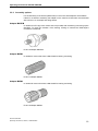
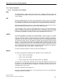
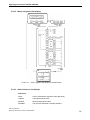
The Sensor should be fixed radial to the rotating axis of the motor and as close as possible near the bearing in the load-zone that shall be monitored.
The Sensor is only allowed to be fixed on safe grounded metal parts.
The Sensor cable must only be installed in rooms with a maximal environmental temperature of +90º Celsius. Joining the cable to the crankcase is forbidden.
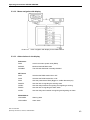
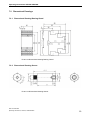
Dimensions
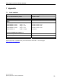
Chart 2
Dimensions
Dimensions (mm)
Installation length
64 mm
Diameter
22 mm
Notice
- The Sensor must be fixed form-closed, to assure the correct transmission of the vibration.
- The Sensor must not be mounted on curved or coated surfaces
- The signal line should be as short as possible
- Ensure that there are no additional changeover of material besides bearing and bearing carrier
- Oscillating parts of housing are not permitted as measurement position
- Measurement should proceed in direction of load
- Mounting should be done in direction of highest velocity of vibration. As far as there are no measurement or data available mounting
o
o
should be done in 135 or 225 from A-side
- Very low diagnostic characteristic values might be caused by wrong measurement position or faulty installation of the sensor
- Measurement of RMS should not be done with sensor mounted on exposed SPM-nipple
- Changes in the setting-up area of the motor can influence the diagnostic characteristic values.
SIPLUS CMS1000
Operating Instructions, 02/2011, A5E01653960
15