1
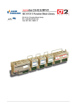
Description
PLC Interface
FEDFED-CEC
FEDFED-CECCAN
Digital and analog
I/O Module
FEDFED-UIM
760 372
1108a en
Weitergabe sowie Vervielfältigung dieses
Dokuments, Verwertung und Mitteilung seines
Inhalts sind verboten, soweit nicht ausdrücklich
gestattet. Zuwiderhandlungen verpflichten zu
Schadenersatz. Alle Rechte sind für den Fall der
Patent-, Gebrauchsmuster- oder Geschmacksmustereintragung vorbehalten.
The reproduction, distribution and utilization of
this document as well as the comunication of its
contents to others without express authorization is
prohibited. Offenders will be held liable for the
payment of damages. All rights reserved in the
event of the grant of a patent, utility module or
design.
Sin nuestra expresa autorización, queda
terminantemente prohibida la reproducción total o
parcial de este documento, así como su uso
indebido y/o exhibición o comunicación a terceros.
De los infractores se exigirá el correspondiente
resarcimiento de daños y perjuicios. Quedan
reservados todos los derechos inherentes, en
especial los de patentes, de modelos registrados y
estéticos.
Toute communication ou reproduction de ce
document, sous quelque forme que ce soit, et
toute exploitation ou communication de son
contenu sont interdites, sauf autorisation écrite
expresse. Tout manquement à cette règle est
illicite et expose son auteur au versement de
dommages et intérêts. Tous droits réservés pour le
cas de la délivrance d'un brevet, d'un modèle
d'utilité ou d'un modèle de présentation.
È vietato consegnare a terzi o riprodurre questo
documento, utilizzarne il contenuto o renderlo
comunque noto a terzi senza esplicita
autorizzazione. Ogni infrazione comporta il
riscarimento dei danni subiti. Sono riservati tutti i
diritti derivanti dalla concessione di brevetti per
invenzioni industriali di utilità o di brevetti per
modelli ornamentali.
Detta dokument får inte utan vårt tillstånd
utlämnas till obehöriga eller kopieras, ej heller får
dess innehåll delges obehöriga eller utnyttjas.
Överträdelse medför skade- ståndskrav. Alla
rättigheter förbehålls, särskilt rätten att inlämna
patent-, bruksmönster- eller mönsteransökningar.
Copyright:
© Festo AG & Co. KG,
Postfach
D-73726 Esslingen
Phone:
+49 / 711 / 347-0
Fax:
+49 / 711 / 347-2144
e-mail:
[email protected]
Internet:
http://www.festo.com
Original: en
Version: 1108
Contents
1
Festo FED-CEC / FED-CECCAN ............................................................................................ 3
1.1 Overview ........................................................................................................................... 3
1.1.1
FED and CoDeSys Control Solutions ............................................................ 3
1.1.2
System Configurations ................................................................................... 4
1.1.3
Requirements and Limitations ........................................................................ 5
1.2 Getting Started .................................................................................................................. 6
1.2.1
Installing the FED-CEC Control Module......................................................... 6
1.2.2
Control Module Diagnostic ............................................................................. 6
1.2.3
Installing the FED-UIM I/O module ................................................................ 7
1.2.4
I/O Module Diagnostic .................................................................................... 9
1.2.5
Installing the CoDeSys provided by Festo Programming System ................. 9
1.2.6
Setting-up the Communication ....................................................................... 9
1.3 HMI Programming ........................................................................................................... 13
1.3.1
Enabling the Internal Controller CoDeSys ................................................... 13
1.3.2
The Tag Editor .............................................................................................. 16
1.3.3
Using the RDA .............................................................................................. 28
1.3.4
Programming the Mailbox ............................................................................ 29
1.3.5
Alarms .......................................................................................................... 29
1.3.6
Alternative Approach to RDA, Alarms and Mailbox ..................................... 30
1.3.7
Transferring Data with the Internal Controller .............................................. 31
1.3.8
FED Communication Diagnostic .................................................................. 31
1.4 Using the Internal Controller ........................................................................................... 32
1.4.1
Target Settings ............................................................................................. 32
1.4.2
System Library Support ................................................................................ 34
1.4.3
System events Support ................................................................................36
1.4.4
Setting-up the PLC Configuration ................................................................ 36
1.4.5
PLC Programming ........................................................................................ 39
1.4.6
PLC Project Upload ...................................................................................... 39
1.5 I/O Boards Overview and General Information ............................................................... 39
1.5.1
Diagnostic information .................................................................................. 39
1.6 FED-UIM ......................................................................................................................... 40
1.6.1
Overview and Technical Specifications........................................................ 40
1.6.2
CoDeSys Support for FED-UIM ................................................................... 50
1.6.3
Configuration of Analog Inputs ..................................................................... 50
1.6.4
Configuration of Analog Outputs .................................................................. 52
1.6.5
Digital Input and Digital Output Configuration .............................................. 54
1.6.6
Counter/Timer Inputs.................................................................................... 54
1.6.7
Diagnostic ..................................................................................................... 57
FED-CEC FED-UIM Description
2
1
1.1
Festo FED-CEC / FED-CECCAN
Overview
This manual describes the FED HMIcontrol system based on the CoDeSys control
software.
The documentation covers:
FED-CEC / FED-CECCAN control modules factory-loaded with CoDeSys run-time,
FED local I/O subsystems
CANopen distributed I/O interface.
This manual is not intended to be a reference for CoDeSys programming. If you
need a CoDeSys programming manual please refer to the appropriate
documentation.
FED-CECCAN has no Ethernet interface. It can be used in all FEDs with integrated
Ethernet interface (FED-400, FED-550, FED-700, FED-1000, FED-2000, FED-5000).
For Panels which have no integrated Ethernet interface the FED-CEC has to be
used.
In the documentation only the synonym FED-CEC is used.
1.1.1 FED and CoDeSys Control Solutions
At the core of HMIcontrol there is the FED-CEC PLC module. Control modules
based on CoDeSys are compatible with all FED panels (except for FED-40 models)
with firmware 5.12 or higher.
FED-CEC Ethernet interface supports also basic TCP/IP Ethernet connectivity for
FED and CANopen master interface
The FED-CEC modules physical memory configuration is described in Table 1. The
table refers to CoDeSys firmware version V4.01K and above.
Data Memory
1MB
FED-CEC / FED-CECCAN
Code Memory
1MB
Table 1
They all have a typical scan time measured for the execution of BOOL instructions
written in IL language of 350 µs / K .
Note
The CoDeSys implementation on FED-CEC modules correspond to a single-task model with
no multithreading; the CoDeSys kernel has a system execution time fixed at operating
system level, to 10ms; this means that the fastest possible reaction on I/O image is limited
to 10ms.
CoDeSys is the complete development environment for the FED-CEC PLC modules.
CoDeSys offers the PLC programmer a simple approach to the powerful IEC
languages.
FED-CEC FED-UIM Description
3
The original documentation of CoDeSys will be installed when the software is
installed. The available documentation includes a clear and detailed presentation
of the software and contains also a useful “First Steps with CoDeSys” that should
be your first guide in getting confidence with the system.
The main technical data of the FED-CEC control modules are shown in the table.
CPU
Clock speed
Program Flash memory
Data Flash Memory
SDRAM memory
CPU supervision (Reset, Watchdog)
Interface
32 bit MIPS RISC processor
24Mhz
4MB
16MB
8MB
Yes
Ethernet 10BASE-T (only FED-CEC)
CAN interface with optical isolation
Table 2
1.1.2 System Configurations
You can apply the HMIcontrol systems in different configurations.
1.1.2.1 Compact Stand-alone Controller
The HMIcontrol system can be used to build very compact standalone HMI and
PLC systems. Input/output is available via the FED-UIM internal modules.
Figure 1
1.1.2.2 Controller with Distributed I/O
A built-in fieldbus interface is provided with the HMIcontrol modules.
Configurations with local and distributed I/O are possible.
FED-CEC FED-UIM Description
4
Figure 2
1.1.2.3 HMIcontrol Connectivity
An HMIcontrol system still offers the same connection capabilities of the FED
products. Control capability can be combined with connection to a conventional
controller (PLC).
Figure 3
1.1.3 Requirements and Limitations
The following firmware and software versions are required to work with the
CoDeSys HMIcontrol systems:
Version
6.03 or higher
5.12 or higher
2.3.2 or higher
FED Designer
FED Firmware
CoDeSys
Table 3
All the FED units have only one slot available for the communication or control
module and, if one iPLC module is used, it is no longer possible to plug one
additional communication module.
Note
The current implementation of CoDeSys on FED-CEC does not include drivers for Ethernet
distributed I/O.
FED-CEC FED-UIM Description
5
1.2
Getting Started
The following chapter describes the basic steps to follow in order to get
HMIcontrol running on the FED-CEC control modules.
1.2.1 Installing the FED-CEC Control Module
The FED-CEC Control Module must be installed in the socket available for the
optional Communication Modules.
The Control Module must be installed with the panel powered off. Once the power
supply is connected again the FED firmware will recognize the new module.
Follow this procedure to install the module in the operator panel:
1 Turn off the operator panel.
2 Remove the rear cover.
3 Plug the module in the slot with red connectors and make sure the
connectors are properly latched.
4 Re-install the rear cover.
5 Mount back the rear cover.
6 Stick in the area “B” the label indicating the type of module that has just
been plugged in.
Figure 4
1.2.2 Control Module Diagnostic
The System Menu of FED provides some basic diagnostic information on the
operation of the communication and control modules.
To view the diagnostic information:
1 Make sure the operator panel is in Operation Mode
2 Recall the System Menu
3 Scroll down the display to show the bottom row of the page
4 The diagnostic information will be shown as in the example below:
FED-CEC FED-UIM Description
6
SCMxx 0 H160 X130 OK
SCMxx
type of module
xx=05 FED-CECCAN
xx=12 FED-CEC
0 Hnnn Xnnn
internal version codes
OK
confirms the correct installation of the
control module.
5
FED-CEC firmware version can be read directly in System Menu; when the
SCMxx line is highlighted by the cursor, press the right arrow key to display
the version information.
FED-CEC modules always include the TCP/IP software usable for all Ethernet
based FED protocols.
Internal I/O modules are compatible with FED 500, FED 550, FED 1000, FED 2000
and FED 5000 models.
1.2.3 Installing the FED-UIM I/O module
Follow the procedure described below to install an internal I/O module.
1
2
3
4
5
6
7
8
9
FED-CEC FED-UIM Description
Turn off the operator panel and remove all cables.
Unscrew (but not remove) with the crosshead screwdriver the four screws A,
B, C, and D.
Remove the rear cover.
Insert the FED-UIM module
Fix the FED-UIM module with the two screws E and F.
Plug the FED-UIM internal flat cable connector in to the red connector and
make sure they are properly latched.
Remove the side protection inserts from the rear box.
Replace the rear cover, and fix the screws A, B, C, D.
Stick the labels indicating the pin assignment.
7
Figure 5
Figure 6
FED-CEC FED-UIM Description
8
Figure 7
1.2.4 I/O Module Diagnostic
The System Menu of FED provides some basic diagnostic information on the
operation of the internal I/O modules.
To view the diagnostic information:
1 Make sure the operator panel is in Operation Mode
2 Recall the System Menu
3 Scroll down the display to show the bottom row of the page
4 The diagnostic information will be shown as in the example below:
UIM05 0 H160 X130 OK
UIM05
type of module
0 Hnnn Xnnn
internal version codes
OK
confirms the correct installation of the
control module.
1.2.5 Installing the CoDeSys provided by Festo Programming System
Please take the FED Designer CD 6.06(05) or higher. Select the subdirectory
“CoDeSys pb Festo”. Start the installation of CoDeSys provided by Festo by
double click on the file “CoDeSys_pbF_vXXXX.exe” and follow the instructions.
1.2.6 Setting-up the Communication
The HMIcontrol system is composed by two subsystems, the FED Operator Panel
and the FED-CEC Internal Controller Module.
Programming both subsystems will be via the same serial communication link.
The FED-CEC modules offer, as a more efficient alternative, an Ethernet interface
that can be used for:
- Programming the internal PLC,
- communication with an external controller using a FED Ethernet communication
protocol and finally
- programming FED.
FED-CEC FED-UIM Description
9
The set-up of the CoDeSys communication is described in the following chapters.
1.2.6.1 Setting-up the Port for the CoDeSys Programming Software
Select “Online\Communication Parameters” in the CoDeSys programming
software. The “Communication Parameters” dialog will appear as shown in Figure
8.
The first time this dialog is opened, the user will be requested to specify the
channel for the connection with the PLC. Connection channels can be created with
the “New…” button.
Figure 8
When defining a new channel, the type and all the relevant parameters can be
defined in the dialog box shown in Figure 9.
The following options are possible:
FED-CEC/FED-CECCAN
FED-CEC FED-UIM Description
Serial (RS232)
TCP/IP (Level 2)
10
Figure 9
Default parameters for both serial port connection and Ethernet connection are
correct for operation with FED.
When defining the driver for Ethernet connection, the “Address” parameter shown
in Figure 10 must contain the IP address assigned to the FED-CEC module.
Figure 10
1.2.6.1.1 Setting the IP address in FED-CEC Control Modules
Setting the IP address of the module follows the standard rules for FED IP address
setup.
FED-CEC FED-UIM Description
11
1.2.6.2 Communicating with the Internal Controller
When FED does not contain a valid project, it stays in Configuration Mode; in this
situation the PLC port is assigned by default to the Internal Controller.
To program the Internal Controller when no project is loaded in the panel, use the
normal FED programming cable connected to the PLC port of the panel.
Note that the Ethernet port is always available for communication with the PLC
run-time system.
When a valid project is present in FED and the panel is in Operation Mode, the
System Menu will allow the user selecting the mode of communication for the
Internal Controller using the following procedure:
- recall the System Menu in the panel,
- use the Up/Down arrow keys to scroll the menu lines until PC/Printer or PLC are
highlighted,
- use the Left/Right arrow keys to change the assignment of the selected port.
Two options related to the Internal Controller are available for each FED port:
Application ports should always be assigned to the Internal Controller in
Mode
Application Mode if it has to be used for normal operations such as
application downloading and debugging
Service
Service Mode is reserved for special Internal Controller
maintenance and should not be used
Mode
The Port is assigned to the Internal Controller in Application Mode when the
corresponding row of the System Menu displays the text “Application”. This
message is reduced to “A” for displays with 20 characters per row.
When the PC/Printer port is not assigned to the Internal Controller, it reports the
printer status as usual.
When the PLC port is not assigned to Internal Controller and the Designer project
does not use an external controller, the System Menu contains the string “NOT IN
USE” in the PLC row. In case an external controller is used, the PLC row reports
the communication error code as usual.
Note
Any modification to the port assignment done in System Menu becomes effective after you
exit the menu.
Communication with the Internal Controller is possible both when the panel is in
Configuration Mode and when it is in Operation Mode.
Standard FED programming cables can be used to connect the CoDeSys software
FED. A gender changer may be required to connect to the FED PLC port.
1.2.6.2.1 Limitations
There are some limitations in the configurations available for programming the
Internal Controller. This chapter provides an overview.
1
If FED contains a valid project that uses the PLC port to communicate with an
external controller and it is in Operation Mode, then communication with the
Internal Controller is not allowed through the PLC Port, because it is already
assigned to the PLC communication.
2
If FED contains a valid project configured to work with Remote Passthrough,
the communication with the Internal Controller through the PC/Printer Port is
FED-CEC FED-UIM Description
12
not allowed. The PC/Printer port is already assigned to wait for incoming
commands for the Remote Passthrough operation.
3
If FED contains a valid project configured to use the UniNet network and the
PC/Printer port is assigned to network communication, the same FED port
cannot be used to communicate with the FED Internal Controller. A similar
consideration applies in case the PLC port is used as network port:
communication with the PLC is not allowed through the same port.
4
If FED contains a valid project where the external controller is configured with
a protocol that requires a TCM module, then the Internal Controller may not
work properly. Operations with external controllers that require Ethernet
interface via FED-CEC are instead always allowed.
The table below summarizes the most common cases in the connection with the
Internal Controller.
FED Mode
Configuration
Operation
Communication
Ports
PC/Printer+PLC
PC/PLC
PC/Printer+PLC
PC/Printer+PLC
PC/PLC
Selection in System
Menu
PLC: Application
Printer: Application
Printer: Application
Connect Internal Controller to
PLC Port
Programmable only in Operation Mode
PLC Port
PC/Printer Port
PC/PLC Port
Table 4
1.3
HMI Programming
FED Designer software version 6.03 or higher is required to program the HMI
panel equipped with the FED-CEC modules when the use of the Internal Controller
is required.
1.3.1 Enabling the Internal Controller CoDeSys
FED supports three different modes of operation of the Internal Controller.
The mode of operation can be selected in the dialog box “Project\Configure
Controllers” as shown in Figure 11.
FED-CEC FED-UIM Description
13
Figure 11
1.3.1.1 No Internal Controller
If you select “External Controller Only” from the “Configure Controllers” dialog
box, the FED HMI panels will not activate the internal controller. FED will
communicate to an external controller using the communication driver selected
from the list of drivers displayed when you click on the reference button.
This option can be chosen also when an FED-CEC Control Module is present in the
system. In this case the Control Module will not be activated.
1.3.1.2 Stand Alone Operation
Selecting “Internal Controller Only” from the “Configure Controllers” dialog box
will activate the Internal Controller in the HMIcontrol system. FED will not
communicate to an external controller via the PLC Port. HMI projects will only
reference the Internal Controller.
Note
If the Designer project is configured to use the Internal Controller and FED-CEC module is
not installed on the panel, the project will not run properly. Additionally, using a TCMxx
module with a project configured to use the Internal Controller may result in an unexpected
behavior.
1.3.1.3 Operation with External Controller
Operation “Internal + External Controller” is the most general configuration. FED
is connected to an external controller via the PLC port or Ethernet port and the
Internal Controller is also activated.
FED-CEC FED-UIM Description
14
The Internal Controller will work independently of the communication with the
external controller.
When operation with external controller has been selected, the Designer will
always present the Source Selection dialog box when entering communication
references for all dynamic data items. The Source Selection dialog box lets the
user choose the location of the requested data.
1.3.1.4 Selecting the Internal Controller Type
After selecting one of the modes including Internal Controller in the “Configure
Controllers” dialog box, Designer will prompt you for the Internal Controller type
selection showing the dialog box of Figure 12.
Figure 12
1.3.1.5 UniNet and the Internal Controller
Internal Controllers are compatible with the UniNet network. The data of the
Internal Controller running in any operator panel configured as UniNet server is
available to all clients in the network.
Internal Controllers appear in the list of available data sources in the Source
Selection dialog box. See figure below.
FED-CEC FED-UIM Description
15
Figure 13
1.3.2 The Tag Editor
The Designer Tag Editor supports direct import of the tag file generated by the
CoDeSys programming software.
1.3.2.1 Importing a Tag File
The CoDeSys programming software saves a list of all the names used into the
PLC program in a file with extension “.sym”. This file is stored in the application
folder.
The software creates the “.sym” file only if the option “Dump symbol entries” is
selected in the CoDeSys Option, under “Symbol Configuration” as shown in Figure
14.
You may need eventually to check the configuration of the symbol file in order to
be sure that symbols are created for all variables in all POUs. Please refer to
CoDeSys documentation for additional information.
FED-CEC FED-UIM Description
16
Figure 14
A new version of the “.sym” file is created each time the project is built. Symbol
files should be re- imported in Designer Tag Editor to update the Designer’s tag
list every time they are updated.
The CoDeSys symbol file can be imported in Designer selecting the “Import tags”
command from the “File” menu of the Tag Editor. The first step of the import
process is shown in Figure 15; in the list of the available controllers the CoDeSys
is listed as “iPLC CoDeSys”.
Figure 15
The second step is shown in Figure 16.
FED-CEC FED-UIM Description
17
Figure 16
Support for CoDeSys native tag format is provided selecting the “Native Driver
Tags format” radio button.
Any new set of tags imported in Tag Editor after the first one will be imported as a
new Dictionary. The new Dictionary should be properly linked to the Designer
project when enabling the Tag Support under “Project\Configure Tag
Dictionaries…”.
Note
New Tags can be ONLY created starting from CoDeSys programming software. The Designer
tag database must not be changed from within Designer.
Note
When the “Clean all” command is executed in the CoDeSys programming software, all the
absolute tag addresses are re-calculated by the CoDeSys compiler and the tag file needs to
be imported again in the Designer Tag Editor.
1.3.2.2 Source Selection Dialog Box
If the Internal Controller set-up uses only the internal PLC, the “Define Field”
dialog box immediately appears and includes only the CoDeSys variables as
shown in Figure 17.
FED-CEC FED-UIM Description
18
Figure 17
If the Internal Controller set-up is configured to use a combination of internal PLC
and an external controller, the “Network” tab allows the source selection of the
variable to be added as shown in Figure 18.
FED-CEC FED-UIM Description
19
Figure 18
1.3.2.3 Using the Internal Controller with UniNet
If the UniNET network has been enabled and any of the UniNET servers includes
an Internal Controller, then the Internal Controllers appears in the list of available
data sources in the Network tab of the Data Field Properties.
An example is given in the rest of this chapter
The UniNET network has been configured according to Figure 19; the network has
two panels both configured as Server and both configured to use their internal
PLC, the “Network” tab of the Define Field dialog box will appear as shown in
Figure 20.
There are four possible sources for a reference to be added:
the external controller connected to the UniNET node 1 (Festo EasyIP)
the internal controller of the panel that has UniNET node 1
the external controller connected to the UniNET node 2 (Festo)
the internal controller of the panel that has UniNET node 2
FED-CEC FED-UIM Description
20
Figure 19
Figure 20
FED-CEC FED-UIM Description
21
1.3.2.4 Data Field Dialog Box for the Internal Controller
The “Data Field” dialog box for an Internal Controller data item is show in Figure
21.
The “Enable Tag” checkbox allows browsing the Tag list created or imported in
the Designer project. See chapter “The Tag Editor” for detailed description of the
Tag Editor tool.
In a CoDeSys system the following data types are available:
PLC Memory
PLC Input
PLC Output
PLC Retain
PLC Parameter
Internal Panel Memory
The CoDeSys user program data is divided into “segments” as shown in the table
below.
Segment
0
1
2
%M
%I
%Q
Type
Memory
Input
Output
Table 5
If the option “Retain in own segment” is on, retain variables are in segment 3.
Global and POU (Program Organization Unit) local variables without direct
address are in the subsequent segments, starting with segment 4. If the option
“Retain in own segment” is off, they start at segment 3.
The reference to variables in the CoDeSys system consists of “POUref” (the
segment), Offset and size. Detailed description will be given in the following
sections.
FED-CEC FED-UIM Description
22
Figure 21
All variables used in a CoDeSys program must be declared in the “Declaration
Editor”. The CoDeSys “Declaration Editor” is shown in Figure 22.
The Declaration Editor is used to declare variables of POUs and global variables,
for data type declarations, and in the Watch and Receipt Manager
Figure 22
FED-CEC FED-UIM Description
23
1.3.2.5 PLC Memory
Variable of type “PLC Memory” refer to the flag memory area in the PLC.
Figure 23
1.3.2.6 PLC Input and PLC Output
Variable of type “PLC Input” refer to the variables configured as “Input variables”
in the “PLC Configuration” tool. The “PLC Configuration” tool can be opened from
the “Resources” tree in the CoDeSys programming software.
The CoDeSys “PLC Configuration” window is shown in Figure 24.
FED-CEC FED-UIM Description
24
Figure 24
Input and Output points can be addresses either using tags or pointing directly to
them (direct addressing mode).
Designer can specify 4 different Data Types for Input and Output, depending on
the size of the element you want to address.
The data types for Input are:
PLC Input (X)
to address bit elements
PLC Input (B)
to address byte elements
PLC Input (W)
to address word elements
PLC Input (D)
to address double word elements
The data types for Output are:
PLC Output (X)
to address bit elements
PLC Output (B)
to address byte elements
PLC Output (W)
to address word elements
PLC Output (D)
to address double word elements
The different data types must be used depending on the PC Configuration built
into the CoDeSys PLC program; the mnemonics are compatible.
1.3.2.7 PLC Retain
Variables of type “PLC Retain” refer to CoDeSys variables declared in the
“Declaration Editor” in the section enclosed between the keywords VAR_RETAIN
and END_VAR.
FED-CEC FED-UIM Description
25
These variables maintain their value when the controller is powered off and even
after an uncontrolled shutdown of the controller.
The content of retain variables is saved when the device is turned off and restored
at the following power-up.
Note
FED firmware can allocate memory for retentive variables ONLY when the panel is in
Operation Mode.
There is a limit to the maximum number of retentive variables that can be defined.
The current implementation will support a maximum of up to 2048 bytes.
Retain settings are shown in the “Target Settings” dialog box as shown in Figure
26. They are fixed and can not be changed by the user.
At programming time it will be responsibility of the programmer to ensure that the
maximum amount of available memory will not be exceeded. When compiling the
project, the CoDeSys software will use the specific Target Settings information to
check if the total amount of retentive variables has been exceeded.
As FED-CEC module has no on-board battery backup, removing the controller from
the unit will result in losing the information of the retentive memories.
The content of retentive memories will also be lost in the following cases:
a new project file has been downloaded to FED
a new firmware has been downloaded to FED
the FEC-CEC module is moved from one FED panel to another
a new PLC program is downloaded to the controller
Note
The Retentive Memory mechanism requires a specific sequence for its activation; after
CoDeSys project download or FED firmware update the power of the panel MUST be cycled
for TWO times to activate the mechanism.
1.3.2.8 PLC Parameter
The data type “PLC Parameter” refers to all POU local and global variables. The
POUref parameter must be fixed to “4”.
FED-CEC FED-UIM Description
26
Figure 25
Figure 26
1.3.2.9 Internal Panel Memory
The variables of type Internal Panel Memory refer to an internal memory
structure, located in the FED panel. Accessing this memory does not involve any
communication with the iPLC controller memory.
FED-CEC FED-UIM Description
27
1.3.3 Using the RDA
The Reserved Data Area can be configured in the memory of the Internal
Controller.
To use the RDA a certain number of Tag’s with contiguous addresses must be
configured in the CoDeSys program.
The easiest way to declare a list of variables in CoDeSys, which can be considered
“contiguous”, is to use an array as shown in Figure 27 and address the RDA using
the tags.
Figure 27
The array must contain bytes elements declared in CoDeSys as unsigned short
integer (USINT).
The absolute address into the controller memory segment of a variable declared
in CoDeSys is only visible in the symbol file created by the programming software
at compile time.
The CoDeSys array structure ensures that all its elements have contiguous
addresses; the first element of the array can be used as offset reference for the
RDA area.
Figure 28
If the “Keep RDA Contiguous” check box is enabled, Designer calculates the
proper address of the RDA segments, showing the absolute memory address into
the PLC memory.
FED-CEC FED-UIM Description
28
Considering the example of variable declaration shown in Figure 27, the Keyboard
area is mapped as shown in the Figure 29.
Tag
B it
R DA [ 4 ]
8
7
6
5
4
R DA [ 3 ]
3
2
1
8
7
6
5
4
RD A [ 2 ]
3
2
1
8
7
6
5
4
RD A [ 1]
3
2
F32 F31 F30 F29 F28 F27 F26 F25 F24 F23 F22 F21 F20 F19 F18 F17 F16 F15 F14 F13 F12 F11 F10
1
8
7
6
5
4
3
2
1
F9
F8
F7
F6
F5
F4
F3
F2
F1
1
8
7
6
3
2
1
2
1
Figure 29 – The Keyboard Area
Tag
B it
R DA [ 8 ]
8
7
6
5
4
RD A [ 7]
3
2
1
8
7
6
5
4
RD A [ 6 ]
3
2
1
8
7
6
5
4
RD A [ 5]
3
2
5
4
D ay
Month
Res erved
Day of week
Minutes
Seconds
Year
Hour
Figure 30 – The Panel Area
Tag
B it
R DA [ 12 ]
8
7
6
5
4
R DA [ 11]
3
2
L16 L15 L14 L13 L12 L11 L10
R DA [ 10 ]
1
8
7
6
5
4
3
2
1
L9
L8
L7
L6
L5
L4
L3
L2
L1
8
7
6
5
4
R DA [ 9 ]
3
2
1
8
7
6
5
4
3
PR (Page Reques t)
Figure 31 – The PLC Area
1.3.4 Programming the Mailbox
The Mailbox can be configured in the Internal Controller memory area using an
array of bytes (USINT). To the mailbox should be reserved an array of minimum 40
bytes in length.
Tag
B it
M ailb o x[ 4 ]
8
7
6
5
4
M ailb o x[ 3 ]
3
2
1
8
7
6
5
4
M ailb o x[ 2 ]
3
2
1
8
7
6
5
4
M ailb o x[ 1]
3
2
1
8
7
Com m and/Res pons e Word
Status Word
Param eter 1
Param eter 0
Param eter 3
Param eter 2
….
…..
6
5
4
3
2
1
Figure 32 – The Mailbox
1.3.5 Alarms
The Alarm area in the Internal Controller memory is organized as bytes. An array
of bytes (USINT) can be configured to handle Alarms.
Alarm bits are organized according to Figure 33.
Tag
B it
A larm[ 4 ]
31 30 29 28 27 26 25 24 23 22
A larm[ 3 ]
21 20
19
A larm[ 2 ]
18
17
16
15
14
13
12
11
A larm[ 1]
10
9
8
A 32 A 31 A 30 A 29 A 28 A27 A 26 A 25 A24 A 23 A 22 A 21 A 20 A19 A 18 A 17 A 16 A 15 A 14 A 13 A 12 A 11 A 10 A 9
7
6
5
4
3
2
1
0
A8
A7
A6
A5
A4
A3
A2
A1
Figure 33 – The Alarm Area
FED-CEC FED-UIM Description
29
1.3.6 Alternative Approach to RDA, Alarms and Mailbox
Instead of using arrays the Controller interface areas can be defined statically into
the iPLC memory declaring all variables as global with their corresponding names.
As an example, the RDA Keys area can be declared as follows:
(* RDA : Keys area *)
RDA_Keys1
RDA_Keys2
RDA_Keys3
RDA_Keys4
AT %MW0: WORD;
AT %MW1: WORD;
AT %MW2: WORD;
AT %MW3: WORD;
The RDA Panel area can be declared as follows:
(* RDA : panel area *)
RDA_RTC_DayOfWeek
RDA_RTC_Month
RDA_RTC_Day
RDA_RTC_Hour
RDA_RTC_Year
AT %MB8: BYTE;
AT %MB10: BYTE;
AT %MB11: BYTE;
AT %MB12: BYTE;
AT %MB13: BYTE;
This means that the individual bits in the Status word can be identified as follows:
RDA_S0
RDA_S1
RDA_S2
RDA_S3
RDA_S4
RDA_S5
RDA_S6
RDA_S7
RDA_S8
RDA_S13
RDA_S14
RDA_S15
AT %MX8.0:BOOL;
AT %MX8.1:BOOL;
AT %MX8.2:BOOL;
AT %MX8.3:BOOL;
AT %MX8.4:BOOL;
AT %MX8.5:BOOL;
AT %MX8.6:BOOL;
AT %MX8.7:BOOL;
AT %MX8.8:BOOL;
AT %MX8.13:BOOL;
AT %MX8.14:BOOL;
AT %MX8.15:BOOL;
A Similar approach is valid also for the Mailbox area:
(* MailBox mapping *)
MB_Status
MB_CmdResp
MB_Param00
MB_Param01
MB_Param02
MB_Param03
MB_Param04
MB_Param05
MB_Param06
MB_Param07
MB_Param08
MB_Param09
MB_Param10
MB_Param11
MB_Param12
FED-CEC FED-UIM Description
AT %MW21:WORD;
AT %MW22:WORD;
AT %MW23:WORD;
AT %MW24:WORD;
AT %MW25:WORD;
AT %MW26:WORD;
AT %MW27:WORD;
AT %MW28:WORD;
AT %MW29:WORD;
AT %MW30:WORD;
AT %MW31:WORD;
AT %MW32:WORD;
AT %MW33:WORD;
AT %MW34:WORD;
AT %MW35:WORD;
30
MB_Param13
MB_Param14
MB_Param15
MB_Param16
MB_Param17
AT %MW36:WORD;
AT %MW37:WORD;
AT %MW38:WORD;
AT %MW39:WORD;
AT %MW40:WORD;
The main advantage of this approach would be the natural possibility to overlay
the variables definition and to give to each word, byte or bit the proper tag for a
proper reference into the PLC program and later into the Designer project.
This approach requires of course accepting that a fixed memory area in the
controller memory is allocated and reserved to FED RDA.
1.3.7 Transferring Data with the Internal Controller
The FED Data Transfer function can be used to copy data from an external
controller to the CoDeSys memory. Data can also be copied from the internal
CoDeSys memory to the external controller memory.
The Data Transfer process has different options based on the different Data
Format of the data involved in the copy process.
Source and target tag data format should be always compatible.
In case more than one variable needs to be copied using data transfer, the
physical memory address of all the elements must be contiguous. The easiest way
to obtain this is in CoDeSys is configuring an array.
Before starting a copy operation the Data Transfer module checks the byte order
convention used by the Source and the Target addresses. In FED the so-called
Intel data format (little endian) is considered not inverted; the Motorola format
(big endian) is considered inverted.
When Source and Target are both inverted or not inverted the Data Transfer
module does not apply any transformation.
If Source and Target have different byte ordering, the Data Transfer module
applies a byte swap according to the rules explained in Figure 34.
Word Byte Swapping
Double Word Byte Swapping
Source
Byte1
Byte0
Source
Byte3
Byte2
Byte1
Byte0
Target
Byte0
Byte1
Target
Byte0
Byte1
Byte2
Byte3
Figure 34
1.3.8 FED Communication Diagnostic
FED provides some useful communication diagnostic information in the
System Menu. This is available also for the internal controller. When the
communication error status LED is available, it will also include status information
for the Internal Controller.
FED-CEC FED-UIM Description
31
There are various cases, depending on the system configuration:
The Designer project is configured to use an external controller along with the
FED-CEC application, the FED COMM LED blinks when an error occurs in the
communication link with the external controller or when the error is detected in
the link with FED-CEC internal controller. In case of a communication error with
the external controller, the System Menu provides the communication error code
as usual.
The Designer project is configured to use only the Internal Controller. In this case
the Communication status LED blinks when a communication error with the FEDCEC module occurs. The FED System Menu does not provide any information
about the nature of the communication error. Communication error with the
internal PLC should never appear.
Note
FED will communicate with the CoDeSys Internal Controller even if the PLC application is
not running.
1.4
Using the Internal Controller
The FED Internal Controller is fully compatible with the CoDeSys standard.
The description of the CoDeSys programming tool is contained in the CoDeSys
manual distributed with the package; please refer to this documentation for
detailed information.
1.4.1 Target Settings
Target Settings are accessible from the “Resources” tag of the CoDeSys
programming software.
Please note that most of the options are fixed and cannot be changed by the user.
This chapter includes the basic explanation of the options available in the Festo
Target Settings.
A complete explanation of all the options is available in the CoDeSys online help.
The tools provided by 3S to the OEMs allow a high level of customization of the
Target Settings dialog depending on the specific hardware requirements and
capabilities. Most of the options described in the on line help are not available in
the Festo Target Support Package. This is not an error but the result of the OEM
decision to keep the interface as simple as possible leaving to the user the
possibility to control only some of the most important options.
FED-CEC FED-UIM Description
32
Figure 35
Figure 35 shows the “Memory Layout” tab of the Target Settings.
The “Maximum number of POUs” specifies the max number of POU allowed in a
project.
The maximum number of POUs supported by the FED-CEC modules is 1024.
The user can specify here any number; at compilation time CoDeSys will verify
that the actual number of POU defined in the project does not exceed the value
specified in target settings.
Please note that at download time, if the number of POUs used is greater than
1024, it will be not possible to download the project to the target.
FED-CEC FED-UIM Description
33
Figure 36
Figure 36 shows the “General” tab and the customizable options available for the
Festo target.
Network functionality (Network Global Variables) is supported starting from FEDCEC firmware version V4.01K. Visualization capabilities are at the moment not
supported. The corresponding tab in Target Setting does not contain any
information.
1.4.2 System Library Support
The FED-CEC implementation of the CoDeSys system supports the following
system libraries:
Library
SysLibFiles
Function
SysFileOpen
SysFileClose
SysFileWrite
SysFileRead
SysFileDelete
SysFileGetPos
SysFileSetPos
SysFileEOF
SysFileGetSize
SysFileGetTime
SysFileCopy
SysFileRename
Supported
Yes
Yes
Yes
Yes
Yes
Yes
Yes
Yes
Yes
Yes
Yes
Yes
SysLibSockets
SysSockAccept
SysSockBindSys
SysSockClose
Yes
Yes
Yes
FED-CEC FED-UIM Description
Notes
34
SysSockConnect
SysSockCreate
SysSockGetHostByName
SysSockGetHostName
SysSockGetOption
SysSockGetLastErrorSync
SysSockGetLastError
SysSockHtonI
SysSockHtons
SysSockInetAddr
SysSockInetNtoa
SysSockloctl
SysSockListen
SysSockNtohI
SysSockNtohs
SysSockSelect
SysSockSetIPAddress
SysSockSetOption
SysSockShutdown
SysSockRecv
SysSockSend
SysSockRecvFrom
SysSockSendTo
Yes
Yes
Yes
Yes
Yes
Yes
Yes
Yes
Yes
Yes
Yes
Yes
Yes
Yes
Yes
Yes
Yes
Yes
Yes
Yes
Yes
Yes
Yes
SysLibTime
CurTime
CurTimeEx
Yes
Yes
SysLibRTC
SysRtcCheckBattery
SysRtcGetHourMode
SysRtcGetTime
SysRtcSetTime
Yes
Yes
Yes
Yes
SysLibStr
SysStrCmp
SysStrCmpI
SysStrCmpN
SysStrCmpNI
SysStrCpy
SysStrLen
Yes
Yes
Yes
Yes
Yes
Yes
SysLibMem
SysMemAlloc
SysMemFree
SysMemMove
SysMemSet
SysMemCmp
SysMemCpy
SysMemSwap
Yes
Yes
Yes
Yes
Yes
Yes
Yes
SysLibGetaddress
SysLibGetAddress
SysLibGetSize
Yes
Yes
SysLibCallBack
SysCallbackRegister
SysCallbackUnregister
Yes
Yes
FED-CEC FED-UIM Description
No DNS implemented
Return always TRUE
Return always TRUE
35
1.4.3 System events Support
The FED-CEC implementation of the CoDeSys system supports the following
system events:
Event
EVENT_START,
EVENT_STOP,
EVENT_BEFORE_RESET,
EVENT_AFTER_RESET,
EVENT_AFTER_READING_INPUTS,
EVENT_BEFORE_WRITING_OUTPUTS,
EVENT_DEBUG_LOOP,
EVENT_BEFORE_DOWNLOAD
1.4.4 Setting-up the PLC Configuration
The PLC configuration of the Internal Controller must be defined in the “PLC
Configuration” tool available under the “Resources” tag as shown in Figure 37.
Figure 37
To obtain a valid PLC Configuration, the target settings must be properly
configured.
CoDeSys implementation for FED-CEC modules, corresponds to the target “FESTO
FED-CEC”, as shown in Figure 38.
FED-CEC FED-UIM Description
36
Figure 38
The correct selection of the target ensures a proper configuration of the CoDeSys
programming software environment.
1.4.4.1 Configuring CANopen Distributed I/O
Distributed I/O systems based on the CANopen fieldbus interface of the FED-CEC
can be easily configured using the I/O Connection tool.
The Internal Controller CANopen master interface must be configured adding the
I/O devices to the CanOpenMaster Slot, which is automatically inserted in the PLC
configuration upon selection of the Festo target. Right-click over the
CanOpenMaster board to append the elements as shown in Figure 39; available
devices list depends on availability of devices eds files in the proper folder of the
Target settings.
FED-CEC FED-UIM Description
37
Figure 39
The parameters of the CAN controller are configurable in the rightmost part of the
PLC Configuration dialog, once the CAN Master device has been selected in the
tree with one mouse click. The configuration window is shown in Figure 40.
Figure 40
FED-CEC FED-UIM Description
38
A complete and detailed description on how the CAN controller should be
configured and about the configuration of CAN slave devices is included in the
CoDeSys User Manual in chapter “6.5.7 – Configuration of CAN Modules”.
CANopen implementation is described in 3S document “CANopen for 3S Runtime
Systems V2_3_5_0.pdf” available in the “Help” subfolder of the Target package
installation path.
1.4.5 PLC Programming
The CoDeSys software is based on the IEC 61131-3 standard. It includes the 5
standard programming languages defined in the IEC 61131-3 model:
SFC: Status Flow Chart
FBD: Function Block Diagram
LD: Ladder Diagram
ST: Structured Text
IL: Instruction List
In addition the CFC Continuous Function Chart language has been included.
Please refer to the CoDeSys documentation for all the necessary information and
details about programming languages.
1.4.6 PLC Project Upload
PLC project Upload is supported in the FED implementation.
To upload a project from the FED-CEC module, select the command Open from the
File menu and click on the “PLC” button to specify the source of the open action.
When opening a program from PLC, CoDeSys requires the specification of the
target settings; they should be as shown in Figure 41.
Figure 41
Project upload can be executed only if the project source code has been
downloaded to the target device.
The “Source code download” command is available form the “Online” menu of
the CoDeSys programming software.
1.5
I/O Boards Overview and General Information
1.5.1 Diagnostic information
Each board when added to the “PLC Configuration” is assigned a “Diagnostic
Address”.
FED-CEC FED-UIM Description
39
Each board reserves at least 4 bytes starting form this “Diagnostic Address”.
Diagnostic information at the moment is not supported; the addressing space is
reserved for future enhancements.
1.6
FED-UIM
1.6.1 Overview and Technical Specifications
FED-UIM is general purpose (multifunction) I/O board, compatible with FED 500,
FED 1000, FED 2000 and FED 5000. FED-UIM should satisfy most of the typical
process I/O signals. The main feature of the FED-UIM is its configurability. Due to
the high level of integration, FED-UIM offers a “one-board solution” for most
typical I/O configurations.
The current version of FED-UIM board includes the following:
20 Optically isolated digital inputs
12 Optically isolated digital outputs
4 Non isolated 12 bit Analog outputs (user programmable as current 0-20mA,
current 4-20mA or voltage 0-10V)
4 Non isolated (4 differential or 8 single ended channels) 12bit Analog inputs with
different types of input
1 Dedicated PT100 channel-input for general usage or compensation of
thermocouples.
Support for fast counter inputs
Figure 42
FED-CEC FED-UIM Description
40
1.6.1.1 Digital inputs (20 opto-isolated)
The FED-UIM module supports 20 opto isolated digital inputs, source active high
(+24VDC) inputs. All inputs are internally connected to 0VDC of power supply.
1.6.1.1.1 Digital inputs schematic diagrams
The next figures describe the digital input connection schemes and Table 6
summarizes the digital input specifications:
Figure 43: Digital input schematic diagram for S inputs: IN0, IN1, IN4, IN5, IN8,
IN9, IN12, IN13.
FED-CEC FED-UIM Description
41
Figure 44:Digital input schematic diagram for E inputs: IN2, IN3, IN6, IN7, IN10,
IN11, IN14, IN15, IN16, IN17, IN18, IN19.
Description
Input channels
Input voltage range
ON - state voltage/current
OFF - state voltage/current
Input impedance
Isolation
Specification
20 digital optoisolated source active high (+24VDC) inputs.
All inputs are internally connected to 0Vdc of power supply.
12-30Vdc (min 3mA); 35Vdc max for 500ms
12-30Vdc (min 3mA); 6mA @ 24Vdc; 9mA @ 30Vdc
6Vdc, max 1mA
3K3 Ohm
1500Vrms
Input filter delay max
200 ns for E input, 50 µs for S input (see note below)
Table 6: Digital Inputs specifications
Note
About the input filter delay, please note that the encoder, counter and frequency inputs are
digital ones with lower filter delay (the other characteristics are the same as described in
the above table). Each digital input can be used as a standard, encoder or counter/timer
one. Refer to the next table for the input filter delay specification.
Input type/input filter delay
E/200 ns
Input list
IN0, IN1, IN4, IN5, IN8, IN9, IN12, IN13
S/50 µs
IN2, IN3, IN6, IN7, IN10, IN11, IN14, IN15, IN16, IN17, IN18,
IN19
Table 7: Input filter delay
Note
The time delay for the digital input filter refer to the complete input stage
FED-CEC FED-UIM Description
42
1.6.1.2 Encoder channel specifications
Description
Encoder channels
A & B & Z & M channel inputs
Input frequency
Count range
Input frequency
Specification
4 (Phase A, Phase B, Zero encoder and Machine zero index pulse
inputs per channel). All inputs are internally connected to 0Vdc of
power supply.
IN0 & IN1 & IN2 & IN3, IN4 & IN5 & IN6 & IN7,
IN8 & IN9 & IN10 & IN11, IN12 & IN13 & IN14 & IN15
1 MHz max
32 bit
1 MHz max
Table 8: Encoder channel specifications
1.6.1.3 Counter inputs specifications
Description
Counter channels
Specification
4 (pulse and gate input per channel). All inputs are internally connected
to 0Vdc of power supply. The gate input enables the count of input
pulses; the count could be enabled only by SW (so the gate input is
available as a general digital input)
IN0 & IN1, IN4 & IN5, IN8 & IN9, IN12 & IN13
1 MHz max
500 ns min
32 bit
Pulse & gate input pairs
Input frequency
Pulse width
Count range
Table 9: Counter inputs specifications
1.6.1.4 Frequency inputs specifications
Description
Frequency channels
Specification
4 (one input per channel). All inputs are internally connected to
0VDC of power supply.
IN0, IN4, IN8, IN12
20KHz max, 1 Hz min
50 µs min
0.005%
Frequency inputs
Input frequency
Pulse width
Accuracy
Table 10: Frequency inputs specifications
1.6.1.5 Digital outputs (12 opto-isolated)
The FED-UIM module supports 12 digital source type opto-isolated outputs.
1.6.1.5.1 Digital outputs schematic diagram
The next figure describes the digital output connection scheme and Table 11
summarizes the digital output specifications:
FED-CEC FED-UIM Description
43
Figure 45: Digital outputs schematic diagram.
Description
Output channels
Specification
12 digital source type opto-isolated outputs with feedback
of output driver fault status.
12÷30Vdc
0.5A
150 µs max
Over-current and over-temperature protected driver
1500Vrms
Output voltage
Output current
Output delay time
Output protection
Isolation
Table 11: Digital Outputs specifications
1.6.1.6 Analog inputs
The FED-UIM module supports:
8 single-ended (or 4 differential) analog inputs for voltage and current
measurement
1 PT100 (RTD) input for temperature measurement or for cold junction
compensation of thermocouples.
1.6.1.6.1 Analog input schematic diagram
The next figure describes the analog input connection scheme and Table 12
summarizes the analog input specifications:
FED-CEC FED-UIM Description
44
Figure 46: Analog input schematic block diagram.
Description
Input channels
Input or measurement type
A/D resolution
Accuracy @ 25 °C
Voltage input type
Voltage input range
Voltage input linearity error
Voltage input accuracy
Voltage input absolute
maximum ratings
Current input type
Current input range
Current mode input impedance
Accuracy
Current input linearity
Current input absolute
maximum ratings
Thermocouple inputs
Thermocouple types
Cold Junction Compensation
FED-CEC FED-UIM Description
Specification
4 multifunction analog not isolated input channels. All analog
common inputs (COM) are internally connected to M pin of the
panel power supply connector.
Voltage input
Current input
Temperature measurement (various types of thermocouples or
PT100 RTD) with incorporated external cold junction compensation
12 bits
0.1%
Single-ended (up 8 inputs) or differential configuration (up 4
inputs)
Bipolar (± 100mV, ± 1V, ± 5V, ± 10V)
Unipolar (0 ÷ 100mV, 0 ÷ 1V, 0 ÷ 5V, 0 ÷ 10V)
0.1%
Bipolar (±100mV) or unipolar (0÷100mV): 0.1% F.S.
Bipolar (±500mV) or unipolar (0÷500mV): 0.2% F.S.
Bipolar (±1V) or unipolar (0÷1V): 0.1% F.S.
Bipolar (±5V) or unipolar (0÷5V): 0.1% F.S.
Bipolar (±10V) or unipolar (0÷10V): 0.1% F.S.
±15V (AGND referenced)
4 differential ones with external supply transmitter
0 ÷ 20mA or 4 ÷ 20mA
47 Ω
0.1%
0.1%
±15V (AGND referenced)
4 with tested break condition
Thermocouple types E (-270/1000°C)
J (-210/760°C)
K (-270/1370°C)
R (0/1768°C)
S (0/1768°C)
T (-270/400°C)
External via dedicated PT100 input
45
PT100 (RTD) input
4 for two or three wires configuration (in two wires
configuration, 4 inputs remain free for single-ended
measurements); break or short circuit detected
Table 12: Analog Inputs specifications
1.6.1.7 Analog outputs
The FED-UIM module supports 4 analog (voltage or current) outputs.
1.6.1.7.1 Analog output schematic diagram
The next figure describes the analog output connection scheme and Table 13
summarizes the analog output specifications:
Figure 47: Analog outputs schematic diagram
Description
Output channels
Resolution
Output voltage type
Output voltage range
Output voltage load impedance
Output voltage load capacitance
Output voltage linearity error
Output current type
Output current range
Output current load impedance
Output current linearity error
Specification
4 analog output not isolated channels (voltage or current
output).
12 bit
Single-ended
±10VDC
1K minimum
10nF max
0.15%
Current source
0÷20mA or 4÷20mA
470 Ω max
0.2%
Table 13: Analog Outputs specifications
FED-CEC FED-UIM Description
46
1.6.1.8 FED-UIM wiring examples
The next sections describe some typical wiring examples for digital and analog
IOs.
1.6.1.8.1 Digital IO wiring examples
The next figure describes two digital inputs (switches) and two digital outputs
connection.
Figure 48: Wiring example: two digital inputs (switches) and two digital outputs connection
FED-CEC FED-UIM Description
47
1.6.1.8.2 Counter wiring example
Figure 49: Wiring example: logic connection of 4 encoder modules. The encoder modules must be 24V
powered (connect 0V reference of the encoder to the 0V of the FED-UIM power supply).
1.6.1.8.3 Encoder wiring example
Figure 50: Wiring example: counter inputs (pulse and gate) and/or frequency inputs (frequency) logic
connection. The external modules must be 24V powered (connect 0V reference of the external module to
the 0V of the FED-UIM power supply).
FED-CEC FED-UIM Description
48
1.6.1.8.4 Analog inputs wiring examples
The next figures describe two typical wiring examples for analog inputs:
two single-ended voltage sources on the same channel (IN3+, IN3-, COM),one
differential voltage source (IN2+, IN2-), one current source (IN0+, IN0-);
a 2-wire PT100 and a single-ended voltage source on the same channel (IN3+,
IN3-, COM), a 3-wire PT100 (IN2+, IN2-, COM), a shielded thermocouple (IN0+,
IN0-), a 3-wire PT100 (EXC, IN, COM dedicated inputs for cold junction.
Figure 51: Wiring example: two single-ended voltage sources on the same channel (IN3+, IN3-, COM), one
differential voltage source (IN2+, IN2-), one current source (IN0+, IN0-).
Figure 52: Wiring example: 2-wire PT100 and a single-ended voltage source on the same channel (IN3+,
IN3-, COM), a 3-wire PT100 (IN2+, IN2-, COM), a shielded thermocouple (IN0+, IN0-), a 3-wire PT100 (EXC,
IN, COM dedicated inputs for cold
FED-CEC FED-UIM Description
49
1.6.2 CoDeSys Support for FED-UIM
In order to use FED-UIM hardware with the FED-CEC Internal Controllers, the
proper I/O boards must be selected in the PLC Configuration.
Support for FED-UIM consists of a set of I/O boards as shown in Figure 53. To
insert the I/O board in the configuration, just “Replace” the “NoIO” slot with FEDUIM element.
Figure 53
1.6.3 Configuration of Analog Inputs
The FED-UIM Analog Input board has several parameters that have to be properly
configured according to the operation mode requested for each channel.
For all the four channels it is required to specify the operating mode and the fullscale limit.
Each channel can be used for:
1 Voltage differential measure, or
2 Voltage single-ended measures, or
1 resistance measure, or
1 current measure
Figure 54 shows the configuration of the four Analog Inputs Couples:
FED-CEC FED-UIM Description
50
Figure 54
All the four channels are independently programmable to execute six different
types of measurements. The parameters Ch1Type, Ch2Type, Ch3Type and
Ch4Type can be configured like show in Table 14.
Parameter value
0
1
2
MEASURE TYPE
Measure Mode
Voltage Differential
Voltage Single Ended
Current
3
4
5
Resistance 2 wires
Resistance 3 wires
Voltage Thermocouple
Units
mV
mV
µA
mΩ
mΩ
mV
Table 14
Different Full Scale can be selected for each Channel Couple as shown in Table 15.
Full Scale
parameter value
0
1
2
3
4
FULL SCALE
Full Scale for Voltage
Full Scale for Current
Measurement
Measurement
+/-2mA
+ /− 100mV
+/-10mA
+ / − 500mV
+/-20mA
+ / − 1V
+/-20mA
+ / − 5V
+/-20mA
+ / − 10V
Full Scale for Resistance
Measurement
0 - 80 Ω
0 - 400 Ω
0 - 900 Ω
0 - 8K Ω
0 - 1M Ω
Table 15
Table 16 shows the different meaning assumed by the nine channels of the
Analog Input board depending on the measure mode selected in the configuration
parameters.
CH
Board
FED-CEC FED-UIM Description
MODE
51
Signal
1
2
3
4
5
6
7
8
9
Ana. Inp.
Couple 1
Ana. Inp.
Couple 1
Ana. Inp.
Couple 2
Ana. Inp.
Couple 2
Ana. Inp.
Couple 3
Ana. Inp.
Couple 3
Ana. Inp.
Couple 4
Ana. Inp.
Couple 4
Compensa
t. PT100
VOLTAGE
DIFFERENTIAL
Diff. measure
VOLTAGE SINGLE
ENDED
Single Ended (CH+)
2/3 WIRES
RESISTANCE
Res. Measure
Nothing
Single Ended (CH-)
Nothing
Diff. measure
Single Ended (CH+)
Res. measure
Nothing
Single Ended (CH-)
Nothing
Diff. measure
Single Ended (CH+)
Res. measure
Nothing
Single Ended (CH-)
Nothing
Diff. measure
Single Ended (CH+)
Res. measure
Nothing
Single Ended (CH-)
Nothing
Res. Measure
-
-
CURRENT
Current
Measure
Nothing
Current
Measure
Nothing
Current
Measure
Nothing
Current
Measure
Nothing
Table 16
The 9th channel is an input channel dedicated to thermocouple cold junction
compensation. Please refer to the hardware description for additional details.
All the configuration parameters of the FED-UIM Analog Input board can be easily
changed run time using the EXOR_IO_CTRL function with the following Function
Codes:
Function Code
0
1
2
3
4
5
6
7
Argument
0 ÷4
0 ÷4
0 ÷4
0 ÷4
0 ÷5
0 ÷5
0 ÷5
0 ÷5
Description
Set Analog Input Full Scale for Channel 1
Set Analog Input Full Scale for Channel 2
Set Analog Input Full Scale for Channel 3
Set Analog Input Full Scale for Channel 4
Set Analog Input Mode for Channel 1
Set Analog Input Mode for Channel 2
Set Analog Input Mode for Channel 3
Set Analog Input Mode for Channel 4
Table 17
Other Function Codes are reserved for factory test procedures and they can not be
used.
1.6.4 Configuration of Analog Outputs
The FED-UIM Analog Output board has several parameters that have to be
properly configured according to the operation mode you desired for each
channel.
For all the four channels it is required to specify the operating mode; the full-scale
limit is fixed to a certain value depending on the selected mode.
Each channel can be used for:
Voltage Output
Current Output
FED-CEC FED-UIM Description
52
Figure 55 shows the configuration of the four Analog Outputs channels
Figure 55
All the four channels are independently programmable to be used like voltage or
current outputs. The parameters Ch1Type, Ch2Type, Ch3Type and Ch4Type can
be configured as shown in next Table.
Parameter value
0
Channel Mode
Voltage Output
1
Current Output
Output Range
− 10000 ÷ 10000[mV ]
0 ÷ 20000[µA]
Table 18
The output range is fixed as specified in the previous table. The value written by
the PLC program to the output channels is an integer value between 0 and 10.000
in case of voltage and between 0 and 20.000 in case of current. Units are
specified in the previous Table 18.
All the configuration parameters of the FED-UIM Analog Output board can be
easily changed run time using the EXOR_IO_CTRL function with Function Codes
listed in the next table:
Function Code
10
11
12
13
Argument
0 ÷1
0 ÷1
0 ÷1
0 ÷1
Description
Set Analog Output Mode Channel 1
Set Analog Output Mode Channel 2
Set Analog Output Mode Channel 3
Set Analog Output Mode Channel 4
Table 19
Other Function Codes are reserved for factory test procedures and they can not be
used.
FED-CEC FED-UIM Description
53
1.6.5 Digital Input and Digital Output Configuration
FED-UIM has 20 digital inputs and 12 digital outputs grouped as shown in Figure
56.
Figure 56
1.6.6 Counter/Timer Inputs
The FED-UIM board features four counter/timer inputs.
Each channel of Counter/Timer type consumes up to 4 digital inputs. In case all
the 4 Counter/Timer inputs are enabled, 4 digital inputs are still free for standard
operation. Please refer to FED-UIM hardware manual for additional specification
and wiring diagrams.
For each counter/timer input you want to use, a “Counter/Timer” board has to be
setup in the PLC Configuration. Figure 57 shows an example of possible
configuration with 2 channels enabled.
FED-CEC FED-UIM Description
54
Figure 57
The parameter "ChannelNr" specifies the number of the associated
counter/timer input; allowed range is 1…4.
Note
Please note that Channel number must be assigned manually and must be different per
each Counter/timer board in the range 1…4.
Each Counter/timer board is inserted in the configuration using generic names
where the channel numbers are not specified; to complete the configuration the
“x” must be replace with unique identifier as shown for example in Figure 58.
FED-CEC FED-UIM Description
55
Figure 58
The board inputs channels have the following meaning:
Counter/Frequency Value
ZeroFound Flag
Underflow Flag
Overflow Flag
The board output channels
Board parameters have different options and they can be selected at design time.
An explanation of the parameters follows in Table 20, Table 21, Table 22, Table
23, and Table 24.
Parameter Name
Mode
Value
0
1
2
3
4
Description
Counter/Timer not active
Quadrature incremental encoder counter
Normal Counting
Gated Counting
Frequency Measurement
Table 20
MachineZeroEnabledF
false
true
Corresponding terminal block is used as normal
digital input
Corresponding terminal block is used as Machine
Zero Input
Table 21
FED-CEC FED-UIM Description
56
MachineZeroPolarityF
false
true
Means Input is active LOW
Means Input is active HIGH
Table 22
EncoderZeroEnabledF
false
true
Corresponding terminal block is used as normal
digital input
Corresponding terminal block is used as Encoder
Zero Input
Table 23
EncoderZeroPolarityF
false
true
Means Input is active LOW
Means Input is active HIGH
Table 24
These parameters can also be changed run-time with EXOR_IO_CTRL function
with the following Function Codes:
Function Code
100
101
102
103
104
Argument
0…4
0…1
0…1
0…1
0…1
Description
Set Mode
Set MachineZeroEnabledF
Set MachineZeroPolarityF
Set EncoderZeroEnabledF
Set EncoderZeroPolarityF
Table 25
Other Function Codes are reserved and cannot be used.
1.6.6.1 Encoder Input
When input is attached to an incremental encoder, then at power up the Encoder
Zero Search procedure is usually performed.
The user program should handle the procedure enabling the Zero Search using
the channels of the “FED-UIM – Encoder Zero Search Enable” board.
Each Counter/Timer board has its own ZeroSearchEnable output.
1.6.7 Diagnostic
FED-UIM is able to report the following diagnostic information using the “FED-UIM
- Diagnostic” board.
The 2 outputs of this board are:
- Missing +24V Flag
- Output short circuit
FED-CEC FED-UIM Description
57
Figure 59
FED-CEC FED-UIM Description
58