1
Chapter 2 Using Multiframe
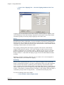
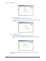
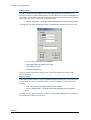
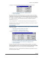
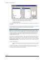
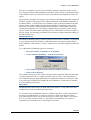
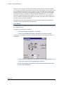
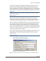
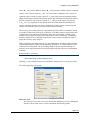
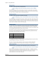
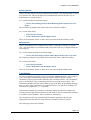
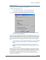
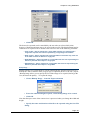
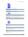
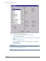
A dialog box will appear with radio buttons indicating the types of members.
Ø
Ø
Click on the radio button corresponding to the type of member you
require
Click on the OK button
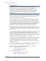
Member Offsets
When modelling a structure there are situations in which members do not extend directly
between two joints but are instead offset from the joints. In other situations, the
intersection between two members may be relatively large and can be considered as a
rigid link. In all these instances, the geometry of the model can be specified to more
accurately model the structure by using rigid connections between the joints and the
members. In Multiframe, these rigid connections are applied using Member Offsets.
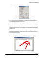
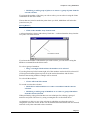
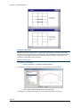
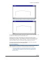
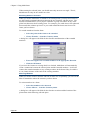
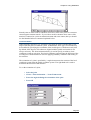
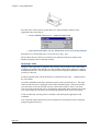
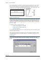
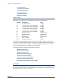
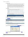
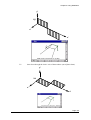
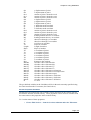
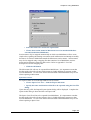
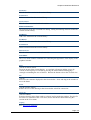
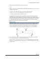
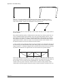
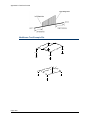
Member Offsets are rigid links between a joint and the end of a member. They are
infinitely stiff and do not deform in bending, shear or axially. Loading on members with
rigid offsets is applied to the flexible portion of the member only (see Member Length on
the diagram below) and distances used to specify the position of loads are measured from
the ends of the rigid offsets.
x1
y1
Member Length
x2
z1
y2
z2
Member Offsets
When Member Offsets are specified, Multiframe considers the length of the member to
be the length of the flexible portion of the member. (Member Length in the diagram
above)
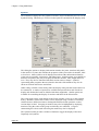
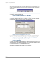
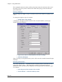
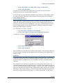
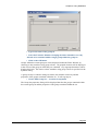
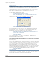
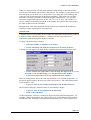
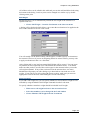
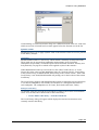
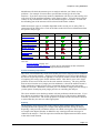
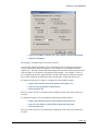
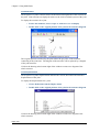
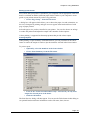
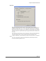
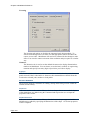
To set the Member Offsets on a member
Page 86
Ø
Select the member or members to be modified
Ø
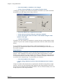
Choose Member Offsets from the Frame menu