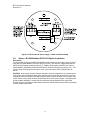
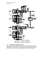
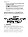
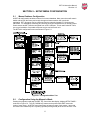
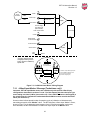
1
BFT-48 User Manual Revision 3.5 INSTRUCTION MANUAL BUCKEYE DETECTION SYSTEMS MODEL BFT-48 TRANSMITTER Warning: Read & understand contents of this manual prior to operation. Failure to do so could result in serious injury or death. Users are responsible for correct translations of this manual into their native language BFT-48 Instruction Manual Revision 3.5 SECTION 1 – SAFETY INFORMATION ......................................................................................... 1 1.1 Safety Information – Read Before Installation & Applying Power ......................... 1 SECTION 2 – INSTALLATION INSTRUCTIONS ........................................................................... 2 2.1 Introduction .................................................................................................................. 2 2.2 Ratings and Certifications .......................................................................................... 3 2.2.1 BFT-48 ATEX Certified Model ............................................................................. 3 2.3 Sensor Location .......................................................................................................... 3 2.4 Mounting the Enclosure.............................................................................................. 4 2.5 System Design Specifications ................................................................................... 5 2.6 Field Wiring Installation .............................................................................................. 6 2.7 2-Wire 4-20mA Intrinsically Safe & Explosion Proof Installations ......................... 6 2.8 3-Wire 4-20mA Mode Installation ............................................................................... 7 2.9 Alarms / RS-485 Modbus BF10-0234 Option Installation ........................................ 8 2.10 Isolated 4-20mA Output 10-0250 Option ................................................................. 10 2.11 Sensor Installation (with Smart / Simple Sensor Definition)................................. 10 2.12 “Sensor Type” and BFT-48 Signal Conditioning ................................................... 11 SECTION 3 – INITIAL START-UP ................................................................................................ 12 3.1 “Transmitter Configuration” Menu .......................................................................... 12 3.1.1 Single / Dual Gas Monitor Configuration ......................................................... 13 3.1.2 Output Zero / Output Span Trims (Factory Preset, Technicians only!): ....... 13 3.1.3 Model Name ............................................................................................................ 13 3.1.4 Real Time Clock ........................................................................................................... 13 3.1.5 Backlight ....................................................................................................................... 13 3.2 Initial Bridge Sensor Monitor Start-Up .................................................................... 14 3.2.1 Initial Bridge Sensor Monitor “Sensor Volts” Check ..................................... 14 3.2.2 Initial Bridge Sensor Monitor “Balance” Check.............................................. 14 3.2.3 Initial Bridge Sensor Monitor “Span” Check ................................................... 14 3.3 Initial Toxic / Oxygen Sensor Monitor Start-Up ...................................................... 14 3.3.1 Initial Toxic / Oxygen Sensor Monitor “Span” Check .................................... 14 SECTION 4 – OPERATING INSTRUCTIONS .............................................................................. 15 4.1 Routine Sensor Calibrations .................................................................................... 15 4.2 ALARM OPERATION ................................................................................................. 16 4.2.1 ALARM 3 – UNDERSTANDING FAULT / LEVEL OPERATION ....................... 16 SECTION 5 – SETUP MENU CONFIGURATION ........................................................................ 17 5.1 Menus Database Configuration ............................................................................... 17 5.2 Configuration Using the Magnetic Wand: ............................................................... 17 5.3 System Configuration Menus: ................................................................................. 18 Measurement Name........................................................................................................ 18 Eunits ............................................................................................................................... 18 Zero .................................................................................................................................. 18 Span ................................................................................................................................. 18 Decimal Points ................................................................................................................ 18 Cal Span Value ................................................................................................................ 18 Readout Deadband ......................................................................................................... 18 Track Negative ................................................................................................................ 19 Temp Compensation ...................................................................................................... 19 Backup Config. ............................................................................................................... 19 Restore Config. ............................................................................................................... 19 Upload Sensor Data ....................................................................................................... 19 Cal Marker ....................................................................................................................... 19 TX Sensor Life ................................................................................................................ 20 5.4 Alarm Settings: .......................................................................................................... 20 5.4.1 Relay Configuration (if equipped): ................................................................... 21 5.5 Sensor Information: .................................................................................................. 21 BFT-48 Instruction Manual Revision 3.5 5.6 CLOCK/DELAY SETUP: ............................................................................................ 22 5.7 LCD Contrast Adj: ..................................................................................................... 23 5.8 HELP Screen: ............................................................................................................. 23 5.9 Diagnostics: ............................................................................................................... 23 5.10 RS-485 / MODBUS SETUP: ....................................................................................... 23 5.10.1 MODBUS REGISTER AND FUNCTION CODE SUMMARY ............................ 24 5.11 SYSTEM SECURITY: ................................................................................................. 27 SECTION 6 – TECHNICIANS ONLY MENUS .............................................................................. 27 6.1 Introduction: .............................................................................................................. 27 6.2 Set Balance / Set Sensor Voltage (Technicians only!): ......................................... 28 6.3 Set Gain to Unity (Technicians only!): .................................................................... 29 6.4 PreAmp Gain Adjust (Technicians only!): .............................................................. 29 6.5 Simple Sensor Input Type (Technicians only!): ..................................................... 29 6.6 Zero Cal Value (Technicians only!): ........................................................................ 30 6.7 Raw Min / Max Counts (Technicians only!): ........................................................... 30 6.8 4-20mA Input Marker / Message (Technicians only!): ........................................... 31 SECTION 7 – SPECIAL ORDER CONFIGURATIONS ................................................................ 31 7.1 ARCTIC Option .......................................................................................................... 31 7.1.1 ARCTIC Smart Sensor Temperature Setpoint Option .................................... 31 7.2 Special Order; 18VAC Primary Power Supply Option ........................................... 31 7.3 Special Order; 4-20mA Input to Bridge Channel .................................................... 32 7.3.1 4-20mA Input Marker / Message (Technicians only!): .................................... 33 BFT-48 User Manual Revision 3.5 SECTION 1 – SAFETY INFORMATION 1.1 Safety Information – Read Before Installation & Applying Power IMPORTANT Users should have a detailed understanding of BFT-48 operating and maintenance instructions. Use the BFT-48 only as specified in this manual or detection of gases and the resulting protection provided may be impaired. Read the following WARNINGS prior to use. WARNINGS Calibrate with known target gas at start-up and check on a regular schedule, at least every 90 days. More frequent inspections are encouraged to spot problems such as dirt, oil, paint, grease or other foreign materials on the sensor head. Do not paint the sensor assembly or the Transmitter. Do not use the BFT-48 if its enclosure is damaged or cracked or has missing components. Make sure the cover, internal PCB’s and field wiring are securely in place before operation. Use only a sensor assembly compatible with the BFT-48 and approved by Buckeye Detection Systems (See the section ____ for Replacement Parts.) *Not Available this printing* Periodically test for correct operation of the system’s alarm events by exposing the monitor to a targeted gas concentration above the High Alarm setpoint. Do not expose the BFT-48 to electrical shock or continuous severe mechanical shock. Protect the BFT-48 from dripping liquids and high power sprays. Use only for applications described within this manual. CAUTION: FOR SAFETY REASONS THIS EQUIPMENT MUST BE OPERATED AND SERVICED BY QUALIFIED PERSONNEL ONLY. READ AND UNDERSTAND INSTRUCTION MANUAL COMPLETELY BEFORE OPERATING OR SERVICING. ATTENTION: POUR DES RAISONS DE SÉCURITÉ, CET ÉQUIPEMENT DOIT ÊTRE UTILISÉ, ENTRETENU ET RÉPARÉ UNIQUEMENT PAR UN PERSONNEL QUALIFIÉ. ÉTUDIER LE MANUE D’INSTRUCTIONS EN ENTIER AVANT D’UTILISER, D’ENTRETENIR OU DE RÉPARER L’ÉQUIPEMENT. 1.2 Contacting Buckeye Detection Systems Buckeye Detection Systems 110 Kings Road Kings Mountain, NC 28086 1-800-438-1028 [email protected] 1 BFT-48 Instruction Manual Revision 3.5 SECTION 2 – INSTALLATION INSTRUCTIONS 2.1 Introduction Important: This manual describes both the 2-Wire and the 3-Wire 4-20mA versions of the BFT48. 2-Wire versions are only possible if the BF10-0232 Display PCB IS THE ONLY PCB IN THE ENCLOSURE. If the BF10-0233 I/O Power Supply is installed it is a 3-Wire version. The BFT-48 is a single or dual channel fixed-point monitor designed to provide continuous monitoring of hazardous gases in the workplace. Monitored values are displayed in their engineering units as well as graphically as a bar graphs or 30-minute trends (Figure 2.1). Input types include Electrochemical toxic / oxygen sensors, catalytic bead combustible sensors, MOS solid-state sensors, as well as various millivolts, volt and 4-20mA inputs. Sensors supplied by the factory include an 8-wire Smart Sensor interface capable of configuration data uploads to the BFT-48. Traditional 3-wire Simple sensors, without the smart interface, are also supported by the BFT-48. Its advanced microcontroller electronics and superior graphic LCD operator interface offers enhanced diagnostics and fault analysis not possible in competing products. The BFT-48 provides a standard 4-20 mA output signal for connection to control systems or other alarm instrumentation. Available options include an Alarm Relay / RS-485-Modbus board or an Isolated 4-20mA output. Non-volatile memory retains all configuration data during power interruptions. The magnetic, non-intrusive calibration can be easily performed by one person without opening the enclosure. A standard “real time clock & calendar” feature allows data logging of calibrations and alarm events for recall to the LCD readout or over the serial port. A separate PC compatible USB Interface allows a Smart sensor to be loaded with configuration variables via a PC and upload this data to the BFT-48. This includes alarm set points, range, target gas, calibration constants and other variables required to match the BFT-48 to a specific application. For traditional Simple sensors, without the smart interface, the USB interface allows direct BFT-48 configuration from a PC or a six channel BFT-48 Educator device. Toxic and oxygen monitors are capable of 2-wire 4-20mA operation (section 2.7) when the alarms / Modbus option and LCD backlight are not required. Catalytic LEL sensors, or addition of the 100234 Alarms / Modbus option, require the BF10-0233 I/O Power Supply board providing 3-wire 420mA operation (section 2.8). Only periodic calibration checks are needed to assure dependable performance. Operator interface is very intuitive with the LCD displaying data both graphically as bar-graphs / trends and in engineering units (Figure 2-1). Additional features include: No potentiometer or jumper settings required. All setup is with menus accessed via the LCD / magnetic keypad operator interface without opening the enclosure. Field adjustable alarm levels may be high, low, fault, fail-safe, latching and acknowledgeable. New alarms cause front LED’s to flash and become steady after acknowledge. CAL MODE advises when to apply gas during calibrations One half hour trend screen shows rate of change of gas exposures Sensor life bar-graph updates after each SPAN calibration. Modular design affords efficient installation and plug in sensors allow changing target gases after installation New smart sensors are recognized by the BFT-48 and prompts users to either upload new configuration data or continue with data from the previous smart sensor. Sensors are industry proven for fast response and long life. 2 BFT-48 Instruction Manual Revision 3.5 Engrg. Units / Bar Graph ALM RST UP/ ALM1 ALM2 ALM RST UP/ ALM1 ALM2 NEXT FAIL 10 10 % L EL Me a s u r e me n t DOWN/CAL N a me Dual Channel Split Screen (Dual Sensor Mode Only) Engrg. Units / 30-Minute Trend RXD % FAIL ALM RST UP/ ALM1 ALM2 NEXT L EL NEXT key toggles readout RXD RS485 RS485 TXD TXD EDIT DOWN/CAL EDIT NEXT key toggles readout NEXT FAIL 17 . 8 % O2 D e f . DOWN/CAL RXD RS485 0 % A1 A2 L EL TXD EDIT Figure 2-1: Data Displays 2.2 Ratings and Certifications CSA certified for Division 1 & 2 hazardous area installations for explosion proof Class 1 Groups B,C,D, and intrinsically safe (BFT-48/EC 2-wire loops only) Class 1 Groups A,B,C,D. Also see sections 2.7, 2.7a & 2.8. Designed to meet CSA C22.2 No.152 for Combustibles Monitors and ISA 92.0.01 Part 1 for Toxic Monitors. 2.2.1 BFT-48 ATEX Certified Model An ATEX certified BFT-48 model (certificate # DNV-2007-OSL-ATEX-1845) is also available by changing the BFT-48 designation to BFT-ATEX48. ATEX certified models including sensors are supplied only with sensor head part # BF10-2072 and are not available with the BF10-0247 sensor head or the BF0010-1200 “Y” fitting. ATEX installations must be in compliance with EN60079-14 or suitable National or international standard and all cable glands and closing devices must carry a suitable ATEX marking. The ATEX label is shown below: 2.3 Sensor Location Factors such as air movement, gas density in relation to air, emission sources and environmental variables affect correct sensor location. Air movement by fans, prevailing winds and convection should be carefully evaluated to determine if a leak is more likely to raise gas levels in certain areas within the facility. Vapor density of a gas determines if it will rise or fall in air when there are no significant currents. Lighter than air gases should have the monitors mounted 12 – 18 inches (30 – 45 centimeters) above the potential gas leak and heavier than air gases should be this distance below. Even though the BFT-48 is designed for rugged service, sensors should be protected from environmental damage from water, snow, shock, vibration and dirt. 3 BFT-48 Instruction Manual Revision 3.5 2.4 Mounting the Enclosure The BFT-48 standard enclosure is a cast aluminum explosion-proof (NEMA 7) enclosure as shown in Figure 2-2. Figure 2-2a shows dimensions with the dual local sensor ‘Y’ included. Figure 2-2: BFT-48 Explosion-Proof Housing 0010-1200 “Y” Fitting not available on ATEX compliant model Figure 2-2a: BFT-48 Explosion-Proof Housing with Dual Sensor Head Adaptor Modular design simplifies the installation of the BFT-48 (Figure 2-3). A top Display Assembly is mounted with captive thumbscrews and is easily removed to access field-wiring terminals. An optional BF10-0234 Alarms/Modbus board mounts piggyback to the back of the Display Assembly. Wiring from toxic or oxygen sensors terminates at the BF10-0232 Display Assembly along with 2-wire 4-20mA signal wires. This Display Assembly is the only PC board supplied with toxic / oxygen BFT-48s not requiring relays, RS-485 Modbus or LCD backlight. The optional bottom BF10-0233 I/O Power Supply board generates voltages needed for LCD backlight, relays, 4 BFT-48 Instruction Manual Revision 3.5 RS-485 Modbus and Bridge sensor and is required with any of these I/O functions. The enclosure is equipped with two threaded 3/4 inch NPT conduit fitting outlet and pre-drilled mounting flanges. WARNING: Qualified personnel should perform the installation according to applicable electrical codes, regulations and safety standards. Insure correct cabling and sealing fitting practices are implemented. Do not aim the sensor pointing upward. Install the BFT-48 to a wall or bracket using the predrilled mounting flanges with I.D. 0.25 on 5.5 inch centers (Figure 2-2). If conduit is rigid and able to support the weight of the BFT-48, the mounting bolts may be omitted. CAUTION: The sensor should never be installed pointing upwards. ATEX compliant model requires 10-2072 ATEX marked sensor head Figure 2-3: Outline Drawing 2.5 System Design Specifications Supply Voltage: 10 to 30 volts Power Consumption: With a typical .5 watt Bridge Sensors (requires BF10-0233 I/O Power Supply and 3-wire operation): 100 mA @ nominal 24 VDC Toxic/Oxygen Sensors without Relays / Modbus Option (2-wire 4-20mA operation): 25 mA max @ nominal 24 VDC. Relays / RS-485 Modbus Option Board (requires BF10-0233 I/O Power Supply and 3-wire operation): 40 mA per relay (120 mA total with all 3 energized); RS-485 use adds 20mA Memory: Non-volatile E2 memory retains configuration values in the event of power outages. 5 BFT-48 Instruction Manual Revision 3.5 Loop Resistance at nominal 24 VDC power: 650 ohms maximum in 2-wire mode 750 ohms maximum in 3-wire mode. Relays (Optional): Three configurable form C (SPDT) relays rated for 5 amp at 30 VDC or 240 ~VAC RESISTIVE. Relay 1 and Relay 2 level alarms are configurable for HIGH or LOW trip, for normally energized (Failsafe) or normally de-energized and for latching or non-latching. Relay 3 is always normally energized for failsafe operation so loss of power to the BFT-48 will be indicated as a “FAULT” condition. CAUTION: Relays are rated for RESISTIVE loads. Inductive loads, such contactor coils or motors may cause contact arcing, which emits RFI into the sensor signals. Use appropriate snubbers and MOV’s across inductive loads and keep wiring away from signal wires. 2.6 Field Wiring Installation 4-20mA Transmission Range Info: The distance 4-20 mA signals can travel is dependent upon several factors including the cable gauge, DC power supply voltage level and impedance of the input of the receiving device. Assuming a nominal 24 VDC power supply, maximum total loop resistance is 650 ohms in the 2wire mode. Note: BFC-16 Controllers have 4-20mA input resistance of 100 ohms. 2.7 2-Wire 4-20mA Intrinsically Safe & Explosion Proof Installations BFT-48/EC’s equipped with BF10-0247 sensor heads are NRTL (Nationally Recognized Testing Lab) certified as suitable for both intrinsically safe and explosion proof installations. BFT-48/EC’s equipped with BF10-0247IS sensor heads (XP flame arrestor is not installed to allow monitoring of highly reactive gases such as chlorine) are NRTL certified as suitable for intrinsically safe installations. All BFT-48/EC’s are NRTL certified for explosion proof installations as long as the sensor head is CSA certified as explosion proof. Contact Buckeye Detection Systems for Installation Drawing # BF11-0100 for correct intrinsically safe installations. Description: The 2-wire current sinking transmitter is the easiest and most economical to install since there are only two wires. All of the power needed comes from the current loop and wire sizes may be smaller. However, only very low power applications are eligible for such transmitters. The BFT48/EC Display assembly shown in Figure 2-4 consumes <2.5 mA of quiescent current. Toxic and oxygen electrochemical sensors generate their own signals and therefore require no additional current. If a 4-20mA output is all that is required for toxic / oxygen measurements (no LCD backlight, alarms or RS-485) the BFT-48/EC may be used in the 2-wire mode. CAUTION: It is important to understand the receiver, or controller device must supply the loop power in 2-wire 4-20mA modes. Be sure the receiver to be used supports this type of operation. Instructions: Unscrew the cover on the BFT-48/EC explosion-proof enclosure. Loosen the 2 thumbscrews holding the display assembly in place and remove it. A small sensor cable is attached with sufficient length to allow access to the back of the display assembly where 2 position TB1 is located. Route the receiver wires through the conduit entry and connect to TB1. Steering diodes in the BFT-48/EC 2-wire 4-20mA output automatically correct for polarity so positive and negative are interchangeable. Reassemble the BFT-48/EC. Follow the procedures and recommendations in the receiver manual to complete the installation. Be sure the BFT-48/EC enclosure and conduit are properly grounded. Apply loop power by appropriately powering the receiver device (DCS, PLC, Controller, etc) and the BFT-48/EC should function. Proceed to section-3. 6 BFT-48 Instruction Manual Revision 3.5 Figure 2-4: BF10-0232 Display / 2-Wire 4-20mA Assembly 2.8 3-Wire 4-20mA Mode Installation CAUTION: BFT-48’s equipped with the BF10-0233 I/O Power Supply board only operate as 3 or 4-wire 4-20mA transmitters and are not compatible with 2-wire intrinsically safe installations (see sections 2.7 and 2.7a). Such units should not be combined with BF10-0247IS Sensor Heads without flame arrestors unless the area is classified as non-hazardous. BFT-48’s equipped with the BF10-0233 I/O Power Supply and BF10-0234 Alarms / Modbus option are NRTL certified as suitable for Div 1 & 2 Groups B,C,D explosion proof installations with the BF10-0247 or with any sensor head with an equivalent CSA certification. Description: 3-wire sourcing transmitters require an additional dedicated 24 VDC wire. The 4-20mA loop current is then delivered, or sourced, from the transmitter output and the receiver device must not provide 24 VDC from its input terminal. When the BFT-48 is equipped with the bottom BF100233 I/O Power Supply board shown in Figure 2-5, the 2-wire 4-20mA output is disabled and one of the BF10-0233’s 3-wire outputs must be used. TB2 terminal 2 is for ECHEM toxic / oxygen 3wire 4-20mA output signals and TB2 terminal 3 is for LEL 3-wire 4-20mA output signals. Instructions: Unscrew the cover on the BFT-48 explosion-proof enclosure. Loosen the 2 thumbscrews holding the display assembly in place and remove it. A small ribbon cable is attached with sufficient length to allow access to the I/O PCB mounted in the bottom of the enclosure (Figure 2-5). Power and signal connections are to TB2 where 24 VDC, Signal and Common wires must be connected. A blocking diode protects the BFT-48 if polarity of the power supply is reversed but it will not operate. Reassemble the BFT-48. Follow the procedures and recommendations in the receiver and power supply manuals to complete the installation. Be sure the BFT-48 enclosure and conduit are properly grounded. Apply power and the BFT-48 should function. Proceed to section-3. 7 BFT-48 Instruction Manual Revision 3.5 Figure 2-5: BF10-0233 I/O Power Supply / 3-Wire 4-20mA Assembly 2.9 Alarms / RS-485 Modbus BF10-0234 Option Installation Description: The optional BF10-0234 Alarms/RS-485 Modbus board supplies two level alarm relays, a FAULT relay and an RS-485 Modbus RTU slave port (Figure 2-6). This board is “piggybacked” behind the BF10-0232 Display Assembly (Figure 2-3). Addition of this option requires 3-wire mode 420mA operation and thereby requires the BF10-0233 I/O Power Supply board (Figure 2-5). This is since relays and RS-485 circuits require much more power than 2-wire 4-20mA loops can deliver. CAUTION: Alarm relays have dry contacts and power must be supplied from an external source. If this power source exceeds 3 amps users should consider fusing relay wiring with 3 amp fuses. Contacts are rated for RESISTIVE loads! Inductive loads, such as contactor coils or motors, may cause contact arcing, which shortens life and emits RFI into the sensor signals. Use appropriate arcing snubbers and MOV’s across inductive loads and keep wiring away from signal wires. External wiring to TB3 (Remote Alarm Reset) should be shielded and protected from noise spikes to prevent false Alarm Reset. 8 BFT-48 Instruction Manual Revision 3.5 Remote Alarm Reset TB3 P1 Assy: 10-0234 ST-48 Alarm / ModBus Option NO 1 Relay 1 (K1) C K1 2 NC 3 NO 4 Relay 2 (K2) C K2 5 NC 6 C 8 A 2 B 3 S 4 A 5 B U1 J1 A (Installs RS-485 Terminating Resistor) B (Omits RS-485 Terminating Resistor) TB2 RS-485 ‘A’ & ‘B’ terminals are connected internally for easier IN / OUT cabling. ‘S’ is “no connect” for shield to continue. NO 7 Relay 3 (K3) 1 K3 NC 9 TB1 Figure 2-6: BF10-0234 Alarm Relays / Modbus Option Instructions: Unscrew the cover on the BFT-48 explosion-proof enclosure. Loosen the two thumbscrews holding the display assembly in place and remove it. A small ribbon cable is attached with sufficient length to access the back of the Display assembly where the Alarms/RS-485 Modbus board option is located. It is possible to use only the relays, only RS-485, or use both. Relay terminals are labeled NO (normally open), NC (normally closed) and C (common or the pole). These designators correspond to the shelf, or de-energized, state of the relays. The FAULT relay is always failsafe, meaning it is energized when there is not a fault condition and therefore its action is reverse of the designators. RS-485 Modbus networks should be wired as shown in Figure 2-7. Each BFT-48 connected represents an RTU and must have a unique RTU address. RTU addresses are assigned in the Modbus setup menu described in section 4.10. Cabling must be a “daisy chain” as opposed to a “star” pattern for reliable operation. The “end of line” unit should have J1 installed in the ‘A’ position for terminating resistor installation. All others should have J1 in the ‘B’ position. Front panel Rx / Tx LEDs are helpful troubleshooting tools. Figure 2-7: RS-485 Modbus Wiring 9 BFT-48 Instruction Manual Revision 3.5 2.10 Isolated 4-20mA Output 10-0250 Option Description: The optional BF10-0250 Isolated 4-20mA option (Figure 2-8) provides dual 4-20mA outputs that are electrically isolated from sensor inputs and the 24 VDC power source. Each 4-20mA output share the same common terminal and are not isolated from each other. This board is “piggybacked” behind the BF10-0232 Display Assembly (Figure 2-3). Addition of this option requires 4-wire mode 4-20mA operation and thereby requires the I/O Power Supply board (Figure 2-5). P1 1/2A Isolated 4-20mA Output Option Assy: 10-0250 FUSE U8 1 - TB1 2 3 + 4 + - Figure 2-8: BF10-0250 Isolated 4-20mA Output Option 2.11 Sensor Installation (with Smart / Simple Sensor Definition) Many manufacturers offer industry standard electrochemical and catalytic bead sensors for toxic / oxygen and LEL combustible gas detection. These are referred to as Simple sensors in this manual. The BFT-48 design accommodates users wishing to continue use of their existing simple sensors by accepting electrochemical types into TB2 of the BF10-0232 Display Assembly or catalytic bead types into TB1 of the BF10-0233 I/O Power Supply (mounted to the bottom of the enclosure). The BFT-48 Smart Sensor interface also uses proven electrochemical technology for toxic / oxygen and catalytic bead for LEL combustibles BUT has taken this technology a step further. A tiny memory IC is incorporated into BFT-48 factory supplied Smart sensors allowing them to contain the entire database of BFT-48 parameters onboard the replaceable Smart Sensor assembly (Figure 2-9). This unique Smart Sensor Interface may be used to configure smart sensors and / or BFT-48’s from a PC rather than entering all variables via the magnetic keypad. Electrochemical and catalytic bead smart sensors both plug into the BF10-0247 Smart Sensor Head that connects to BFT-48 electronics with its 8-conductor Smart Sensor Interface cable (Figure 2-9). CAUTION: BF10-0247 Smart sensor heads with electrochemical toxic / oxygen sensors must connect to S1 located on the back of the BF10-0232 Display Assembly (Figure 2-4). BF10-0247 Smart sensor heads with catalytic bead combustible sensors must connect to S1 located on the optional I/O PCB assembly (Figure 2-5). 10 BFT-48 Instruction Manual Revision 3.5 Figure 2-9: BF10-0247 Smart Sensor Head Assembly Smart Sensors are automatically recognized by the BFT-48. The Smart Sensor identification screen in Figure 2-10 is shown after power-up, upon installation of a new smart sensor or by viewing INPUT type in the SENSOR SETTINGS / INFO menu (section 5-5). S MA R T Ty pe: Sp a n : Zer o: S N: B o r n On : Last Ca l : A NY k e y S E N S OR Ca t - B e a d 10 0 0 xxxxxx 0 1/ 2 8 / 0 4 04/ 05/ 04 t o Ex i t E R R OR C OD E 01 Incor r ect Se n s o r i nst al l ed. Inst al l cor r ec t s ensor or u p d a t e t r a n s mi t t e r . S E E MA N U A L E DI T k e y t o u p d a t e . An y o t h e r t o abor t . If installed sensor type does not match transmitter database Figure 2-10: Smart Sensor Info / ERROR Screens 2.12 “Sensor Type” and BFT-48 Signal Conditioning Catalytic bead and electrochemical sensors obviously have different signal conditioning requirements. In addition, same sensor types have different response coefficients, signal strength and gain and offset requirements. The block / wiring diagram in Figure 2-11 illustrates how BFT-48’s are able to accept many sensor types without the need of manual potentiometers or jumpers. Smart Sensors carry this setup information with each sensor. 11 BFT-48 Instruction Manual Revision 3.5 Figure 2-11: BFT-48 Block / Wiring Diagram SECTION 3 – INITIAL START-UP 3.1 “Transmitter Configuration” Menu Figure 3-1shows the BFT-48 XMITTER CONFIG menu used to activate channels, precisely calibrate 4-20mA outputs and set time / date. Its menus are set at the factory and typically not needed by the user. To access from any data display, press and hold the NEXT key for 5seconds until the screen appears requesting a special key sequence (4-UP keystrokes). 12 BFT-48 Instruction Manual Revision 3.5 X MI T T E R HOLD NEXT KEY 5-SECONDS En t e r Ke y Se q u e n c e t o a c c e s s me n u . * * * * NE X T k e y t o E x i t . Se e Ma n u a l / PRESS UP KEY 4-TIMES HE L P O2 / L EL Ou t Ou t Re a Mo d Ba c C ON F I G T OX I C / CURRE NT put Zer o put Sp a n l T i me C l o c k e l ST- 4 8 kLi ght ON ON > > > ON Figure 3-1: Transmitter Configuration Menu 3.1.1 Single / Dual Gas Monitor Configuration BFT-48EC’s are 2-wire 4-20mA devices and support only one electrochemical sensor. Addition of the BF10-0233 Power Supply board (BFT-48LEL) automatically adds the catalytic bead sensor input and dual 4-20mA outputs. If both the O2/TOXIC and LEL/Current menu items are ON, the BFT-48 will function as a dual gas monitor with both sensor inputs and 4-20mA outputs active. Either input may be turned off for single gas EC or LEL monitors. 3.1.2 Output Zero / Output Span Trims (Factory Preset, Technicians only!): The Output Zero Trim / Output Span Trim entries are digital to analog (D2A) values that determine the BFT-48’s final 4-20mA output. Their purpose is to provide precise BFT-48 4mA and 20mA outputs. To trim these values, attach a precision milliamp meter to the BFT-48 420mA output being used. Enter the correct OUTPUT ZERO TRIM menu shown in Figure 3-2. Use the UP/DOWN keys to trim the milliamp value to 4.00mA. Next, enter the correct OUTPUT SPAN TRIM menu and use the UP/DOWN keys to trim the milliamp value to 20.00mA. Press the NEXT key to exit this menu. The BFT-48 stores these new D2A values and uses them as the 0 & 100% of full-scale endpoints. WARNING: Target gas monitoring and alarm processing are halted during these adjustments. Figure 3-2: Output ZERO / SPAN Trim Menus 3.1.3 Model Name When power is applied to the BFT-48 it will briefly show a 10 digit ASCII model name or company name as it starts up. The name can be edited in the Transmitter Configuration menu by editing the Model field. 3.1.4 Real Time Clock Adjust the date and time here for use in EVENT LOGGING. This is a factory setting but may need to be adjusted for the end users location. 3.1.5 Backlight During high power mode this menu allows the user to turn the backlight off. There are three settings ON, OFF and TIMED. During TIMED mode the backlight will turn on when a key is hit, during calibration process and when an alarm is present. It will stay on for 15 seconds after any of these events clear. 13 BFT-48 Instruction Manual Revision 3.5 3.2 Initial Bridge Sensor Monitor Start-Up BFT-48 LEL Monitors that are factory equipped with a local Simple or Smart Bridge sensor rarely require adjustments, other than routine calibrations, to provide accurate LEL readings. However, after installation the following checks should be performed to insure proper operation. In addition, alarm levels, Measurement Name ASCII fields and other variables may require configuration by users in order to best serve their application. 3.2.1 Initial Bridge Sensor Monitor “Sensor Volts” Check CAUTION: Sensor Volts in excess of the rated values may destroy catalytic bead sensors. BFT-48 sensors are rated for 2 volts. Section 6.2 describes reading and setting “sensor volts” using the BFT-48 LCD. The voltage displayed on the LCD is monitored across TB1-REF and TB1-ACT on the BFT-48 Power Supply board (Figure 2.4) and may be confirmed with a voltmeter. This TB-1 value is correct for locally mounted sensors only. Sensors mounted more than a few feet away from the BFT-48 may receive a lower voltage due to the inherent voltage drop across sensor wiring. Remote mounted sensors must have their sensor voltage (across ACTIVE and REFERENCE beads) measured AT THE SENSOR end of the cable. The BFT-48 setting will require a higher value in order to achieve the correct voltage at the sensor. Correct sensor voltage should be confirmed after startup for locally and remotely mounted catalytic bead sensors. 3.2.2 Initial Bridge Sensor Monitor “Balance” Check Catalytic bead sensors connect to a bridge circuit that may require a balance adjustment after installation especially when the sensor is remote mounted from the BFT-48. Section 6.2 describes using the LCD to read and adjust BALANCE settings. Correct BALANCE setting should be confirmed after start-up for locally and remotely mounted catalytic bead sensors. 3.2.3 Initial Bridge Sensor Monitor “Span” Check Prior to the initial Routine Sensor Calibration described in section 4.1, a coarse SPAN gas reading verification should be performed after installation. After correct Sensor Volts and BALANCE have been verified, apply an upscale gas value such as 50% LEL to the sensor. The indicated value should read between 35 and 65% LEL with 50% LEL gas applied. Larger errors may indicate incorrect sensor wiring or defective sensor. Remember that this is only a coarse check and precision calibrations are performed in Routine Sensor Calibrations described in the following section 4.1. Section 6.4 describes PREAMP GAIN adjustments that may be required if full-scale ranges are changed. 3.3 Initial Toxic / Oxygen Sensor Monitor Start-Up BFT-48 Toxic / Oxygen Monitors, factory equipped with a local Simple or Smart electrochemical sensor, rarely require adjustments (other than routine calibrations) to provide accurate readings. However, after installation the following checks should be performed to insure proper operation. In addition, alarm levels, Measurement Name ASCII fields and other variables may require attention by users in order to best serve their application. 3.3.1 Initial Toxic / Oxygen Sensor Monitor “Span” Check Prior to the initial Routine Sensor Calibration described in section 4.1, a coarse SPAN gas reading verification should be performed after installation. Apply an upscale gas value of at least 25% of full scale to the sensor. For example, if 0-100ppm H2S is the measurement range, apply at least 25ppm but not more than 100ppm. The indicated value should read within 15% of full scale. Remember that this is only a coarse check and precision calibrations are performed in Routine Sensor Calibrations described in the following section 4.1. Section 6.4 describes PREAMP GAIN adjustments that may be required if full-scale ranges are changed. 14 BFT-48 Instruction Manual Revision 3.5 SECTION 4 – OPERATING INSTRUCTIONS 4.1 Routine Sensor Calibrations Calibration is the most important function for insuring correct operation of the BFT-48. The CAL MODE (flow chart shown in Figure 4-2) is designed to make calibration quick, easy and error free. A successful ZERO and SPAN calibration requires only four keystrokes. The 4-20mA output indicates CAL MODE by transmitting 3mA for 2-wire installations and 1.5mA for 3-wire installations. It then transmits 4mA during the subsequent CAL PURGE delay to prevent external alarms during calibration. Local BFT-48 alarm relays (if equipped) are inhibited during CAL MODE. CAL MODE automatically exits if no keystrokes are detected after 5 minutes. Follow these BFT-48 calibration guidelines: Calibration accuracy is only as good as the calibration gas accuracy. Buckeye Detection Systems recommends calibration gases with NIST (National Institute of Standards and Technology) traceable accuracy to increase the validity of the calibration. Do not use a gas cylinder beyond its expiration date. Calibrate a new sensor before use. Allow the sensor to stabilize before starting calibration (approximately 5 minutes). Calibrate on a regular schedule. (Buckeye Detection Systems) recommends once every 3 months, depending on use and sensor exposure to poisons and contaminants.) Calibrate only in a clean atmosphere, which is free of background gas. Figure 4-1: Calibration Gas Input Use the following step-by-step procedure to perform ZERO and SPAN calibrations. 1. To enter the CAL MODE from either data display, press the DOWN / CAL key and within 5 seconds press the EDIT key. 15 BFT-48 Instruction Manual Revision 3.5 2. Using the Cal-Cup, apply a clean ZERO gas or be sure there is no background target gas in the monitored area. After the reading is stable, (approximately 1 minute) press the EDIT key to perform a ZERO calibration. 3. If the ZERO calibration is successful, press the NEXT key to proceed to the SPAN check. 4. Apply the correct SPAN gas at .5 liters/min. After the reading is stable, (approximately 1 minute) press the EDIT key to perform a SPAN calibration. WARNING: The SPAN gas used must match the value specified since this is what the BFT-48 will indicate after a successful SPAN calibration. The Cal Span Value may be edited if it becomes necessary to apply a different gas concentration (see Cal Span Value in section 5.3). 5. If the SPAN calibration is successful, the display flashes “REMOVE CAL GAS” and starts the CAL PURGE delay. 6. CAL MODE will be complete after the end of the CAL PURGE delay. The flow chart in Figure 4-2 illustrates the above procedure. UP, CAL, NEXT & EDIT labels indicate keystrokes using the magnetic wand. The CAL MODE information screen (top of the chart) is available for advanced users to see Offset / Gain calibration constants and live analog to digital converter (A/D) counts. Span Gas calibration values may also be edited from this screen. Holding the UP key, for 5 seconds during CAL MODE, displays this screen. Calibration history records are logged and may be viewed in the Sensor Information menu (see section 5-5). Figure 4-2: Cal-Mode Flow Chart and Menus 4.2 ALARM OPERATION BFT-48’s have front panel LED indicators for Alarm 1, Alarm 2 and Alarm 3. An optional BF100234 Relay/Modbus board adds K1, K2 & K3 relays for these alarms. CAUTION: BFT-48 Alarm LED indicators function even without the presence of the BF10-0234 Relay option. With 2-Wire 4-20mA operation, to conserve power, alarm LED’s only flash during alarm events. With 3-Wire 4-20mA operation, alarm LED’s flash when new, and become steady after an operator ACKNOWLEDGE - pressing the UP/RESET key. 4.2.1 ALARM 3 – UNDERSTANDING FAULT / LEVEL OPERATION The “A3” alarm is typically dedicated to FAULT conditions indicating sensor failures or “out of measurement range” conditions. However, some applications require a third level alarm. The A3 menu is identical to A1 & A2 and may be set to trip at an upscale level value. A3 WILL ALSO TRIP WITH MISSING OR FAILED SENSORS REGARDLESS OF THE LEVEL VALUE! CAUTION: Missing or failed sensors always trip Alarm 3 and relay K3 (if equipped). This is true even with A3 configured as a level alarm and it must be accepted that A3 level alarm events might be caused by the monitored level, or, by a missing or failed sensor. 16 BFT-48 Instruction Manual Revision 3.5 SECTION 5 – SETUP MENU CONFIGURATION 5.1 Menus Database Configuration All BFT-48 configuration variables are stored in its menu database. Many menu items will contain default values from the factory and require changes to better match a user’s particular application. BFT-48 menus may be configured from the magnetic keypad in 5-10 minutes per transmitter. For installations consisting of numerous points, an interface device is offered to allow Smart sensors and BFT-48’s be configured from a PC’s USB port. This is useful when BFT-48’s are not yet installed or if a portable computer may be carried to each unit. The BFT-48’s configuration menus are shown in Figure 5-1. Figure 5-1: Configuration Menu Tree 5.2 Configuration Using the Magnetic Wand: Passing the magnetic wand past the EDIT key, from either data display, displays SETUP PAGE 1 as shown in Figure 5-2. The UP / DOWN keys maneuver the pointer while EDIT enters sublevels of menu items. All SETUP menu items have at least one page of sub-menus. Items with sub-menus are indicated by the > symbol (right hand pointing arrow) at the end of each line. Edit 17 BFT-48 Instruction Manual Revision 3.5 menu items by pointing to them, press the EDIT key to display the cursor, press UP / DOWN to change that character, press NEXT to move the cursor, then press EDIT again to load the new item and remove the cursor. Press NEXT to reverse out of the sub-menu. To view SETUP PAGE 2, press the DOWN key with the pointer aimed at the bottom item on PAGE 1. L E L I NP UT 1 S y s t e m Co n f i g . Al a r m Se t t i n g s Se n s o r I n f o r ma t i o n Cl o c k / De l a y s Di a g n o s t i c s HE L P (Instructions) L EL > > > > > > EDIT L CD Mo d b Se c u Tec h Se n s Fi I NP UT 2 Co n t r a s t Ad j . u s RS 4 8 5 P o r t r i t y n i c i a n s ON L Y or T e mp r mw a r e R e v . > > > > > “Sensor Temp” menu only present with “Arctic” smart sensor installed. See section 7.1. Figure 5-2: Setup Menu Entry 5.3 System Configuration Menus: The System Config. group consists of two pages of menus as shown in Figure 5-3. Each item’s description follows in this section. S Y S T E M C ON F I G. P G 1 Me a s u r e me n t N a me - 16 E u n i t s X X X X X X X X X X - 10 Z e r o ( 0 %) (Eunits) S p a n ( 10 0 % ) (Eunits) D e c i ma l P o i n t s 0 Ca l S p a n Va l 50 UP/ DOWN S Y S T E M C ON F I G. P G 2 Re a d o u t De a d b a n d 0 % T r a c k Ne g a t i v e NO T e mp C o mp e n s a t i o n > B a c k u p Co n f i g . > > *R e s t o r e or **U p l o a d C a l Ma r k e r 3 . 0 0 mA TX Se n s o r L i f e NO *Simple Sensor Installed **Smart Sensor Installed *“Restore” available only without smart sensor installed. **“Upload” available only with smart sensor installed. Figure 5-3: System Config. Menus Measurement Name may be edited to contain virtually any 16-character ASCII field. It is typically used to describe the monitored point by user tag # or other familiar terminology. Eunits (engineering units) may have up to a 10 character ASCII field. Many common gases have pre-configured Eunits based upon the sensor type and each may be edited in this menu as described in Configuration Using the Magnetic Wand section 5-2. Zero (0%) defines the reading to be displayed when 4mA (0%) is the BFT-48 output. Span (100%) defines the reading to be displayed when 20mA (100%) is the BFT-48 output. The highest reading allowed is 9999 includes negative polarity sign and one decimal point. Polarity is only indicated for negative readings. Decimal Points sets the resolution of the LCD readings and may be for 0, 1 or 2. Example: ZERO readings for 0, 1 & 2 DP’s respectively are 0, 0.0 & 0.00. Cal Span Value sets what upscale value must be applied when performing Span calibrations. Readout Deadband allows forcing low values to continue to read zero. This is useful when there are small amounts of background gases that cause fluctuating readouts above zero. The highest amount of deadband allowed is 5%. The 4-20mA output is not affected by this menu item. 18 BFT-48 Instruction Manual Revision 3.5 Track Negative, set to NO, causes negative values to read the Zero (0%) value in data displays. The CAL MODE readout displays negative values regardless of this setting and negative values below the Fault set point will still cause the Fault alarm to trip. The 4-20mA output always locks at 4mA when the reading is negative. Temp Compensation allows user to adjust the gain and offset that is applied to sensors to compensate for temperature drift. Factory supplied sensors are preprogrammed with these values are automatically uploaded to the BFT-48 from the smart sensor. The default values are 1.000 for gain and 0.000 for offset. With these default values entered there is no extra gain or offset applied to the sensor. This menu is not accessible unless a smart sensor that is equipped with the temperature sensor is installed. From the menu pictured in Figure 5-4 enter the gain and offset that will be applied into the BFT-48. The gain is applied to the span value. This number is multiplied to the preamp gain value that is set prior to the initial calibration for each of the specified temperatures (-40°C - 60°C in 10° increments). Offset is the needed adjustment to make the sensor read zero at the different temperatures. To prevent accidental data entry a special keystroke sequence, of 4 consecutive UP keys, is required to enter this menu. C OMP E N S A T I ON En t e r Ke y Se q u e n c e t o a c c e s s me n u . * * * * NE X T k e y t o E x i t . Se e Ma n u a l / PRESS UP KEY 4-TIMES T E MP GA I N % of f s et - 40.0C 1. 0 0 0 0.000 HE L P Figure 5-4: Temperature Compensation Menu Backup Config. allows users to store the entire current BFT-48 menu database into nonvolatile memory for restoration later if incorrect values are accidentally entered or uploaded. Restore Config. restores the BFT-48 menu database to the values from the most recent Backup Config. This menu item is only available if a smart sensor is not installed. The special keystroke sequence of 4 consecutive UP keys is also required to perform backup and restore operations. Upload Sensor Data allows manually uploading the entire smart sensor database to the BFT-48 from the smart sensor. Cal Marker allows setting the 4-20mA output value during ZERO and SPAN calibrations at a level to prevent alarm trips by calibration values. 3-Wire models may be set from 0 to 20mA. Quiescent current of 2-wire models limits this setting to 3 to 20mA. 19 BFT-48 Instruction Manual Revision 3.5 TX Sensor Life set for YES, causes the BFT-48 4-20mA output to transmit a sensor life value after successful calibrations during the CAL PURGE delay (see section 4.1). Normal operation is the BFT-48 transmits 4mA during the CAL PURGE delay. But with TX Sensor Life = YES it transmits 4mA for the first 10-seconds, then for 5-seconds transmits a value between 4mA and 5mA, with 4mA equal to 0% sensor life and 5mA equal to 100% sensor life (see Figure 5-5). The output then returns to 4mA for the remainder of the CAL PURGE delay. For example, if after a calibration sensor life is 75%, the BFT-48 transmits 4.75mA during the 5-second interval. Note: TX Sensor Life should always be set for NO unless the 4-20mA receiver is capable of interpreting the sensor life signal. The Buckeye Fire BFC-16 Controller is capable of this function. Figure 5-5: Transmit Sensor Life Timing Diagram 5.4 Alarm Settings: The Alarm Settings page has the Alarm 1, 2, 3 Setups, Relays and Event Log submenus shown in Figure 5-6. Alarm 1, Alarm 2 and Alarm 3/Fail menus are identical and therefore described only once in this section. IMPORTANT: Alarm functions and their associated LED’s are active without the BF10-0234 Relay / Modbus option installed. Alarm 1, 2, 3 menus are identical A L A RM Al a Al a Al a Re l Al a r r r a r m m m ys m S E T T I N GS 1 2 3/ Fai l Co n f i g . Ev e n t Log A L A RM > > > > > x E V E NT RE L A Y S E T UP Se t Po i n t De a d - B a n d ON D e l a y OF F D e l a y Low Tr i p Lat chi ng L OG C ON F I G K1 Fa i l s a f e NO K2 Fa i l s a f e NO K 2 A c k n o wl e d g e NO K 2 Re f r e s h Of f * K 3 a l wa y s F a i l s a f e * 20 1% 0s 0m NO NO Edit Di s p l a y E v e n t Log Cl e a r Ev e n t Log 0 0 0 0 0 0 0 0 8 8 8 8 8 8 8 8 / / / / / / / / 12 12 12 12 12 12 12 13 / / / / / / / / 0 0 0 0 0 0 0 0 4 4 4 4 4 4 4 4 0 3 : 17 03:51 03:55 0 4 : 16 04:23 15 : 0 0 16 : 4 3 02:08 A1 I N A2 I N A CK A 2 OU T A 1OU T A1 I N A 1OU T A3 I N 0 8 / 13 / 0 4 - - - E ND 0 2 : 18 A 3 OU T OF L OG- - - Down Figure 5-6: Alarm Settings Menus Set Point enters the engineering unit value where the alarm trips. It may be negative and trip when monitored values fall out of range in this direction. A3 has a default setting of negative 10 with Low Trip set for YES. This makes it function as a FAULT alarm and trip when the monitored value falls to less than negative 10. It is important to adjust this value when the transmitter’s span value is set for another value other than 100. For example, a typical span setting for monitoring oxygen level is 25 therefore the fault level value should be adjusted to -2.5 which is equal to negative 10% of full scale. Dead-Band has a minimum value of 1% and a maximum value of 10%. It is useful for preventing alarm cycling when the monitored value is hovering around the set point. EXAMPLE: With a 20 BFT-48 Instruction Manual Revision 3.5 range of 0-100 ppm, if Dead-Band equals 5% and the set point is 20 ppm, after tripping at 20 ppm the value must drop below 15 ppm to reset. ON Delay allows entering a maximum 10 second delay before this alarm becomes active. This is useful for preventing nuisance alarms caused by brief spikes beyond the set point. OFF Delay allows entering a maximum 120 minute delay before clearing an alarm after the alarm condition is gone. This is useful for continuing an alarm function, such as operation of an exhaust fan, for a period of time after the alarm condition clears. Low Trip set to YES causes the alarm to trip as the value falls below the set point. Latching set to YES causes the alarm to remain active even after the condition is gone and only reset when the UP / RESET key is pressed from a data display. 5.4.1 Relay Configuration (if equipped): Relay Config has the submenu shown in Figure 5-7. The optional relay PCB must be installed to access this menu or a “HARDWARE NOT PRESENT” message appears. RE L A Y C ON F I G K1 F a i l s a f e NO K2 Fa i l s a f e NO K 2 A c k n o wl e d g e NO K 2 Re f r e s h Of f * K 3 a l wa y s F a i l s a f e * Figure 5-7: Relay Config. Menu K1 / K2 Failsafe set for YES means the relay de-energizes during alarm and energizes with no alarm. This is useful for also signaling alarm when BFT-48 power is lost. K3 is a FAULT alarm and is always failsafe. K2 Acknowledge set for YES means the UP / RESET key (RESET key during either data display) will set K2 to the normal state EVEN when an Alarm 2 condition exists. This is useful for silencing an audible device, driven from K2, during the alarm condition. K2 Refresh set for ON causes an acknowledged Alarm 2 condition to reactivate K2 if it continues beyond the designated Refresh interval (0-99 minutes). This feature insures against “forgotten” alarms after an Acknowledge. 5.5 Sensor Information: Sensor Information has the SENSOR SETUP/INFO menus shown in Figure 5-8 21 BFT-48 Instruction Manual Revision 3.5 S E N S OR S E T T I N GS / I N F O Inst al l Se n Re c a l l Ca l Input Ty pe Ne w Se n s o r Re c e n t Ca l Se n s o r I NST A L L EDIT sor > Hi s t o r y > > S MA R T 0 1/ 2 8 / 0 4 04/ 05/ 04 Li f e N E W S E N S OR E DI T t o i n s t a l l Ne w S e n s o r . An y o t h e r t o Ex i t . U P / D O WN NE X T t o EDIT key C A L I B R A T I ON Re c o r d 2 2 CA L Da t e : I NS T A L L N E W S E N S OR Hi s t o r i c a l CAL d a t a Wi l l b e De l e t e d . EDI T t o NE X T t o Ac c e p t Ab o r t DA T E S of 22 04/ 05/ 04 t o scr ol l EXI T . S MA R T Ty pe: Sp a n : Zer o: S N: B o r n On : Last Ca l : A NY k e y S E N S OR Ca t - B e a d 10 0 0 xxxxxx 0 1/ 2 8 / 0 4 04/ 05/ 04 t o Ex i t Figure 5-8: Sensor Information Menus Install New Sensor should always be performed when a new simple sensor is installed. This deletes historical CAL data and sets sensor life to 100% after initial calibration of the new simple sensor. The BFT-48 Smart sensor interface will automatically detect new smart sensors and this menu is therefore not available with a smart sensor connected. Recall Cal History recalls each successful calibration. These dates may be reviewed by scrolling with the UP / DOWN keys. Input Type indicates what kind of input or sensor the BFT-48 is configured to accept and is typically pre-configured at the factory. There are five Input Type possibilities consisting of bridge, EC negative, EC positive, 4-20mA and Smart. Smart sensors upload sensor type and other data to the BFT-48 and may be viewed on the SMART SENSOR information screen. New Sensor displays the date when a new sensor was last installed. Recent Cal displays the most recent calibration date. 5.6 CLOCK/DELAY SETUP: Since the BFT-48 is equipped with a Real Time Clock & Calendar Time and Date must be set to correctly match its location. They are set at the factory in a 24 hour format but may require adjustment to match the location’s time & date after shipment. Follow the procedure in Configuration Using the Magnetic Wand in section 3.3. Warm Up and Cal Purge time delays are also available to prevent unwanted alarm trips. Figure 5-9 shows the menu for these items. C L OC K / D E L A Y S E T UP T i me 12 : 3 5 : 4 2 Da t e 04/ 22/ 04 Wa r m U p S e c 12 0 Ca l P u r g e S e c 10 0 Figure 5-9: Clock & Calendar / Delay Timer Menu 22 BFT-48 Instruction Manual Revision 3.5 5.7 LCD Contrast Adj: LCD Contrast Adj. may be set for optimum viewing using the menu shown in Figure 5-10. C ON T R A S T U P / D O WN NE X T t o change t o EXI T Figure 5-10: LCD Contrast Adjust Menu 5.8 HELP Screen: The HELP screen contains several pages of information describing how to operate the BFT-48. This is the bottom menu on page 1 of the SETUP screen. 5.9 Diagnostics: IMPORTANT: Gas monitoring and alarm processing are not performed while using the Diagnostics menus. Access requires a special key sequence of four consecutive UP keystrokes. There are two Diagnostics menus useful for driving outputs without exposing the sensor to the target gas. The OUTPUT SIMULATION menu allows setting the 4-20mA output to virtually any desired value. This is useful for checking responses of devices receiving the BFT-48’s 4-20mA output. The ACTIVATE RELAYS menu allows tripping of alarm relays (if equipped) without tripping alarm set-points with the target gas. This is useful for testing alarms events such as lights and audible devices. * * * WA R N I N G * * * A l a r m p r o c e s s i n g wi l l be hal t ed dur i ng d i a g n o s t i c mo d e ! D I A G N OS T I C S EDIT Ou t p u t S t i mu l a t i o n Re l a y T e s t OU T P U T EDI T Ne x t EDI T t o c o n t i n u e . An y o t h e r key t o exi t . S T I MU L A T O R Ou t p u t 4.0 t o t o change. ex i t . ACT I V AT E Re l a y Re l a y Re l a y mA RE L A Y S 1 2 3 OF F OF F OF F Figure 5-11: Diagnostics Menus 5.10 RS-485 / MODBUS SETUP: The RS-485 MODBUS SETUP menu allows setting the RTU address (if RS-485 equipped) for each BFT-48 on the RS-485 network. Each BFT-48 must have a different RTU address when communicating on the same 2-wire RS-485 cable. The factory default Baud rate is 9600 but can be adjusted to 1200, 2400, 4800 and 19200. Parity and Stop Bit are fixed at industry standard values of none and 1. Note: If “Marker TX LED” (see section 6.8) is selected RS-485 MODBUS SETUP menu is not available, because the serial port is no longer active. 23 BFT-48 Instruction Manual Revision 3.5 RS 4 8 5 MOD B U S S ET UP RT U A d d r e s s B a u d Ra t e Pa r i t y St o p Bi t 1 9600 No n e 1 Figure 5-12: Modbus RS-485 Setup Menu 5.10.1 MODBUS REGISTER AND FUNCTION CODE SUMMARY The following table identifies BFT-48 Modbus register locations and function codes. “Chan 1” designations represent the EC channel while “Chan 2” represent the LEL / 4-20mA Input channel. VARIABLE ALIAS READ FUNCTION CODE WRITE FUNCTION CODE Read Only Discretes: Chan 1 Alarm 1 Chan 1 Alarm 2 Chan 1 Fault Chan 2 Alarm 1 Chan 2 Alarm 2 Chan 2 Fault K1 K2 K3 Chan 1 Cal Mode NA Chan 2 Cal Mode NA 2001 2002 2003 2004 2005 2006 2007 2008 2009 2 2 2 2 2 2 2 2 2 NA NA NA NA NA NA NA NA NA 2010 2 2011 2 Read/Write Coils: Alarm Ack/Reset 12001 1 5 Note: After writing a TRUE to this register, it resets back to FALSE automatically. Read Only Registers: D2A Raw Chan 1 31001 4 NA D2A Raw Chan 2 31002 4 NA Calibrated 10 bit value representing the D2A value of 0 to 1023 for -25 to 105 %FS (200=0% & 1000=100%). IMPORTANT: READ REGISTERS 31001 / 31002 TO CREATE READINGS THAT MATCH BFT-48 DISPLAY VALUES! THESE SHOULD ALSO BE READ BY BFC-16 MODBUS MASTERS. A2D Raw Chan 1 31003 4 NA A2D Raw Chan 2 31004 4 NA 10 bit value representing the A2D value of 0 to 1023 before calibration constants are applied. Chan 1 Status 31005 Chan 2 Status 31006 (16 bit status words; bit assignment for each channel) ALARM1_BELOW ALARM2_BELOW BIT0 BIT1 24 4 4 NA NA BFT-48 Instruction Manual Revision 3.5 ALARM3_BELOW ALARM1_LATCH ALARM2_LATCH ALARM3_LATCH ALARM3_ACTIVE CHANNEL_DISABLED CHANNEL_CAL CHANNEL_LINEARIZE FAULT_RELAY_LATCH DISPLAY_NEGATIVE TRANSMIT SENSOR LIFE ENABLED BIT2 BIT3 BIT4 BIT5 BIT6 BIT7 BIT8 BIT9 BIT10 BIT11 BIT12 Alarm Status Word 31007 (16 bit status word; bit assignment for system status) CH1_ALM1 CH1_ALM2 CH1_FAULT CH2_ALAM1 CH2_ALM2 CH2_FAULT K1_STATUS K2_STATUS K3_STATUS 4 NA BIT0 BIT1 BIT2 BIT4 BIT5 BIT6 BIT8 BIT9 BIT10 Transmitter Status Word 31008 NA (16 bit status word; bit assignment for system status) CHAN_1_ACTIVE CHAN_2_ACTIVE SECURE_LEVEL MARKER Tx LED K1_FAILSAFE K2_FAILSAFE K2_ACK LOCK 4 BIT0 BIT1 BIT2 BIT3 BIT12 BIT13 BIT14 BIT15 Chan 1 Sensor Life 31009 4 Chan 2 Sensor Life 31010 4 (16 bit signed integer ranging from –1 to 100 where -1 indicates Cal Required) NA NA Chan 1 Sensor Temperature 31011 4 Chan 2 Sensor Temperature 31012 4 (16 bit integer ranging from 1 to 4095 scaled for –55 to +125 degrees C) NA NA Memory Floating Point: Note: Returned as 15bit plus sign 2s complement with +/- 5% over/under range applied. Consider over/under range when scaling values to be displayed at the workstation. The following equation may be used to determine a value for display. Display Value = MODBUS Value [ (Span Value -Zero Value) 1.1] + {Zero Value - [(Span Value - Zero Value) .05]} 32767 FP Value Chan 1 NA FP Value Chan 2 NA 33001 4 33002 4 25 BFT-48 Instruction Manual Revision 3.5 Memory ASCII Strings: User Info Chan 1 40401-40408 3 NA User Info Chan 2 40409-40416 3 NA 16 ASCII characters (2 per register) assigned to the unit identifier read as bytes. Chan 1 ASCII Reading 40417-40419 3 Chan 2 ASCII Reading 40420-40422 3 6 ASCII characters (2 per register) reflecting the display readout. NA NA EUNITS Chan 1 40423-40427 3 EUNITS Chan 2 40428-40432 3 10 ASCII characters (2 per register) assigned to the engineering units read as bytes. NA NA Byte Variables: PreAmp/Gain Ch1 40433 3 PreAmp/Gain Ch2 40434 3 2 bytes representing Pre Amp (HiByte) and PGA (LoByte) settings. NA NA Firmware Version: Version 40435-40436 3 4 ASCII characters (2 per register) reflecting the firmware version. NA Memory Reals: Note: Real value represents float value without the decimal point such as 123.4 is returned as 1234. Decimal Divisor is returned as 1, 10, 100, or 1000 for decimal position of 1, 2, 3, or 4, where 123.4 would return the value 10. Chan 1 Cal Zero Real Chan 1 Cal Zero Divisor Chan 1 Cal Span Real Chan 1 Cal Span Divisor Chan 1 Zero Real Chan 1 Zero Divisor Chan 1 Span Real Chan 1 Span Divisor Chan 1 Fault Real Chan 1 Fault Divisor Chan 1 Alarm 1 Real Chan 1 Alarm 1 Divisor Chan 1 Alarm 2 Real Chan 1 Alarm 2 Divisor Chan 1 Alarm 3 Real Chan 1 Alarm 3 Divisor Chan 1 Manual Gain Real Chan 1 Manual Gain Divisor Chan 1 Manual Offset Real Chan 1 Manual Offset Divisor 41001 41002 41003 41004 41005 41006 41007 41008 41009 41010 41011 41012 41013 41014 41015 41016 41017 41018 41019 41020 3 3 3 3 3 3 3 3 3 3 3 3 3 3 3 3 3 3 3 3 NA NA NA NA NA NA NA NA NA NA NA NA NA NA NA NA NA NA NA NA Chan 2 Cal Zero Real Chan 2 Cal Zero Divisor Chan 2 Cal Span Real Chan 2 Cal Span Divisor Chan 2 Zero Real Chan 2 Zero Divisor 41021 41022 41023 41024 41025 41026 3 3 3 3 3 3 NA NA NA NA NA NA 26 BFT-48 Instruction Manual Revision 3.5 Chan 2 Span Real Chan 2 Span Divisor Chan 2 Fault Real Chan 2 Fault Divisor Chan 2 Alarm 1 Real Chan 2 Alarm 1 Divisor Chan 2 Alarm 2 Real Chan 2 Alarm 2 Divisor Chan 2 Alarm 3 Real Chan 2 Alarm 3 Divisor Chan 2 Manual Gain Real Chan 2 Manual Gain Divisor Chan 2 Manual Offset Real Chan 2 Manual Offset Divisor 41027 41028 41029 41030 41031 41032 41033 41034 41035 41036 41037 41038 41039 41040 3 3 3 3 3 3 3 3 3 3 3 3 3 3 NA NA NA NA NA NA NA NA NA NA NA NA NA NA Chan 1 A2D MIN 41041 3 Chan 1 A2D MAX 41042 3 Chan 1 D2A MIN 41043 3 Chan 1 D2A MAX 41044 3 Chan 2 A2D MIN 41045 3 Chan 2 A2D MAX 41046 3 Chan 2 D2A MIN 41047 3 Chan 2 D2A MAX 41048 3 Min and Max calibration points for the A/D and D/A converters. NA NA NA NA NA NA NA NA Binary Cal Data: 5.11 SYSTEM SECURITY: The SYSTEM SECURITY menu offers two levels of protection. A LOW level allows CAL MODE sensor calibrations but requires the 4-digit Pass Code prior to altering menus. HIGH level locks the entire menu database and the CAL Mode until the correct Pass Code is entered. LOW and HIGH security levels always allow viewing of configuration menus but they may not be changed. Contact Name is a 12 character ASCII field available for displaying a phone # or name of personal who know the Pass Code. Lost Pass Codes may be recovered by entering the locked security menu and holding the UP key for 5 seconds. The 4-digit code appears near the bottom of the screen. SYST EM S E CURI T Y Co n t a c t N a me Se c u r e L e v e l P a s s Co d e L OW Un l o c k e d Figure 5-13: System Security Menu SECTION 6 – TECHNICIANS ONLY MENUS 6.1 Introduction: WARNING! Users of these menus must have a detailed understanding of their functions. Monitoring of target gases, processing of alarms, 4-20mA output values and Modbus RS-485 communications should not be relied upon while editing these menus! Back-up the current configuration prior to altering any Technical menus in case Restore is required later (see section 5.3). The TECHNICIAN ONLY menu group contains items that are factory configured depending upon the type sensor and input connected to the BFT-48. They should not be tampered with after 27 BFT-48 Instruction Manual Revision 3.5 installation. If configured incorrectly, some items will prevent monitoring of target gases. The Set Sensor Voltage menu for setting the catalytic bead sensor excitation voltage could destroy the sensor. Access requires a special key sequence of four consecutive UP keystrokes to prevent accidental modification of critical items. T E C H N I C A L P A GE 1 Se t Ba l a n c e Se t Se n s o r Vo l t a g e Se t Ga i n t o U N I T Y P r e A mp G a i n S e t Input Ty pe Z E RO Ca l Va l 0 T E CHNI CA L Ra Ra Ma Ma Ma Ma w w r k r k r k r k P A GE S E N S OR EDIT > > > > > - 3 496 UP / DN t o Ch a n g e . NE X T t o E x i t . 2 Mi n C n t s 5 11 Ma x C n t s 10 0 0 er Ac t i v e Ye s er TX L ED NO Level 3 . 0 mA A s * * ME S S A GE * B A L A NCE Re a d i n g Co u n t s S E N S OR V OL T A G E Vo l t s SENSOR BALANCE & SENSOR VOLTAGE menus are only active when input type = “Cat-Bead” 3-Wire” 2.04 UP / DN t o Ch a n g e . NE X T t o E x i t . WA R N I N G! H i g h v o l t a g e ma y d a ma g e s e n s o r * * * * * WA R N I N G* * * * * Pr e v i o u s Ca l i b r a t i o n wi l l be er ased. EDIT Ga i n = U n i t y EDI T t o NE X T t o c o n f i r m. exi t . P GA Ga Co Re Up Ne S ET UP i n unt s adi ng / Dn t o xt t o e S E L E CT Ca t - Be a d 25.0% 10 11 10 0 Ch a n g e . xi t . I NPUT S E L E CT ( 3 - Wi r e ) E UNI T S % L EL [ Cu s t o m EDIT ] U P / D OWN t o c h a n g e EDI T t o s e l e c t NE XT t o e x i t Figure 6-1: Technicians Menu Tree T E C H N I C A L P A GE 1 Se t Ba l a n c e Se t Se n s o r Vo l t a g e Se t Ga i n t o U N I T Y P r e A mp Ga i n S e t Input Ty pe Z E RO Ca l V a l 0 T E CHNI CA L > > > > > Ra w Ra w Ma r k Ma r k Ma r k Ma r k P A GE 2 Mi n C n t s 5 11 Ma x C n t s 10 0 0 er Ac t i v e Ye s er TX L ED NO Lev el 3 . 0 mA A s * * ME S S A GE * Figure 6-2: Technicians Menu Entry 6.2 Set Balance / Set Sensor Voltage (Technicians only!): Set Balance and Set Sensor Voltage are used when Input Type is for Bridge sensors. They are factory configured and only require field adjustment if the catalytic bead sensor is mounted remote from the BFT-48 or if a new sensor is installed. Other input type entries draw a line through these menus and they are inactive. BFT-48 bridge sensors may be from 2 to 6 volts excitation voltage at the sensor. This means if the sensor is mounted a long distance away the voltage at the BFT-48 may have to be higher to compensate for losses in field wiring. Be careful not to exceed correct sensor volts at the sensor’s A and R terminals. 28 BFT-48 Instruction Manual Revision 3.5 Set Balance allows balancing of the catalytic bead sensor and must only be performed with ZERO gas on the sensor (Figure 6-3). Balance is similar to a very coarse ZERO calibration and does not need to be precise since subsequent calibrations will correct for small errors. ZERO gas applied to the sensor should provide a Reading of –3 to +3 on the SENSOR BALANCE menu. Figure 6-3: Catalytic Bead BALANCE & SENSOR VOLTS Adjust Menus 6.3 Set Gain to Unity (Technicians only!): Set Gain to UNITY allows resetting previous calibration OFFSET to zero and GAIN to one. This is the definition of UNITY. A calibration should be performed after setting UNITY. * * * * * WA R N I N G* * * * * P r e v i o u s Ca l i b r a t i o n wi l l b e e r a s e d . EDIT Ga i n = U n i t y E D I T t o c o n f i r m. NE XT t o e x i t . Figure 6-4: Set UNITY GAIN Menu 6.4 PreAmp Gain Adjust (Technicians only!): Depending upon Input Type, BFT-48 inputs range from a few micro amps to hundreds of micro amps. PreAmp Gain Set is the adjustment that matches the input signal range to the BFT-48 input signal conditioning circuits. Altering the PreAmp Gain setting automatically resets previous calibration OFFSET & GAIN values to UNITY as described in section 6.3. If it is determined the PreAmp Gain value is incorrect, apply the desired up-scale input and use the UP / DOWN keys to obtain the correct Reading value. Counts are the 10-bit binary A/D value with an active range value of 0 - 1023. CAUTION: For standard installations, this is a factory adjustment. Do not use the PreAmp Gain Set menu for calibrating sensors. It should only be adjusted if a new measurement gas or input range is required. P GA Ga Co Re Up Ne Se t u p i n 25.0% unt s 10 11 adi ng 10 0 / Dn t o Ch a n g e . xt t o ex i t . Figure 6-5: PreAmp Gain Adjust (PGA) Menu 6.5 Simple Sensor Input Type (Technicians only!): Smart sensors automatically configure Input Type. Simple inputs must be configured manually using the Input Type menu. Input Type configures BFT-48 hardware to accept bridge sensors, positive coefficient electrochemical sensors, negative coefficient electrochemical sensors or 4-20 mA inputs. Catalytic-bead and 4-20mA inputs require 3-wire operation and the BF10-0233 I/O Power Supply. Note: Additional factory installed solder-bridge modifications are required for 429 BFT-48 Instruction Manual Revision 3.5 20mA inputs (see section 7.2 and 7.3). Positive / Negative coefficient electrochemical sensors have several gas types available within each group (see table below). Biased EC sensors require factory installed solder bridge SB1 on the Display Assy PCB - see Addendum 3. After selecting Input Type, a SELECT EUNITS screen indicates the default engineering units for this sensor. These EUNITS may be accepted by pressing the EDIT key, or changed by moving the pointer to [Custom] and editing as described in Configuration Using the Magnetic Wand in section 5-2. S EL ECT Ca t - B e a d I NP UT ( 3 - Wi r e ) SE L ECT EDIT EUNI T S % L EL [ Cu s t o m ] U P / D OWN t o c h a n g e EDI T t o s e l e c t NE X T t o e x i t Figure 6-6: Input Type Selection Menu Coefficient Negative Negative Negative Negative, Bias Negative, Bias Negative Negative Negative Negative Negative Negative Negative Negative Negative Negative Positive Positive Positive 6.6 Electrochemical Sensor Type Hydrogen Sulfide Oxygen Carbon Monoxide Ammonia Nitric Oxide Ethylene Oxide Hydrogen Chloride Hydrazine Arsine Sulfur Dioxide Hydrogen Hydrogen Cyanide Phosgene Phosphine Hydrogen Fluoride Nitrogen Dioxide Ozone Chlorine Default EUNITS ppm H2S % Oxygen ppm CO ppm NH3 ppm NO ppm Eth O2 ppm HCL ppm N2H4 ppm Arsine ppm SO2 ppm H2 ppm HCN ppm COCl2 ppm PH3 ppm HF ppm NO2 ppm Ozone ppm Cl2 Zero Cal Value (Technicians only!): The Zero Cal Value menu entry allows the zero calibration value to be set for something other than a zero reading. For example, a BFT-48 4-20mA input may represent a BTU Analyzer range of 500 – 1000 BTU’s. In this case, 0% of full scale equals 500 BTU’s and may be the desired zero calibration point. Other upscale values may also be used for the zero calibration point by setting this menu item to the desired engineering unit value. Do not exceed 25% of full scale. 6.7 Raw Min / Max Counts (Technicians only!): The Raw Min / Max Counts menus determine the range of 10-bit analog to digital (A/D) converter counts that define 0 & 100% of full scale. Raw Min A/D counts create 0% readings and Raw Max A/D counts create 100% readings. These menus are very useful in application with non-standard input ranges. For example, if instead of a standard 4-20mA input 8-18mA must be 30 BFT-48 Instruction Manual Revision 3.5 accepted by the BFT-48. Set RAW MIN COUNTS to match the 8mA input counts value and RAW MAX COUNTS to match the 18mA input counts value. The corresponding Zero 0% and Span 100% readings are entered in the Configuration Menu describe in section 5.3. Live A/D count values may be viewed from the CAL MODE Information screen described section 4.1. 6.8 4-20mA Input Marker / Message (Technicians only!): See section 7.3.1 for description of the 4-20mA Input Marker / Message menus. This feature is only available with BFT-48EC-I 4-20mA input models. SECTION 7 – SPECIAL ORDER CONFIGURATIONS 7.1 ARCTIC Option BFT-48EC-CAT and BFT-48EC-I 3-wire models may be ordered with a special ARCTIC configuration to include a 175 ohm 4-watt heater / temperature controller circuit mounted to the back of the BF10-0233 Power Supply PCB (Figure 2-5). In addition, when equipped with a locally mounted BF10-0247 Smart Sensor Head (Figure 2-9) ARCTIC Smart sensors are available with a 1-watt heater / temperature controller for warming the sensor compartment. This is important since many electrochemical sensors have a low temperature rating of only -20C. If incoming 1030VDC power is at least 24VDC, the ARCTIC option extends BFT-48 operation down to -55C. Important! ARCTIC BFT-48’s consume more power when it is cold! When temperature inside the BFT-48 enclosure is below -25C the 175 ohm BF10-0233 PCB heater is connected across the incoming DC power terminals. When an ARCTIC Smart Sensor is installed, its 1-watt heater is connected across the BFT-48’s internal 5VDC power supply when Sensor Temp is below the Setpoint (see section 7.1.1). These additional loads must be considered when sizing the installation’s DC power supply. 7.1.1 ARCTIC Smart Sensor Temperature Setpoint Option Both the O2/TOXIC and LEL/Current channels (see section 3.1.1) are capable of accepting ARCTIC Smart Sensors with 1-watt heater / temperature controller circuits. ARCTIC sensor temperature controllers have a unique address that is automatically detected by the BFT-48. This activates the Sensor Temp menu on page 2 of the channel’s main menu as shown below in Figure 7-1. Selecting Sensor Temp and pressing EDIT opens a window displaying the sensor’s current temperature and the 1-watt heater’s Setpoint. When the Sensor Temp value is below the Setpoint value the heater is on. This feature is helpful in applications where the sensor temperature must be higher than the ambient temperature to function properly. L EL L CD Mo d b Se c u Tec h Se n s Fi I NP UT Co n t r a s u s RS 4 8 r i t y ni ci ans o r T e mp r mw a r e t 5 2 Ad j . Po r t ON L Y L E L / MOS > > > > > EDIT S e n s o r T e mp Se t p o i n t T E MP 2 8 . 7 5 °C - 0 . 0 0 °C Re v . Figure 7-1: ARCTIC Sensor Temperature Menu 7.2 Special Order; 18VAC Primary Power Supply Option A special revision of the BFT-48 I/O Power Supply is available for applications requiring 18VAC as primary power instead of the standard 10-30VDC (Order I/O Power Supply part # 10-023318VAC). 18VAC is applied to a bridge rectifier and filter capacitor to generate unregulated 24VDC. The BF10-0233-18VAC revision is also configured to accept 4-20mA inputs from 2 or 3-Wire 420mA Transmitters into terminals normally reserved for Bridge Sensors. References to Bridge 31 BFT-48 Instruction Manual Revision 3.5 sensors within the main body of this manual DO NOT APPLY TO THIS REVISION. The 10-0232 Display Assembly is the standard revision and Smart or Simple electrochemical Toxic / Oxygen sensors may still be connected as described in this manual. Figure 7-2 shows physical and electrical wiring diagrams. 4-20mA Transmitter 5-Watt +24VDC Output (Unregulated) TB1 1 2-Wire 2 +4-20mA Input I/V 3-Wire 10ohm R13 Amplifier 3 24VDC Common I/O Power Supply board with 18VAC Power Input (Order 10-0233-18VAC) Neg 4-20mA OUTPUT Pos A/D 1 18VAC~ Microcontroller Bridge Rectifier TB2 D/A + 2 Electrochemical +4-20mA OUTPUT 3 +4-20mA OUTPUT V/I Amplifier 4 18VAC~ Field Wiring Monitor *10-0233_18VAC is a special configuration allowing power from an 18VAC~ power source and is available by special order. DO NOT APPLY 18VAC~ TO STANDARD UNITS! *Apply 18VAC between 18VAC Terms. on TB2. 4-20 OUT +SIG Term. on TB2 sources output. Use 24VDC COMMMON term. on TB1 for 4-20 OUT -SIG Term. Filter Capacitor + C2 C1 + TP1 Assy 10-0233_18VAC 1 1 2 3 4 1 2 3 S2 Ribbon to Display Assy. TB2 TB1 1 Q1 + C8 C7 + S1 24VDC OUT is unregulated DC power generated from 18VAC~ input power. 4-20mA IN+ accepts milliamp signal inputs. 24VDC COMMON is “RETURN” rail for both 4-20mA Input and Output. (See Block / Wiring diagram) Figure 7-2: 10-0233-18VAC Block / Wiring Diagram 7.3 Special Order; 4-20mA Input to Bridge Channel A special model BFT-48EC-I is available for applications requiring a 4-20mA input (includes I/O Power Supply part # BF10-0233-4-20mA). Solder bridges are factory installed to rewire TB1 to continue 24VDC power on to a 4-20mA transmitter as shown in Figure 7-3 below. 32 BFT-48 Instruction Manual Revision 3.5 TB1 4-20mA Transmitter 1 +24VDC 2-Wire 2 +4-20mA Input I/V 3-Wire 10 ohm R13 Amplifier 3 24VDC Common I/O Power Supply with 4-20mA Input (without catbead) Order 10-0233-4-20mA A/D Microcontroller TB2 +24VDC 1 Electrochemical +4-20mA OUTPUT 2 D/A 3 +4-20mA OUTPUT V/I Amplifier 4 24VDC Common Field Wiring Monitor *10-0233-4-20mA is a special configuration allowing 4-20mA Input to TB1 and is available by special order. + C2 C1 + TP1 I/O Power Supply Assy 10-0233-4-20mA 1 1 2 3 4 1 2 3 S2 Ribbon to Display Assy. TB2 TB1 1 Q1 + C8 C7 + S1 4-20mA IN+ accepts milliamp signal inputs. 24VDC COMMON is “RETURN” rail for both 4-20mA Input and Output. (See Block / Wiring diagram) Figure 7-3: 10-00233-4-20mA Block / Wiring Diagram 7.3.1 4-20mA Input Marker / Message (Technicians only!): Important: BFT-48 Input Marker menus are available only with special 4-20mA input configurations described in sections 7.2 and 7.3 of this manual and when the Input Type menu setting is 4-20mA (3-Wire) (see section 6.5). Since FAULT alarms are also tripped in the <4mA region it is important to understand that the Marker events override the FAULT alarm (see section 5.4). Some monitors indicate special modes of operation such as Calibration or Maintenance by transmitting a special <4mA “Marker” value. The BFT-48 offers 4-20mA input “Marker” menus, shown in Figure 7-4, for detecting inputs between 0 and 3.75mA that represent such events. Once detected, the BFT-48 transmits a constant mA output equal to the Marker value. 33 BFT-48 Instruction Manual Revision 3.5 Entering YES in the Marker Active menu also activates Marker TX LED, Mark Level, and Mark As menus. Mark Level allows entering the <3.75mA value (+.2mA) to detect. Mark As allows entry of the up to 10 digit ASCII message the LCD readout will display when the Marker is detected. Marker TX LED menu = YES, causes the front panel TXD LED (see Figure 2-1) to also illuminate when the Marker is detected. Important: Optional BF10-0234 RS-485 modbus port will not function if “Marker TX LED” menu must = YES. T E CHNI CA L Ra w Ra w Ma r k Ma r k Ma r k Ma r k P A GE 2 Mi n C n t s 5 11 Ma x C n t s 10 0 0 er Ac t i v e Ye s er TX L ED NO Level 1. 5 mA As * * I N CAL * Figure 7-4: 4-20mA Input “MARKER” Menus A Marker application example is as follows: Many gas detection monitors transmit a “Cal Marker” value of between 1 - 3mA during their calibration mode. Configuring BFT-48 marker menus as shown in Figure 7-4 will provide the LCD readout in Figure 7-5 when 1.5mA is the 4-20mA input. In this example, the BFT-48EC-I 4-20mA output will also transmit a 1.5mA marker signal. 0 IN CA L Me a s u r e me n t N a me Figure 7-5: 4-20mA Input Type “MARKER” Message 34 BFT-48 Instruction Manual Revision 3.5 REVISION HISTORY Revision 3.4 3/27/2012 Update Sections 3.1.4, 3.1.5, 5.3, 5.10 and added Revision History page Revision 3.5 4/18/2013 Update Figures 2-2 and 2-2a Buckeye Detection Systems 110 Kings Road Kings Mountain, NC 28086 1-800-438-1028 www.buckeyefire.com [email protected] 35