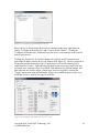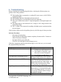
1
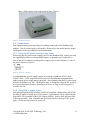
RemKon Edge User Manual www.RemKon.com Copyright 2010 NASCENT Technology, LLC Table of Contents Table of Contents 1 Understanding Your System...................................................................................... 4 1.1 Introduction.......................................................................................................................4 1.2 Major Features..................................................................................................................4 1.2.1 Power ...........................................................................................................................5 1.2.2 Flexible Mounting Options..........................................................................................5 1.2.3 Versatile I/O ................................................................................................................5 1.2.4 Serial Communications................................................................................................6 1.2.5 Remote Access ............................................................................................................6 1.3 Specifications .....................................................................................................................7 2 Selecting your Hardware............................................................................................ 9 2.1 2.2 2.3 2.4 3 Selecting the right Edge model ........................................................................................9 Selecting a power source ..................................................................................................9 Selecting a network connection........................................................................................9 Selecting an interface ......................................................................................................10 Hardware Installation .............................................................................................. 10 3.1 Package Contents ............................................................................................................10 3.2 Placement.........................................................................................................................10 3.3 DIN Rail Mounting .........................................................................................................11 3.4 Wall Mounting ................................................................................................................12 3.5 Connections .....................................................................................................................13 3.5.1 Using the DC power input to supply power ..............................................................13 3.5.2 Using PoE to supply power .......................................................................................13 3.5.3 Using the Relays ........................................................................................................14 3.5.4 Using the Digital Output............................................................................................14 3.5.5 Using the Digital Dry/Wet Contact Input..................................................................14 3.5.6 Using the 5VDC Output ............................................................................................14 3.5.7 Using the Serial Connection ......................................................................................14 4 Edge Model-Specific Instructions............................................................................ 15 4.1 4.2 4.3 5 E124S................................................................................................................................15 E124 ..................................................................................................................................17 E0S2..................................................................................................................................19 System Configuration ............................................................................................... 20 5.1 Initial Network Setup .....................................................................................................20 5.1.1 Microsoft Windows Vista and Windows 7................................................................20 5.1.2 Microsoft Windows XP and 2000 .............................................................................20 5.1.3 Mac OS X ..................................................................................................................21 5.2 Using the Web Manager .................................................................................................22 5.2.1 Accessing Web Manager Through a Web Browser ..................................................23 5.2.2 Understanding the Web Manager Pages....................................................................24 5.2.3 Diagnostics ................................................................................................................25 5.2.4 HTTP Statistics and Configuration............................................................................26 5.2.5 IP Filter ......................................................................................................................27 5.2.6 Lines ..........................................................................................................................28 Copyright 2010, NASCENT Technology, LLC www.RemKon.com 2 5.2.7 LPD............................................................................................................................30 5.2.8 Network .....................................................................................................................30 5.2.9 PPP.............................................................................................................................32 5.2.10 Query Port................................................................................................................33 5.2.11 RemKon Edge IO ....................................................................................................33 5.2.12 RemKon Encryption ................................................................................................34 5.2.13 RemKon SNMP .......................................................................................................35 5.2.14 SNMP ......................................................................................................................35 5.2.15 SSH ..........................................................................................................................36 5.2.16 SSL ..........................................................................................................................37 5.2.17 Syslog ......................................................................................................................38 5.2.18 System .....................................................................................................................38 5.2.19 Terminal...................................................................................................................39 5.2.20 TFTP ........................................................................................................................40 5.2.21 Tunnel ......................................................................................................................40 5.2.22 XML ........................................................................................................................41 5.3 Using the Utilities ............................................................................................................42 5.3.1 RemKon Browser ......................................................................................................42 5.3.2 RemKon Edge Dashboard .........................................................................................44 5.3.3 RemKon Mobile ........................................................................................................47 5.4 Using the SDK .................................................................................................................48 6 Troubleshooting ........................................................................................................ 49 Copyright 2010, NASCENT Technology, LLC www.RemKon.com 3 1 Understanding Your System 1.1 Introduction The RemKon Edge line of Ethernet-based remote devices provides remote I/O and relay control as well as serial-over-IP communications. Models within the RemKon Edge line are equipped with as many as 12 dedicated inputs, 12 dedicated outputs, 4 form C relays, and 2 serial ports. Connecting via 10/100 Ethernet, these devices can be monitored or controlled remotely via a LAN, Intranet, or Internet. Multiple devices can be distributed around a building or plant for automation, control, and monitoring. 1.2 Major Features The RemKon Edge line provides industry standard 10/100 Ethernet connectivity for easy integration into existing networks; as well as simplifying new installs. New connections can be made using Cat5 or better cable with standard RJ45 connections. With full TCP/IP support, managing the RemKon Edge over a network connection is simple and fast. The RemKon Edge line provides a wide array of connectivity and control options. Models are available that include up to 12 5-30VDC tolerant inputs, 12 5VDC outputs, and 4 form C relays. In addition to the I/O options, serial ports are available on equipped models. Serial port options include a single RS232/RS422/RS485 port, and a second RS232 serial port. Copyright 2010, NASCENT Technology, LLC www.RemKon.com 4 Harnessing the power of the RemKon Edge family requires flexible software, and an impressive suite of tools is available to the consumer. Configuration and I/O control may be performed via the embedded web server, or using one of the provided desktop or smartphone tools. System integrators can utilize the available SDK (available for multiple platforms), to integrate the RemKon Edge products into existing or new products. 1.2.1 Power RemKon Edge devices support a wide range of DC voltages (10-30VDC) allowing flexibility in the selection of power supplies and/or integration into existing systems. Some models provide an onboard, low current (500mA) 5VDC output option to power customer supplied devices. For even simpler installation RemKon Edge devices are available with PoE support. Using PoE, a new installation requires only a single Ethernet run and no separate AC or DC power sources (requires usage of PoE Power Sourcing Equipment). On models equipped with PoE, if both PoE and external DC power are supplied the DC power is given priority and the PoE is used as a backup power source. Switching between power sources is automatic and seamless with no downtime or reboot of the device required. 1.2.2 Flexible Mounting Options RemKon Edge devices are built using high quality materials and are designed to be rugged enough to withstand long term use in industrial environments. In addition to a rugged housing, RemKon Edge devices have a variety of mounting options available for greater flexibility in installation. Out of the box the RemKon Edge devices are equally at home on a desk, wall, or DIN rail mounted. Both DIN rail and wall-mount kits are available. The DIN rail mounting attaches quickly and accepts standard 35mm DIN rail. Along with the DIN rail kit, a more traditional wall-mount kit is also available which allows for vertical or horizontal mounting to walls or ceilings. 1.2.3 Versatile I/O RemKon Edge I/O modules provide input, output, and relay functionality. Edge modules are available with 12 inputs and 12 outputs. Each of the inputs is capable of handling wet-contact voltages of 0-30VDC and is internally pulled to ground. Each of the 5VDC digital outputs is capable of sourcing or sinking up to 20mA. The RemKon Edge I/O modules are equipped with 4 form C relays. These relays operate independently from each other and provide access to both normally close and normally open terminals. The relays are capable of handling both AC and DC loads, and are protected with self-resetting fuses that interrupt at 900mA. Copyright 2010, NASCENT Technology, LLC www.RemKon.com 5 1.2.4 Serial Communications RemKon Edge modules are available with up to 2 serial ports. All serialequipped models provide a configurable RS232/422/485 serial port accessible via a DB9 connector. On modules with 2 serial ports the second port only provides RS232. The built-in Web Manger as well as NASCENT Technology's available SDK provides options to configure protocol, baud rate, flow control, and handshaking remotely and on the fly. 1.2.5 Remote Access RemKon Edge modules may be configured via the built-in Web Manger, one of the provided software utilities, or NASCENT Technology's available SDK. The Web Manager provides access from any web-enabled device (PC, Smartphone, etc). NASCENT Technology's SDK may be used to integrate monitoring and control of RemKon Edge devices into a wide variety of applications and software packages. In addition to providing full configuration options, the SDK provides event-based monitoring of the inputs; and full control of both outputs and relays. Copyright 2010, NASCENT Technology, LLC www.RemKon.com 6 1.3 Specifications General Power InputCurrent Requirements PoE Requirements2 Power Output3 LAN LAN Connector Serial4 Serial Connector4 Power Input Connector Power Output Connector3 - 10 to 30VDC 4.0W1 48V (802.3af) (On either set of pairs) 5VDC fused at 500mA 10/100Base-TX RJ-45 1 - RS232/422/485, 1- RS232 only4 DB9 Male (2x on some models) 2 pin header, plug with screw terminals included 2 pin header, plug with screw terminals included Digital Input3 Channels Logic Level 0 Logic Level 1 Connector - 12 Close to GND or Float5 5 to 30VDC 12 pin header, plug with screw terminals included Digital Output3 Channels Logic Level 0 Logic Level 1 Output Max Current Connector - 12 Tied to GND Float 20mA Sink 12 pin header, plug with screw terminals included 1 Power consumed by RemKon Edge module without any devices connected to the 5VDC output. 2 On models with PoE support only. 3 Only available on I/O modules. 4 Not all models include serial functionality, models with 1 port support RS232/422/485 5 Internally pulled to ground with 22kΩ resistor. Copyright 2010, NASCENT Technology, LLC www.RemKon.com 7 Relay Output3 Channels Type Max Hold Current Fuse Trip Current Max Interrupt Current Connector - 4 Form C (SPDT) 400mA @ 240VAC 900mA @ 240VAC 5.5A @ 240VAC, 20A @ 135VAC 12 pin header, plug with screw terminals included Physical Dimension (W x H x D) Enclosure Mounting - 4 x 2 x 4 inches (105 x 50 x 102 mm) ABS Plastic DIN 35 Rail, Stack, Wall Environmental Max Operating Temp Min Operating Temp Storage Temp Range - 158F (70C) 14F(-10C) -40F to 185F (-40C to 85C) Copyright 2010, NASCENT Technology, LLC www.RemKon.com 8 2 Selecting your Hardware Installing a RemKon Edge requires some preparation including selecting the optimal model Edge, selecting a power source, and selecting an interface for configuration. This chapter will aide you in making these decisions. 2.1 Selecting the right Edge model There are a number of different RemKon Edge devices available. Use the table below to find the correct model based on these criteria: - Minimum number of serial ports required. Minimum number of input channels required. Minimum number of output channels required. Are relays required? Is PoE required? Model E124S E124S-P E124 E124-P E0S2 E0S2-P RS232/422/485 Port X X X X RS232 Port X X Output Channels 12 12 12 12 - Input Channels 12 12 12 12 - Relays PoE 4 4 4 4 - X X X 2.2 Selecting a power source All RemKon Edge devices accept a DC power supply with a voltage range of 1030VDC. While the RemKon Edge device requires at least 4W itself; if any additional, customer-supplied equipment will be powered off of the 5VDC output (limited to 500mA), a higher wattage power supply is required. On RemKon Edge models with PoE support, the user has the option of using either PoE of DC power. Equipped models are fully 802.3af compliant and support PoE transmission on either the unused or used pairs. The onboard PoE power regulation system is classified as a Class 0 powered device (PD) and can draw up to 12W from the PoE power sourcing equipment (PSE). When both PoE and DC power are present, the Edge device defaults to DC power and uses the PoE as a backup. If the DC source fails or is removed the Edge device automatically switches to PoE without shutting down or rebooting. 2.3 Selecting a network connection RemKon Edge devices connect to a network via a standard RJ45 female jack. The Edge device is compatible with both 10 and 100 base TX networks with auto negotiation and HP Auto MDIX. For an Ethernet connection, a minimum of Category 3 UTP/STP should be used, however Category 5 (or better) UTP/STP is highly Copyright 2010, NASCENT Technology, LLC www.RemKon.com 9 recommended. All cable and connections should meet EIA/TIA 586 specifications and all cable runs between powered devices should be less than 100m or ~330ft. 2.4 Selecting an interface The RemKon Edge devices may be configured via either the built-in Web Manager, the provided software utilities, or using NASCENT Technology's RemKon SDK. Both require a working network connection. The Web Manager requires a web browser on a computer connected to the same network, while the RemKon SDK requires installation and configuration of the SDK tools. The utilities may be downloaded from www.remkon.com, and installed on a supported computer or mobile device. The web manager, utilities, and SDK are all capable for I/O and relay control. 3 Hardware Installation 3.1 Package Contents Before installing, make sure that the RemKon Edge package includes: - 1 RemKon Edge Module Wall and DIN rail mounting plates 2 Hex studs 1 Hex tool Quick start Guide 3.2 Placement The RemKon Edge modules can be installed in three ways: - They can be placed on a desk or shelf, They can be mounted on a wall or ceiling, and They can be mounted on a DIN rail. Any of these possible locations should provide protection for temperature extremes as well as moisture - the RemKon Edge modules are not designed to be weather proof. When deciding on placement for the RemKon Edge, it is important to take into consideration the connections that will be made to it. If DC power will be used then the RemKon Edge must be located close to a DC power source as well as a network jack or patch cable. Additionally, any I/O or relay lines should be neatly arranged with appropriate strain relief in place. Excessive strain on the connections can reduce the life of the plugs and headers. While the RemKon Edge does not contain any fans or moving parts to attract dust, it is recommended that the modules be installed in protected locations where excessive dust buildup can be avoided. Dust buildup can reduce airflow over the housing and prevent correct cooling of the RemKon Edge. This can shorten the life of the modules. Copyright 2010, NASCENT Technology, LLC www.RemKon.com 10 3.3 DIN Rail Mounting The RemKon Edge modules come with mounting hardware that accepts standard 35MM top hat DIN rail. The Edge’s connectors are conveniently located so as not to interfere with devices mounted on either side of the Edge. The Edge requires approximately 4” of rail. Parallel rails should be spaced at least 10” apart to prevent connector strain. To use the DIN rail mounting kit, begin by attaching the DIN rail mount to the housing: 1. If the hex studs are attached (Figure 1), remove them. If not then locate them in the packaging. Figure 1 - Hex studs installed. 2. Located the DIN rail mounting clip, Figure 2. Figure 2 - DIN Rail Clip. 3. Place the DIN rail clip on the RemKon Edge, aligning the screw holes. The orientation is not critical - the release for the DIN rail clip should be easily Copyright 2010, NASCENT Technology, LLC www.RemKon.com 11 accessible. Insert the hex studs and tighten until snug, Figure 3. Figure 3 - DIN Rail Clip installed. 4. Hang the RemKon Edge by tilting the release away from the DIN rail and slipping the rail into the stationary side. Press the RemKon Edge towards the DIN rail until the release locks over the DIN rail. 3.4 Wall Mounting The RemKon Edge modules come with mounting hardware that allows simple wall or ceiling attachment. The Edge should have at least 2” of space at either end to prevent connector strain. Edge modules may be mounted next to each other with minimal spacing between units. To us the wall mounting kit, begin by attaching the kit to the housing: 1. If the DIN Rail Clip is mounted, remove it by following the steps above in reverse. 2. Locate the hex studs and tighten snugly into the mounting holes on the underside of the RemKon Edge housing. 3. Locate the wall mount plate, Figure 4, and decided on the desired location and orientation. Use the plate as a template, mark the locations for the required anchoring screws/bolts (anchoring holes are at the corners). Figure 4 - Wall mount plate 4. Anchor the wall plate to the wall/ceiling. 5. Attach the wall mount plate in the desired orientation by placing it against the RemKon Edge so that the hex studs protrude thru two of the keyed mounting Copyright 2010, NASCENT Technology, LLC www.RemKon.com 12 holes. Slide it firmly to the side to lock in place, Figure 5. Figure 5 - Wall mount in place. 3.5 Connections This chapter details general procedures for making connections to the RemKon Edge modules. Not all sections apply to all models. Please refer to the model specific images and diagrams in the next chapter for more information. 3.5.1 Using the DC power input to supply power When using the DC power input to supply power to the RemKon Edge, connect (or using the supplied plug with screw terminals)the negative or ground to pin 1 (right side or – side) of the power connector and the positive supply to pin 2 (the left hand or + side) of the power connector, Figure 6. Figure 6 - DC Power Connector. It is important that a power supply capable of providing a minimum of 5W is used. *NOTE: If the +5VDC output will be used to power any additional equipment than a higher wattage power supply must be provided. Also remember that the DC power input will take precedence over PoE. The RemKon Edge is designed to allow the DC power to be removed and replaced with no interruption in service as long as sufficient power is available via PoE. 3.5.2 Using PoE to supply power PoE equipped RemKon Edge modules are 802.3af compliant. When running off of PoE, the Edge is capable of using up to 12W of power. Approximately 5W is required by the Edge and 2.5W is available to the 5VDC output (500mA). Select a PoE injector or PoE switch appropriately. Also, remember that PoE can be used as a backup for DC power input – see the previous section for more info. Copyright 2010, NASCENT Technology, LLC www.RemKon.com 13 3.5.3 Using the Relays There are 4 form C (SPDT) relays on the E124S and E124 RemKon Edge modules. Each relay provides three connections: normally closed (N/C), common (C), and normally open (N/O). 3.5.4 Using the Digital Output The Digital Output consists of 12 open collector outputs that can be tied to ground or float. Logic level 0 corresponds to an internal 20mA sink to ground. Logic level 1 corresponds to the output being in a floating state. Each of the lines can sink up to 20mA. 3.5.5 Using the Digital Dry/Wet Contact Input The Digital Dry/Wet Contact consists of 12 lines. Each input is capable of reading a logic level HIGH at any voltage in the range 5-30VDC. A logic level LOW is read when the line is left open or connected to ground. Each of the lines is tied to ground internally with a 22kOhm resistor. 3.5.6 Using the 5VDC Output Equipped RemKon Edge modules provide a 5VDC output. While this output can be used to power auxiliary devices (the output is fused at 500mA), it is meant primarily to provide a logic level HIGH to the digital input when used with pushbutton or toggle switches (or keypads). The ground terminal can also be used to provide a voltage reference for the digital output. 3.5.7 Using the Serial Connection The serial port on E124S (and COM1 on E0S2) RemKon Edge modules is compatible with both RS232 and RS422/485. The second serial port (COM2) on E0S2 modules is compatible with RS232. The protocol, baud rate, and flow control can be configured via the Line configuration page within the web manager or via the SDK. The pinouts of the DB9 connector are provided in the next chapter, and may be used to create wiring harnesses for a wide array of compatible devices. Copyright 2010, NASCENT Technology, LLC www.RemKon.com 14 4 Edge Model-Specific Instructions 4.1 E124S The RemKon Edge E124S provides 12 input lines, 12 output lines, 4 relays, and 1 RS232/RS485 serial port. It is available with optional PoE support. Below are the diagrams of the front and rear panels. Front Panel Figure 7 - E124S Front Panel 1. DC Power Input Connector, 10-30VDC. Figure 8 - DC Power Connector 2. Relay Connections, 12 pin header with plug. Figure 9 - Relay Connector Copyright 2010, NASCENT Technology, LLC www.RemKon.com 15 3. 10/100 Ethernet and PoE, RJ45 Female Jack. Rear Panel Figure 10 - E124S Rear Panel 1. Digital Dry/Wet Contact Input, 12 pin header with plug. Figure 11 - Digital Input Connector 2. Digital Output, 12 pin header with plug. Figure 12 - Digital Output 3. 5V DC Power Output (500mA), 4 pin header with plug. Figure 13 - 5VDC Power Output Copyright 2010, NASCENT Technology, LLC www.RemKon.com 16 4. COM 1 serial connector, DB9 Male. RS232 TX RX CTS RTS DCD DTR GND RS422/485 TXRX+ RXTX+ GND DB9 Pin #’s 3 2 8 7 1 4 5 4.2 E124 The RemKon Edge E124 provides 12 input lines, 12 output lines, and 4 relays. It is available with optional PoE support. Below are the diagrams of the front and rear panels. Front Panel Figure 14 - E124 Front Panel 1. DC Power Input Connector, 10-30VDC. Figure 15 - DC Power Connector 2. Relay Connections, 12 pin header with plug. Figure 16 - Relay Connector 3. 10/100 Ethernet and PoE, RJ45 Female Jack. Rear Panel Copyright 2010, NASCENT Technology, LLC www.RemKon.com 17 Figure 17 - E124 Rear Panel 1. Digital Dry/Wet Contact Input, 12 pin header with plug. Figure 18 - Digital Input Connector 2. Digital Output, 12 pin header with plug. Figure 19 - Digital Output 3. 5V DC Power Output (500mA), 4 pin header with plug. Figure 20 - 5VDC Power Output Copyright 2010, NASCENT Technology, LLC www.RemKon.com 18 4.3 E0S2 The RemKon Edge E0S2 provides a RS232/RS485 serial port and a RS232 serial port. It is available with optional PoE support. Below is the diagram of the front panel, the rear panel of the E0S2 has no connections. Front Panel Figure 21 - E0S2 Front Panel 1. DC Power Input Connector, 10-30VDC. Figure 22 - DC Power Connector 2. 10/100 Ethernet and PoE, RJ45 Female Jack. Rear Panel Figure 23 - E0S2 Rear Panel 1. COM 1 serial connector, DB9 Male, RS232/RS422/RS485. 2. COM 2 serial connector, DB9 Male, RS232. RS232 TX RX CTS RTS DCD DTR GND RS422/485 TXRX+ RXTX+ GND DB9 Pin #’s 3 2 8 7 1 4 5 Copyright 2010, NASCENT Technology, LLC www.RemKon.com 19 5 System Configuration All the latest firmware and utilities are available on the RemKon website at www.RemKon.com. Before beginning a new device setup, make sure you have the latest tools available. 5.1 Initial Network Setup Before connecting the new RemKon Edge to a network it is important to decide how it will be powered. Edge models equipped with the PoE option can draw power over the network connection (if a suitable PoE injector or PoE switch is used). If a non-PoE model is being installed or a straight DC connection is preferred, connect a power supply capable of supplying 10-30VDC at 5W (it is important to note that if PoE AND DC power are available the Edge will draw power from the DC power and use the PoE as a backup). Please see the chapter on connections for more information on power supply options and requirements. A new RemKon Edge comes preconfigured with DHCP enabled but can be configured several ways. In order to connect to a new RemKon Edge and change the network settings using the web manager the Edge must be connected to a device with the software tools installed (mobile device or desktop version). There are two ways to accomplish this: A. Connect the Edge to an existing network. B. Connect to the Edge directly from a PC or Mac through a crossover cable. If option B is selected then a PC or Mac must be configured with a static IP address such as 192.168.1.1 and on subnet 255.255.255.0 and connected to the Edge through an Ethernet crossover cable. The instructions next may be used to help configure a static IP address. 5.1.1 Microsoft Windows Vista and Windows 7 1. Open the Control Panel. 2. Select "View network status and tasks." 3. Select "Change Adapter Settings" on the left side of the window. 4. Right click on the connection for the desired network card (usually "Local Area Connection") and select properties. 5. Double click "Internet Protocol Version 4" in the list of items. 6. Make a note of your current settings, then change the top radio button to "Use the following IP address:". 7. Enter "192.168.1.1" into the first field (IP address). 8. Enter "255.255.255.0" into the second field (Subnet mask). 9. Click "OK" to close, and click "OK" again to save and close. 5.1.2 Microsoft Windows XP and 2000 1. Open the Control Panel 2. Select "Network Connections" or "Network and Internet Connections." 3. If you selected "Network and Internet Connections" select "Network Connections." Copyright 2010, NASCENT Technology, LLC www.RemKon.com 20 4. 5. 6. 7. 8. 9. Right click on the connection for the desired network card (usually "Local Area Connection") and select properties. Double click "Internet Protocol (TCP/IP)" in the list of items. Make a note of your current settings, then change the top radio button to "Use the following IP address:". Enter "192.168.1.1" into the first field (IP address). Enter "255.255.255.0" into the second field (Subnet mask). Click "OK" to close, and click "OK" again to save and close. 5.1.3 Mac OS X 1. Open System Preferences 2. Select Network 3. Select the desired network card (AirPort for WiFi and Ethernet for a wired connection). 4. Click "Advanced..." 5. Choose the "TCP/IP" tab. 6. Make a note of your current settings, then change "Configure IPv4:" to "Manually." 7. Enter "192.168.1.1" into the "IPv4 Address" field. 8. Enter "255.255.255.0" into the "Subnet Mask" field. 9. Click "OK" 10. Click "Apply" and then quit System Preferences. Once a network connection has been established to the RemKon Edge, perform a search using one of the provided software tools (more details for the individual tools are provided in chapter 5.3). The figures below show the Microsoft Windows version of the RemKon Device Browser. Select the new device and configure it. When prompted for a username and password, enter "admin" and "PASS." Figure 24 - Searching for devices with the RemKon Device Browser. Copyright 2010, NASCENT Technology, LLC www.RemKon.com 21 Figure 25 - Password prompt. Figure 26 - Configuring a device using the RemKon Device Browser. 5.2 Using the Web Manager This chapter describes how to access the RemKon Edge using the web manager, NASCENT’s browser-based configuration tool. The web manager allows both configuration and I/O control. The unit’s configuration is stored in nonvolatile memory and is retained without power. All changes take effect immediately, unless otherwise noted. Copyright 2010, NASCENT Technology, LLC www.RemKon.com 22 5.2.1 Accessing Web Manager Through a Web Browser To access Web Manager: 1. Open a standard web browser (such as Netscape Navigator 6.x and above, Internet Explorer 5.5. and above, Mozilla Suite, Mozilla Firefox, or Opera). 2. Enter the IP address of the RemKon Edge in the address bar. 3. Enter your user name and password. Note: The factory-default username is "admin" and the factory-default password is "PASS." 4. The Web Manager home page displays, Figure 27. Figure 27 - RemKon Edge Home Page (Status Page) Copyright 2010, NASCENT Technology, LLC www.RemKon.com 23 5.2.2 Understanding the Web Manager Pages Figure 28 shows the areas of the Web Manager page and the components of the Web Manager Page. Figure 28 - Understanding the Web Manager pages. - The header always displays at the top of the page. The header information remains the same regardless of the page displayed. The menu bar always displays at the left side of the page, regardless of the page displayed. The menu bar lists the names of the pages available in the Web Manager. To display a page, click it in the menu bar. The main area of the page has from one to three sections: o At the very top, many pages, such as the one in the example above, enable you to link to sub pages. On some pages, you must also select the item you are configuring, such as a line or a tunnel. o In the middle section of many pages, you can select or enter new configuration settings. After you change settings, click the Submit button to apply the change. Some settings require you to reboot the device before the settings take effect. Those settings are identified in the appropriate Copyright 2010, NASCENT Technology, LLC www.RemKon.com 24 - sections in this chapter. Note: Some pages display information such as statistics in this area rather than allow you to enter settings. o The bottom section of most pages shows the current configuration. In some cases you can take an action such as resetting. The information area shows information or instructions associated with the page. The footer displays at the bottom of the page. It contains copyright information and a link to the NASCENT home page. 5.2.3 Diagnostics The diagnostics page, Figure 29, of the RemKon devices provides an overview of several different aspects of the device’s operations – each with it’s own sub-page. Hardware Overview of the CPU and RAM status. Ping Network ping utility. Memory Overview of dynamic memory usage. MIB-II Access to the Management Information Base of the SNMP agent. Traceroute Network traceroute utility. Buffer Pools Overview of the communications buffer usage. Copyright 2010, NASCENT Technology, LLC www.RemKon.com 25 IP Sockets List of all active TCP and UDP sockets. DNS Lookup DNS lookup utility for checking DNS connection. Processes Overview of all active processes on the RemKon device along with stack and CPU allocation. 5.2.4 HTTP Statistics and Configuration The HTTP page provides an overview of the HTTP statistics (Figure 30), and configuration of the username, password, and authentication scheme used by the HTTP server, Figure 31. Figure 29 - HTTP Statistics. Copyright 2010, NASCENT Technology, LLC www.RemKon.com 26 Figure 30 - HTTP Authentication settings The authentication settings page allows the HTTP password and username to be changed, or to add additional users with different permissions. The default username is “admin” with a password of “PASS” using HTTP Digest as an authentication time. If SSL is configured properly, it can be used as the type. To access the Web Manager the URI and Realm should be “/” and “config” which provides access to the Web Manager files on the built-in fileserver. 5.2.5 IP Filter The IP Filter page allows the administrator to restrict access to the Web Manager to specific IP addresses, Figure 32. Figure 31 - IP Filter Table Copyright 2010, NASCENT Technology, LLC www.RemKon.com 27 5.2.6 Lines Lines are the device side of the serial ports. Using the Line statistics page the user can get an overview of the status and current configuration of the RemKon Device’s lines. On E0S2 models, both lines are user configurable. On E124S models, Line 1 refers to the external serial port. On both E124S and E124 models, Line 2 is used for internal communications and should not be changed. A power cycle will fix any inadvertent changes to Line 2. The Line statistics page, Figure 32, show the configuration and status of either line. This includes the amount and direction of data that has been transmitted. This information can help determine if either the network or the serial device are not communicating correctly. Figure 32 - Line statistics page. The Line configuration page allows the user to select baud rate and flow control, as well as the communications protocol to direct to the external line. For remote socket connections, “Tunnel” should be selected. Copyright 2010, NASCENT Technology, LLC www.RemKon.com 28 Figure 33 - Line Configuration page. Copyright 2010, NASCENT Technology, LLC www.RemKon.com 29 5.2.7 LPD The Line Printer Daemon page is available on E124S and E0S2 models, and allows the external serial port to be attached to a printer, with the RemKon device functioning as an LPD printer server, Figure 33. For this to work correctly, the appropriate line will have to be configured with the protocol set to “LPD” on the “Line” page. Figure 34 - LPD Page. 5.2.8 Network The network page is one of the most critical pages for RemKon device configuration. The “Interface” sub pages (shown here) show the TCP/IP network settings and status. The “Link” sub pages show the physical link status and allow configuration of the link speed. The Interface Status page, Figure 35, shows the current TCP/IP network configuration. Copyright 2010, NASCENT Technology, LLC www.RemKon.com 30 Figure 35 - Interface Status page. Copyright 2010, NASCENT Technology, LLC www.RemKon.com 31 The Interface Configuration page, Figure 36, allows the DHCP client to be enabled or disabled, and for a static IP address to be set. It allows the network Hostname and DHCP Client ID to be set. This can help with network management as the DHCP Client ID will be displayed in most DHCP servers’ connected devices lists. NOTE: Changes to network settings only take effect after a reboot. Figure 36 - Interface Configuration page. Static IP addresses are entered into the “IP Address” field using either CIDR notation or fully written out. For example, an IP address of 192.168.1.2 on a class C subnet (255.255.255.0) would be written as “192.168.1.2/24” or “192.168.1.2 255.255.255.0” with a space between the IP and subnet mask. 5.2.9 PPP The external serial lines of the E0S2 and E124S models support PPP. This can be configured through the PPP page, Figure 37. Copyright 2010, NASCENT Technology, LLC www.RemKon.com 32 Figure 37 - PPP Configuration page. 5.2.10 Query Port RemKon devices are discovered on the network by responding to a query on ports 30718 and 30719. To disable device discovery on the network, the query port service can be turned off. The Query Port page, Figure 38, provides the status of the last queries, as well as the ability to turn the service off. Turning the service off makes the device invisible to the RemKon Browser and Edge Dashboard utilities! Figure 38 - Query Port page. 5.2.11 RemKon Edge IO The most flexible control of the E124 and E124S devices’ IO lines is through the RemKon Edge Dashboard software. However, there is a built in Java applet on the devices that provides control and monitoring of the device. It is compatible with all major browsers and operating systems providing they are running Sun Java. The RemKon Edge IO link accesses the Java applet, Figure 39. Once the applet is loaded, click “Connect” to active the applet and start controlling the outputs. Copyright 2010, NASCENT Technology, LLC www.RemKon.com 33 Figure 39 - RemKon Edge IO Java applet. 5.2.12 RemKon Encryption The RemKon IO control occurs over a TCP socket connection. This communication can be raw bytes, or encrypted using 128bit AES. The settings on the encryption page (enabled or not), Figure 40, must match the settings being used in the RemKon Edge Dashboard. The AES key can be manually entered, or randomly generated at every boot up. The keys are exchanged automatically by the Edge Dashboard software if the correct username and password are entered. Figure 40 - RemKon Encryption settings. Copyright 2010, NASCENT Technology, LLC www.RemKon.com 34 5.2.13 RemKon SNMP The RemKon SNMP page, Figure 41, provides 2 functions. First, it allows the inputs and outputs to be named. Once named, the names will appear in the RemKon Edge Dashboard (provided the correct username and password are entered). Second (FUTURE RELEASE), inputs can be designated as SNMP trap generators by checking the checkbox to the right of the input name. Once checked, anytime that input changes it will send an SNMP trap to the designated SNMP trap destination (see SNMP settings, 5.2.14). Figure 41 - RemKon SNMP settings. 5.2.14 SNMP The SNMP page allows the configuration of trap destinations (primary and secondary), SNMP read and write communities, and the device info, Figure 42. Copyright 2010, NASCENT Technology, LLC www.RemKon.com 35 Figure 42 - SNMP configuration and status. 5.2.15 SSH The RemKon devices support SSH for TCP tunneling to the external serial connections. The SSH page allows configuration of SSH, and SSH keys. Copyright 2010, NASCENT Technology, LLC www.RemKon.com 36 Figure 43 - SSH configuration pages. 5.2.16 SSL The RemKon devices support SSL for HTTP authentication. SSL can be configured through the SSL page, Figure 44. Copyright 2010, NASCENT Technology, LLC www.RemKon.com 37 Figure 44 - SSL Configuration page. 5.2.17 Syslog The RemKon devices can be configured to send system and debug log events to a syslog server. The Syslog client is configured using the syslog page, Figure 45. Figure 45 - Syslog client configuration page. 5.2.18 System The System page, Figure 46, on the RemKon devices allows for remote device reboots, firmware upgrades, and naming the device. The name entered into the “long name” field Copyright 2010, NASCENT Technology, LLC www.RemKon.com 38 is used by the RemKon Browser in the device list. The System page also indicates the current firmware version running on the device. Figure 46 - System page. 5.2.19 Terminal The RemKon devices can support a terminal connection to the external serial interface. The terminal page, Figure 47, provides access to configure and monitor a terminal connection. Figure 47 - Terminal configuration page. Copyright 2010, NASCENT Technology, LLC www.RemKon.com 39 5.2.20 TFTP The RemKon devices have a built-in TFTP server which can provide access to the internal filesystem. The TFTP server is configured using the TFTP page, Figure 48. Figure 48 - TFTP page. 5.2.21 Tunnel Connections to serial devices through the RemKon devices are generally done using the Tunnel protocol. Tunneling encapsulates the raw data through a TCP socket connection, and transmits it to and from the external serial device. The Tunnel protocol is configured using the Tunnel page, Figure 49. Settings include which TCP port to listen on, and how to accept connections. Copyright 2010, NASCENT Technology, LLC www.RemKon.com 40 Figure 49 - Tunnel, main page. 5.2.22 XML The internal configurations of the RemKon device are stored in an XML file. Backing up a configuration or importing a configuration can be accomplished through the XML page, Figure 50. Figure 50 - XML Page. Copyright 2010, NASCENT Technology, LLC www.RemKon.com 41 5.3 Using the Utilities NASCENT Technology provides a suite of utilities for using and configuring the RemKon Edge modules. This includes 2 desktop utilities and 1 mobile utility: - - RemKon Device Browser: The RemKon Device Browser software provides a simple way to locate all connected RemKon devices and access the web manager. All RemKon devices are shown, not only Edge modules. RemKon Edge Dashboard: The RemKon Edge Dashboard software package provides the search and configuration functionality of the RemKon Browser package along with I/O control and monitoring. Unlike the RemKon Browser, search results are filtered to only show Edge modules. RemKon Mobile: RemKon Mobile provides the functionality of both the Device Browser and the Edge Dashboard for your mobile device. Any devices in the RemKon family can be configured thru the web manager, and full IO control and monitoring is provided for Edge devices. 5.3.1 RemKon Browser The RemKon Device Browser is a software utility designed to work with all RemKon products. It is intended to provide a fast and simple way to find all RemKon devices connected to a network (or connect to a new device) and facilitate access to the web manager so that the user does not need to keep a list of IP addresses stored anywhere. For this overview, the Windows version of the software is shown. Upon launching the software, the user is greeted with the search results window, Figure 51. Figure 51 - RemKon Device Browser Clicking the "Search..." menu item launches the search options dialog box, Figure 52. This box allows for specific searches by subnet or single IP addresses. It defaults to a "broadcast search," or a total network search. Copyright 2010, NASCENT Technology, LLC www.RemKon.com 42 Figure 52 - RemKon Device Browser Search Dialog Clicking the "Search" button will execute a network search. The results will appear on the left and will indicate the IP address and product type of each RemKon device found, Figure 53. Figure 53 - RemKon Device Browser Search Results When a device is selected out of the list, the "Configure" button enables, providing direct access to the web manager. By default the web manager is loaded to the right of the search results using the operating system's built-in web browser, Figure 54. Figure 54 - Viewing the web manager in the RemKon Device Browser. By default, all RemKon Edge devices are secured. The default security settings are: Username: admin Password: PASS Copyright 2010, NASCENT Technology, LLC www.RemKon.com 43 Trying to configure a secured device will bring up a password prompt, Figure 55. Figure 55 - Secure access to the web manager. For users that prefer a different browser, clicking the "Settings" menu item will bring up a dialog box that disables the built-in view, Figure 56. Disabling the built-in viewer will cause the web manager to open in the system's default web browser. Figure 56 - Enabling/Disabling the built-in viewer. 5.3.2 RemKon Edge Dashboard The RemKon Edge Dashboard provides the same search functionality of the RemKon Device Browser, but the results are filtered to only show Edge products. Along with search functionality and access to the web manager, the Edge Dashboard provides full I/O control and monitoring as well as some I/O power-on state configuration options. Upon launching the Edge Dashboard software, the user is presented with a tabbed view giving access to the search functionality and the I/O control and monitoring. The search tab, Figure 57, provides a search IP address and a "Search" button. The search IP address provides the option of searching for a single IP address, a limited subnet search, or the default - a broadcast, or total network search. Copyright 2010, NASCENT Technology, LLC www.RemKon.com 44 Figure 57 - The RemKon Edge Dashboard Search Tab. When a device is selected from the list, the two buttons on the lower right hand side enable: "Configure in Web Browser" and "Connect for IO Control." Clicking the "Configure in Web Browser" button will open the device's web manager in the system's default web browser. Clicking the "Connect for IO Control" button will switch to the IO Control tab and preload the IP address into the device's IP address field, Figure 58. The IO Control tab is designed to provide monitoring of the 12 input lines as well as full control of all 12 output lines and 4 relays. Light indicators are dark to represent a logic level LOW and are turned on to represent a logic level HIGH. Red indicators are used for outputs, and blue indicators are used for inputs. Output logic levels are toggled by clicking the "Toggle" button next to the desired output. Relay's are considered open for logic level LOW and closed or "picked" for logic level HIGH. Figure 58 - The RemKon Edge Dashboard's IO Control Tab Copyright 2010, NASCENT Technology, LLC www.RemKon.com 45 Rather than using the search function, it is possible to directly enter an IP address into the IP text field. A connection to a RemKon Edge device is initiated by clicking the "Connect" button which will change to a "Disconnect" button while the device is connected or trying to connect. In addition to toggling the output logic levels, the outputs and relays can also be pulsed for a set time interval using the "Timed IO" control on the right of the window. To pulse an output line, select the desired output from the "Output Line" menu and enter a pulse interval in milliseconds. Select the desired logic level of the pulse and initiate the pulse by clicking either the "Pulse High" or "Pulse Low" buttons. This operation will ignore the current logic level of the selected output but will always end the pulse by toggling to the opposite logic level from the selected pulse. If, for instance, output 1 was at logic level LOW and "Pulse Low" was selected for 2000MS than output 1 would stay LOW for 2 sec, and then toggle ending up at logic level HIGH. Using the RemKon Edge Dashboard software, the user can also configure the state of the outputs when the device power's on, or in the event of an unexpected power-cycle (power loss followed by power restored). The RemKon Edge is capable of storing the last used output state and using that state upon power-on, or it can be configured with a static, default state. It is important to note that using the last output state requires that every output change be written to non-volatile EEPROM. The EEPROM is limited to approximately 100000 write cycles so important consideration must be taken on the desired life of the device and the frequency of output changes. For example, if the outputs were changed every 1 sec this would translate to roughly 28 hours of reliable storage. On the other hand, if outputs were only toggled on an hourly basis, the EEPROM should be reliable for over 10 years. Accessing the power-on state is done by clicking the "Power-On State" button. This launches the Power-On State configuration dialog box, Figure 59. Copyright 2010, NASCENT Technology, LLC www.RemKon.com 46 Figure 59 - Power-On Settings Dialog Box. The choices to the user are to use the Last state (top radio button) or a static state, second radio button. The default setting is for all outputs to be turned off. If a static state is configured when the dialog box is opened, the state will be displayed in the "Current Setting" panel. A "0" indicated logic level LOW, and a"1" indicated logic level HIGH. In order to set a new static state, the outputs and relays must be placed in the desired configuration or state using the I/O controls before launching the Power-On Settings dialog box. Once the dialog is open, clicking "Grab Current Output States" will display the new setting. TO SAVE THE NEW STATE you must click "Save and Close," otherwise the new state will not be saved on the device. On the Windows version of the RemKon Edge Dashboard, a taskbar icon provides another means for connecting/disconnecting from the selected device, Figure 60. Notifications are also shown once the devices connects or gets disconnected; or if the Dashboard is not the active application and an input or output line changes logic level. Figure 60 - RemKon Edge Dashboard Taskbar Icon. 5.3.3 RemKon Mobile RemKon Mobile provides the functionality of both the RemKon Device Browser and the Edge Dashboard on a mobile device. Using a WiFi or VPN connection, RemKon Mobile can search for RemKon devices on a network. RemKon mobile provides access to more detailed information about discovered devices, as well as quick access to the web manager. For Edge devices, and IO control dashboard is also available. Copyright 2010, NASCENT Technology, LLC www.RemKon.com 47 Upon launching RemKon Mobile, the user is presented with a search results screen, . Tapping the "Search" button performs a broadcast search. Alternatively, tapping the "+" button allows the user to search for a specific IP address and will only display the first result, . Discovered devices are sorted by type and both the type and IP address are displayed in the list. Tapping a device in the list moves to a sub view that gives more detailed information, such as the device's MAC address, and access to the web manager or IO dashboard (for Edge devices only), . Tapping the web manager button will launch the mobile device's web browser and open the selected RemKon's web manager page. Tapping the IO control button will access the IO dashboard for a selected Edge device, . Similar to the RemKon Edge Dashboard, RemKon Mobile's IO dashboard has a connect button, toggle buttons, and red and blue indicators to indicate logic levels on input and output lines. Tapping the "Connect" button will connect to the selected Edge Device and the button will change to "Connected." Tapping the button again, or the back button will close the connection. 5.4 Using the SDK The Software Development Kit (SDK) allows the RemKon Edge modules to be integrated into new or existing software. It provides full control of the input and output lines, relays, and the serial ports. The SDK consists of a set of Application Programming Interfaces (APIs) that are platform independent and expose control to the different capabilities of the RemKon Edge modules. For detailed API and usage information please see the RemKon Edge SDK user manual and API reference guide. Copyright 2010, NASCENT Technology, LLC www.RemKon.com 48 6 Troubleshooting Before consulting the troubleshooting table below, checking the following items can quickly resolve many problems. The RemKon Edge is connected to a working DC power source (or PoE PSE for equipped modules). The RemKon Edge has a link light on the network jack. The Web Manager is accessible thru the network connection. There are no shorts between the 5V output and ground, or the digital outputs and ground. The digital inputs are not connected to AC voltage or a DC voltage outside of the rated voltage range. The 5V output is not connected to anything with higher power requirements than the rated output. If the list above did not resolve the problem please try the following safe-boot procedure: Safe-boot Procedure: - Disconnect all connections Ensure that the RemKon Edge remains completely disconnected for 5 minutes to allow all circuits to discharge. Reconnect ONLY power and LAN Check for LAN link light and Web Manager access. If the above suggestions and procedure did not apply or solve the issue, you can consult the symptom/remedy table below. Symptom No link light/no network access Link light but no Web Manager access Digital Input does not read HIGH. Digital Input does not read LOW. Relay is not making connection. Remedy 1. Verify that the LAN connection is working (test with another device). 2. Test with DC if using PoE, verify DC power is correct if using DC. 3. Try safe-boot procedure above. Verify IP and Subnet are correct on both the RemKon Edge and the host computer. A HIGH must be in the correct voltage range. Test the input line by making a direct connection to the 5VDC output. If a HIGH is read correctly then the voltage being attached is not high enough. The RemKon Edge provides internal pulldown resistors. Verify that the line reads LOW with nothing attached. If a LOW is read correctly, then the attached voltage is not going low enough. The relays are fused with resettable fuses. Copyright 2010, NASCENT Technology, LLC www.RemKon.com 49 Serial port reads or sends nothing or incorrect characters 5VDC output does not work Try the safe-boot procedure above then test for correct connectivity between the relay terminals using a continuity-meter. 1. Verify protocol if using COM1 2. Verify port settings (baud rate, flow control, etc). The 5VDC output is fused with a resettable fuse. Try the safe-boot procedure then test with a volt-meter. Copyright 2010, NASCENT Technology, LLC www.RemKon.com 50