1
GT Converter2
Version 2
Operating Manual
SW2D5C-GTWK2-E
SW2D5C-GTD2-E
SAFETY PRECAUTIONS
(Be sure to read these instructions before using the product)
Before using this product, read this manual and the relevant manuals introduced in this manual carefully
and handle the product correctly with full attention to safety.
Note that these precautions apply only to this product.
In this manual, the safety instructions are ranked as "WARNING" and "CAUTION".
WARNING
Indicates that incorrect handling may cause hazardous conditions, resulting in
death or severe injury.
CAUTION
CAUTION Indicates that incorrect handling may cause hazardous conditions,
resulting in minor or moderate injury or property damage.
Note that failure to observe the
CAUTION level instructions may also lead to serious results
depending on the circumstances.
Be sure to observe the instructions of both levels to ensure personal safety.
Please keep this manual in accessible place and be sure to forward it to the end user.
[Precaution for Conversion]
Caution
All project data conversion for the GOT1000 or GOT-A900 series using GT Converter2 shall not be
guaranteed.
Before downloading converted project data to the GOT, be sure to check the settings with GT
Designer2 and correct them if necessary.
Failure to do so can lead to malfunction.
A-1
Cautions for using this software
1. Required PC memory
The processing may be terminated by Windows® on a personal computer of which main memory capacity is
less than 64M bytes. Make sure to secure the capacity of 64 M bytes or more.
2. Free capacity of hard disk (virtual memory)
At least 50M bytes of free capacity of virtual memory should be secured within hard disk to run this software.
The processing may be terminated by Windows®, if 50M bytes or more of free space cannot be secured
within hard disk while running GT Designer.
Secure enough free capacity of virtual memory within hard disk space in order to run the software.
When enough free capacity cannot be secured, make sure to save projects frequently.
3. Error messages displayed while starting and editing
"Insufficient memory."
If the above message appears, close other running application software or reboot Windows in order to
secure at least 50M bytes of free hard disk space.
4. OS setting
Set the font size as "Small Font" when setting OS (Windows®) screen.
The GT designer2 dialog box cannot be displayed correctly if the font size is set as "Large font".
A-2
REVISIONS
* The manual number is given on the left bottom of the back cover.
Print Date
*Manual Number
Revision
Oct., 2004
SH(NA)-080533ENG-A
First Printing
Mar., 2005
SH(NA)-080533ENG-B
Compatible with GT Converter2 Version2.09K.
Partial corrections
Section 1.1, 3.1, 4.1.1, 4.1.2, 4.2, 4.4, 5.3, 5.3.2, 5.4,
Appendix 1, 2, 2.2, 2.3, 2.6
Additions
Appendix 3
Jan., 2006
SH(NA)-080533ENG-C
Compatible with GT Converter2 Version 2.27D
Partial corrections
Appendix 2.2, 2.8, 3
Jun., 2006
SH(NA)-080533ENG-D
Partial corrections
Appendix 2.1
Nov., 2006
SH(NA)-080533ENG-E
Compatible with GT Converter2 Version 2.43V
Partial corrections
Section 5.3.2, Appendix 2.1, 2.2, 2.6, 2.7, 3
Dec., 2007
SH(NA)-080533ENG-F
Compatible with GT Converter2 Version 2.73B
Partial corrections
Section 1.1, 3.1, 4.1.2, 5.3, 5.3.2, Appendix 2.5
Partical additions
Section 3.1, 5.4.1, Appendix 1.2, 2.6, 2.7, 3
Feb., 2008
SH(NA)-080533ENG-G Compatible with GT Converter2 Version 2.77F
Partial corrections
Section 5.4, Appendix 3
Partical additions
Section 5.4.1
Jun., 2008
SH(NA)-080533ENG-H
Compatible with GT Converter2 Version 2.82L
Partial corrections
Section 2.1, 2.2, Appendix 1.2
Partical additions
Chapter 1, Section 5.4.1, Appendix 3
Oct., 2010
SH(NA)-080533ENG-I
Additions
Appendix 3
Sep., 2012
SH(NA)-080533ENG-J
Additions
SAFETY PRECAUTIONS changed, Appendix 2.5
Japanese Manual Version SH-080512-K
This manual confers no industrial property rights or any other kind, nor does it confer any patent licenses. Mitsubishi Electric
Corporation cannot be held responsible for any problems involving industrial property rights which may occur as a result of
using the contents noted in this manual.
2004 MITSUBISHI ELECTRIC CORPORATION
A-3
INTRODUCTION
Thank you for purchasing Mitsubishi Graphic Operation Terminal (Mitsubishi GOT).
Prior to use, read this manual to fully understand the functions and performance of the GOT.
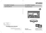
CONTENTS
SAFETY PRECAUTIONS . . . . . . . . . . . . . . . . . . . . . . . . . . . . . . . . . . . . . . . . . . . . . . . . . . . . . . . . . . . . . . . . A - 1
REVISIONS . . . . . . . . . . . . . . . . . . . . . . . . . . . . . . . . . . . . . . . . . . . . . . . . . . . . . . . . . . . . . . . . . . . . . . . . . . . A - 3
INTRODUCTION . . . . . . . . . . . . . . . . . . . . . . . . . . . . . . . . . . . . . . . . . . . . . . . . . . . . . . . . . . . . . . . . . . . . . . . A - 4
CONTENTS . . . . . . . . . . . . . . . . . . . . . . . . . . . . . . . . . . . . . . . . . . . . . . . . . . . . . . . . . . . . . . . . . . . . . . . . . . . A - 4
Manuals . . . . . . . . . . . . . . . . . . . . . . . . . . . . . . . . . . . . . . . . . . . . . . . . . . . . . . . . . . . . . . . . . . . . . . . . . . . . . . A - 6
Abbreviations and Generic Terms . . . . . . . . . . . . . . . . . . . . . . . . . . . . . . . . . . . . . . . . . . . . . . . . . . . . . . . . . . A - 7
How to use this manual . . . . . . . . . . . . . . . . . . . . . . . . . . . . . . . . . . . . . . . . . . . . . . . . . . . . . . . . . . . . . . . . . . A - 9
1. OUTLINE
1.1
Features
2. SYSTEM CONFIGURATION
1-1
2 - 1 to 2 - 2
2.1
System Configuration
2-1
2.2
Operating Environment
2-1
3. SPECIFICATIONS
3.1
Compatible File Formats
4. GT CONVERTER2 SCREEN LAYOUT
4.1
Screen Layout and Basic Operations
4.1.1
4.1.2
A-4
1 - 1 to 1 - 2
3 - 1 to 3 - 2
3-1
4 - 1 to 4 - 4
4-1
Screen layout. . . . . . . . . . . . . . . . . . . . . . . . . . . . . . . . . . . . . . . . . . . . . . . . . . . . . . . . . . . . 4 - 1
Basic operations . . . . . . . . . . . . . . . . . . . . . . . . . . . . . . . . . . . . . . . . . . . . . . . . . . . . . . . . . 4 - 1
4.2
Menu Bar
4-2
4.3
Toolbar
4-2
4.4
How to use Help
4-3
5. GT CONVERTER2 OPERATION METHODS
5 - 1 to 5 - 19
5.1
Operating Procedures
5-1
5.2
Opening Conversion Source File
5-2
5.3
Conversion
5-4
5.3.1
5.3.2
5.4
Checking Conversion Result
5.4.1
5.5
Output directory setting . . . . . . . . . . . . . . . . . . . . . . . . . . . . . . . . . . . . . . . . . . . . . . . . . . . . 5 - 5
Conversion option settings . . . . . . . . . . . . . . . . . . . . . . . . . . . . . . . . . . . . . . . . . . . . . . . . . . 5 - 6
Conversion log list . . . . . . . . . . . . . . . . . . . . . . . . . . . . . . . . . . . . . . . . . . . . . . . . . . . . . . . . 5 - 9
Exiting GT Converter2
APPENDICES
Appendix 1
5-7
Conversion Specifications for GOT800 Series
5 - 19
App- 1 to App - 38
App- 1
Appendix 1.1 Graphics Conversion specification . . . . . . . . . . . . . . . . . . . . . . . . . . . . . . . . . . . . . . . . App- 1
Appendix 1.2 Conversion specifications for sprites . . . . . . . . . . . . . . . . . . . . . . . . . . . . . . . . . . . . . . App- 2
Appendix 2
Conversion Specifications for GP-PRO/PB III Series
Appendix 2.1
Appendix 2.2
Appendix 2.3
Appendix 2.4
Appendix 2.5
Appendix 2.6
Appendix 2.7
Appendix 2.8
Appendix 2.9
App- 4
Conversion specifications of project data . . . . . . . . . . . . . . . . . . . . . . . . . . . . . . . . . . . App- 4
GP type . . . . . . . . . . . . . . . . . . . . . . . . . . . . . . . . . . . . . . . . . . . . . . . . . . . . . . . . . . . . App- 10
PLC type . . . . . . . . . . . . . . . . . . . . . . . . . . . . . . . . . . . . . . . . . . . . . . . . . . . . . . . . . . . App- 13
Screen information . . . . . . . . . . . . . . . . . . . . . . . . . . . . . . . . . . . . . . . . . . . . . . . . . . . App- 15
Graphic data . . . . . . . . . . . . . . . . . . . . . . . . . . . . . . . . . . . . . . . . . . . . . . . . . . . . . . . . App- 15
Tag information . . . . . . . . . . . . . . . . . . . . . . . . . . . . . . . . . . . . . . . . . . . . . . . . . . . . . . App- 16
Parts information. . . . . . . . . . . . . . . . . . . . . . . . . . . . . . . . . . . . . . . . . . . . . . . . . . . . . App- 19
D-Script . . . . . . . . . . . . . . . . . . . . . . . . . . . . . . . . . . . . . . . . . . . . . . . . . . . . . . . . . . . . App- 20
LS area . . . . . . . . . . . . . . . . . . . . . . . . . . . . . . . . . . . . . . . . . . . . . . . . . . . . . . . . . . . . App- 25
Appendix 3 Procedure to Convert GP-PRO/PB III Series Project Data
App - 27
Appendix 3.1 Conversion procedure. . . . . . . . . . . . . . . . . . . . . . . . . . . . . . . . . . . . . . . . . . . . . . . . .App - 27
Appendix 3.2 GP2000 system data . . . . . . . . . . . . . . . . . . . . . . . . . . . . . . . . . . . . . . . . . . . . . . . . .App - 34
Appendix 4
List of functions added by GT Converter2 version update
App- 38
A-5
Manuals
The following table lists the manual relevant to this product.
You can order it as necessary.
Related Manuals
Manual Number
Manual Name
(Type code)
GT Designer2 Version2 Basic Operation/Data Transfer Manual (for GOT1000 Series)
Describes methods of the GT Designer2 installation operation, basic operation for drawing and transmitting
SH-080529ENG
(1D7M24)
data to GOT1000 series.
(Sold separately)*1
GT Designer2 Version2 Screen Design Manual (for GOT1000 Series) 1/3
GT Designer2 Version2 Screen Design Manual (for GOT1000 Series) 2/3
SH-080530ENG
GT Designer2 Version2 Screen Design Manual (for GOT1000 Series) 3/3
(1D7M25)
Describes specifications and settings of the object functions used in GOT1000 series.
(Sold separately)*1
GT Designer2 Version2 Operating Manual (Startup Introductory Manual)
Explains how to install GT Designer2 and screen editing methods for novice GOT900 series users.
(Sold separately)*1
(Sold separately)*1
GT Designer2 Version2 Reference Manual
Provides specifications and setting details of various object functions used in GOT900 series.
(Sold separately)*1
*1
A-6
Included with GT Works2 and GT Designer2 in PDF format.
(1DM215)
SH-080521ENG
GT Designer2 Version2 Operating Manual
Explains how to operate GT Designer2 and how to transfer data to GOT900 series.
SH-080520ENG
(1DM216)
SH-080522ENG
(1DM217)
Abbreviations and Generic Terms
Abbreviations and generic terms used in this manual are as follows:
GOT
Abbreviations and generic terms
GT SoftGOT1000
Abbreviation of GT SoftGOT1000
GT1595
GT1595-X
Abbreviation of GT1595-XTBA, GT1595-XTBD
GT1585V-S
Abbreviation of GT1585V-STBA
GT1585-S
Abbreviation of GT1585-STBA, GT1585-STBD
GT1575V-S
Abbreviation of GT1575V-STBA
GT1575-S
Abbreviation of GT1575-STBA, GT1575-STBD
GT1575-V
Abbreviation of GT1575-VTBA, GT1575-VTBD
GT1575-VN
Abbreviation of GT1575-VNBA, GT1575-VNBD
GT1572-VN
Abbreviation of GT1572-VNBA, GT1572-VNBD
GT1565-V
Abbreviation of GT1565-VTBA, GT1565-VTBD
GT1562-VN
Abbreviation of GT1562-VNBA, GT1562-VNBD
GT1555-V
Abbreviation of GT1555-VTBD
GT1555-Q
Abbreviation of GT1555-QTBD, GT1555-QSBD
GT1550-Q
Abbreviation of GT1550-QLBD
GT1585
GT157
GT156
GOT1000
Description
GT155
Series
GT15
GT115
, GT15
GT1155-Q
GT1150-Q
Abbreviation of GT1595, GT1585, GT157
GT1155-QSBDA, GT1155-QSBD
Abbreviation of GT1150-QLBDQ, GT1150-QLBDA, GT1150-QLBD
GT1155HS-Q Abbreviation of GT1155HS-QSBD
GOT
GT1150HS-Q Abbreviation of GT1150HS-QLBD
, GT11
Abbreviation of GT1155-Q, GT1150-Q, GT11 Handy GOT
Abbreviation of GT1030-LBD, GT1030-LBD2, GT1030-LBDW, GT1030-
GT1030
LBDW2
Abbreviation of GT1020-LBD, GT1020-LBD2, GT1020-LBL, GT1020-
GT1020
GT10
, GT155
Abbreviation of GT1155-QTBDQ, GT1155-QSBDQ, GT1155-QTBDA,
Handy
GT11
, GT156
LBDW, GT1020-LBDW2, GT1020-LBLW
, GT10
Abbreviation of GT1030, GT1020
GOT900 Series
Abbreviation of GOT-A900 series, GOT-F900 series
GOT800 Series
Abbreviation of GOT-800 series
A-7
Software
Abbreviations and generic
Description
terms
Abbreviation of data conversion software GT Converter2 for GOT1000/GOT900
GT Converter2
series
GT Works2 Version
SW
D5C-GTWK2-E, SW
GT Designer2 Version
SW
D5C-GTD2-E, SW
GT Designer2
Abbreviation of screen drawing software GT Designer2 for GOT1000/GOT900 series
GT Simulator2
Abbreviation of screen simulator GT Simulator 2 for GOT1000 / GOT900 series
GT SoftGOT1000
Abbreviation of monitoring software GT SoftGOT1000
GT SoftGOT2
Abbreviation of monitoring software GT SoftGOT2
Abbreviation of SW
GX Developer
D5C-GTWK2-EV
D5C-GTD2-EV
D5C-GPPW-E(-EV)/SW
D5F-GPPW-E type software
package
Abbreviation of SW
GX Simulator
D5C-LLT-E(-EV) type ladder logic test tool function software
packages (SW5D5C-LLT (-EV) or later versions)
PX Developer
Abbreviation of SW
Document Converter
D5C-FBDQ-E type FBD software package for process control
Abbreviation of document data conversion software Document Converter for
GOT1000 series
DU/WIN
Abbreviation for PX-PCS-DU/WIN
SW3NIW-A8GOTP
SW3NIW-A8GOTP Graphic Settings Software Package
Generic term for
GP-PRO/PB
Series
GP-PRO/PB
(DOS Version),
GP-PRO/PB
for Windows95,
GP-PRO/PB
for Windows,
GP-PRO/PB
C-Package01,
GP-PRO/PB
C-Package02 and
GP-PRO/PB
C-Package03
Other
Abbreviations and generic terms
Computer
A-8
Description
Generic term for IBM PC/AT -compatible personal computer (Including PC98-NX )
How to use this manual
1 Functions
This manual describes functions available for the GT Converter2 Version2.82L.
For the added functions by the product version upgrade, refer to the list of functions added by GT
Converter2 version upgrade in Appendices.
2 Symbols
Following symbols are used in this manual.
....
Indicates the operation steps.
Brackets used for the menu and items differ.
: Refers to an item displayed on the
computer screen or the GOT screen.
: Refers to a button displayed on the
computer screen or the GOT screen,
or a key of the computer keyboard.
Shows the items including detailed
explanation (manual and its chapter,
section, item).
Point
Refers to information required
for operation.
Refers to information useful
for operation.
Remark
Refers to supplementary
explanations.
*The above is user for explanation only and differs from the actual page.
A-9
Memo
A - 10
1
OUTLINE
1. OUTLINE
This manual explains the specifications and operation methods of GT Converter2.
2
Installation method of GT Converter2
SYSTEM
CONFIGURATION
For the installation method of GT Converter2, refer to the following manuals.
GT Designer2 Version Basic Operation/Data Transfer Manual
(2.2 Installing the Software Programs)
1.1 Features
GT Converter2 is software that converts project data created by existing screen editor software into those
available for use on GT Designer 2.
1 Compatible with Digital Electronics Corporation's screen editor software
•••••••••••••••••
Section 3.1 Compatible File Formats
SPECIFICATIONS
3
Project data created by Digital Electronics Corporation's GP-PRO/PB series screen editor software
can be converted into GT Designer2 project data (for the GOT1000 or GOT-A900).
GT CONVERTER2
SCREEN LAYOUT
4
GP-PRO/PB
series
GT Converter2
GT CONVERTER2
OPERATION METHODS
5
GT Designer2
The GOT1000 or GOT-A900 series can be selected as a GOT type.
APPENDICES
2 Compliance with GOT800 series screen editor software
•••••••••••••••••
Section 3.1 Compatible File Formats
Project data created by the GOT800 series screen editor software, SW3NIW-A8GOTP, can be
converted into GT Designer 2 project data (for the GOT1000 or GOT-A900).
SW3NIW-A8GOTP
GT Converter2
GT Designer2
The GOT1000 or GOT-A900 series can be selected as a GOT type.
1.1 Features
1-1
3 Outputting conversion logs
•••••••••••••••••
Section 5.4 Checking Conversion Result
The conversion logs (conversion results) can be displayed on the screen and saved as a text file.
If a conversion failure occurs, the cause of the failure can be checked on the conversion logs.
Convertion failure!
1-2
1.1 Features
1
OUTLINE
2. SYSTEM CONFIGURATION
Because GT Converter2 is installed into the same computer where GT Designer2 is installed, the system
configuration is the same as that of GT Designer2.
System Configuration • • •
GT Designer2 Version Basic Operation/Data Transfer
Manual
(Section 1.5 System Configuration)
3
Item
Description
Personal computer
PC/AT compatible personal computer that Windows® runs on
SPECIFICATIONS
2.2 Operating Environment
Microsoft® Windows® 98 Operating System
4
(English, Simplified Chinese, Traditional Chinese, Korean, German versions)
Microsoft
®
Windows®
Millennium Edition Operating System
GT CONVERTER2
SCREEN LAYOUT
(English, Simplified Chinese, Traditional Chinese, Korean, German versions)
Microsoft® Windows NT® Workstation 4.0 Operating System
(English, Simplified Chinese, Traditional Chinese, Korean, German versions)*1
Microsoft® Windows® 2000 Professional Operating System
(English, Simplified Chinese, Traditional Chinese, Korean, German versions)*1
5
GT CONVERTER2
OPERATION METHODS
Microsoft® Windows® XP Professional Operating System
(English, Simplified Chinese, Traditional Chinese, Korean, German versions)*1 *2 *3
Microsoft® Windows® XP Home Edition Operating System
Operating system
2
SYSTEM
CONFIGURATION
2.1 System Configuration
(English, Simplified Chinese, Traditional Chinese, Korean, German versions)*1 *2 *3
Microsoft® Windows Vista® Ultimate Operating System
(English, Simplified Chinese, Traditional Chinese, Korean, German versions)*1 *2 *3
Microsoft® Windows Vista® Enterprise Operating System
(English, Simplified Chinese, Traditional Chinese, Korean, German versions)*1 *2 *3
Microsoft® Windows Vista® Business Operating System
APPENDICES
(English, Simplified Chinese, Traditional Chinese, Korean, German versions)*1 *2 *3
Microsoft® Windows Vista® Home Premium Operating System
(English, Simplified Chinese, Traditional Chinese, Korean, German versions)*1 *2 *3
Microsoft® Windows Vista® Home Basic Operating System
(English, Simplified Chinese, Traditional Chinese, Korean, German versions)*1 *2 *3
Computer
CPU
Refer to "Applicable operating system and performance required for personal computer" on the next page.
Memory
For installation: 10MB or more
Hard disk space
For execution: 50MB or more
Disk drive
CD-ROM drive
Display color
High Color (16 bits) or more
Display*3
Resolution 800
600 dots or more
Internet Explorer 5.0 or later must be installed.
Others
The mouse, keyboard, printer, and CD-ROM drive must be compatible with the above OS.
*1:
Administrator authority is required for installing GT Converter2.
2.1 System Configuration
2-1
*2:
*3:
The following functions are not supported.
• "Compatibility mode"
• "Fast user switching"
• "Change your desktop themes (fonts)"
• "Remote desktop"
Only the 32-bit OS is available.
Applicable operating system and performance required for personal computer
Operating system
Performance required for personal computer
CPU
Memory
Pentium® 200MHz or more
64MB or more
Pentium® 200MHz or more
64MB or more
Pentium® 200MHz or more
64MB or more
Pentium® 200MHz or more
64MB or more
Pentium II® 300MHz or more
128MB or more
Microsoft® Windows® 98 Operating System
(English, Simplified Chinese, Traditional Chinese, Korean, German
versions)
Microsoft® Windows® Millennium Edition Operating System
(English, Simplified Chinese, Traditional Chinese, Korean, German
versions)
Microsoft® Windows NT® Workstation 4.0 Operating System
(English, Simplified Chinese, Traditional Chinese, Korean, German
versions)
Microsoft® Windows® 2000 Professional Operating System
(English, Simplified Chinese, Traditional Chinese, Korean, German
versions)
Microsoft® Windows® XP Professional Operating System
(English, Simplified Chinese, Traditional Chinese, Korean, German
versions)
Microsoft® Windows® XP Home Edition Operating System
(English, Simplified Chinese, Traditional Chinese, Korean, German
versions)
Microsoft® Windows Vista® Ultimate Operating System
(English, Simplified Chinese, Traditional Chinese, Korean, German
versions)
Microsoft® Windows Vista® Enterprise Operating System
(English, Simplified Chinese, Traditional Chinese, Korean, German
versions)
Microsoft® Windows Vista® Business Operating System
(English, Simplified Chinese, Traditional Chinese, Korean, German
versions)
Microsoft®
Windows
Vista®
Home Premium Operating System
(English, Simplified Chinese, Traditional Chinese, Korean, German
versions)
Microsoft® Windows Vista® Home Basic Operating System
(English, Simplified Chinese, Traditional Chinese, Korean, German
versions)
2-2
2.2 Operating Environment
800MHz or more
512MB or more
(Recommended: 1GHz or
(Recommended: 1GB or
more)
more)
1
OUTLINE
3. SPECIFICATIONS
3.1 Compatible File Formats
2
SYSTEM
CONFIGURATION
This section explains GT Converter2 compatible file formats before and after conversion.
1 Conversion source file format
conversion source
SPECIFICATIONS
3
GT Converter2
4
GT Designer2
GT CONVERTER2
SCREEN LAYOUT
SW3NIW-A8GOTP/
GP-PRO/PB series
(1) Digital Electronics Corporation's screen editor software
The following can be specified as conversion source file formats.
Screen editor software
for Windows
GP-PRO/PB
C-Package01
GP-PRO/PB
C-Package02
GP-PRO/PB
C-Package03
GP-PRO/PB
(DOS Version)
5
GT CONVERTER2
OPERATION METHODS
for Windows95
GP-PRO/PB
ProPB/Win project format (*.prw)
ProPB/DOS project format (*.pro)
Precautions for converting project data created by screen editor software from Digital
Electronics Corporation
When project data created by the screen editor software of GP-PRO/PB series
from Digital Electronics Corporation are not correctly converted, open and save the
data again with the software, and then convert the data. As a result, the data may be
correctly converted.
For details on the screen editor software of GP-PRO/PB
Digital Electronics Corporation, refer to the following.
Manual for GP-PRO/PB
Corporation
series manufactured by
series manufactured by Digital Electronics
3.1 Compatible File Formats
3-1
APPENDICES
GP-PRO/PB
File format
(2) GOT800 Series screen editor software
The following can be specified as a conversion source file format.
Screen editor software
File format
SW3NIW-A8GOTP
Remark
GOT800 Format (a8gotp.got)
To Reuse Project Data Created for A64GOT or A77GOT
Using SW3NIW-A8GOTP, convert the project data for A64GOT or A77GOT into
GOT800 file format.
The project data in GOT800 format can be converted into GT Designer2 project data
using GT Converter2.
Refer to the following manual for the details.
SW3NIW-A8GOTP Graphic Settings Software Package Operating
Manual (Monitor Screen Creation Manual) (IB-66793) (Section 2.5 Using
Previously Created GOT Data)
2 File format after conversion
after conversion
SW3NIW-A8GOTP/
GP-PRO/PB series
GT Converter2
GT Designer2
The following can be specified for the file formats after conversion.
Manufacturer
Mitsubishi Electric
Corporation
Remark
Screen editor software
GT Designer2
File format
GOT1000 Format (*.g1)
GOT-A900 Format (A9GOTP.GOT)
Data Size of Converted File
When checking the data size of the file after conversion, save the project data on GT
Designer2 once, and then re-open the saved project data.
The data size may not be displayed properly if this is not performed.
3-2
3.1 Compatible File Formats
4.1 Screen Layout and Basic Operations
2
Screen layout
SYSTEM
CONFIGURATION
4.1.1
1
OUTLINE
4. GT CONVERTER2 SCREEN LAYOUT
The screen is laid out as shown below.
Title bar
Menu bar
Toolbar
3
Section 4.2
4.2 Menu
Menu bar
Bar
Section
SPECIFICATIONS
Section
Section4.3
4.3Toolbar
Toolbar
GT CONVERTER2
SCREEN LAYOUT
4
5
4.1.2
GT CONVERTER2
OPERATION METHODS
Dropdown menu
Basic operations
(1) Check box
To execute an item, click
to put the
mark.
(2) Radio button
(1) Check box
Click
for the item to be selected.
(2) Radio button
4.1 Screen Layout and Basic Operations
4.1.1 Screen layout
4-1
APPENDICES
Basic operations are explained here.
4.2 Menu Bar
The following commands are provided on the menu bar.
Project
From the Project menu, project data can be opened and GT
Converter2 can be exited.
Chapter 5. GT CONVERTER2 OPERATION
METHODS
Conversion
From he Conversion menu, the conversion settings screen can be
displayed.
Chapter 5. GT CONVERTER2 OPERATION
METHODS
Help
The help menu contains functions of viewing the PDF manual related
to the GT Designer2 and checking the software version.
Section 4.4 How to use Help
4.3 Toolbar
The following toolbar are provided.
Name
4-2
Content
Open
Opens a conversion source file.
Start
Used to make conversion settings and perform conversion.
4.2 Menu Bar
Help is used for referring to the GT Designer2-relevant manual (PDF format) and confirming the software
version.
Before viewing PDF format manual
2
SYSTEM
CONFIGURATION
To view the PDF manual, GT Manual and Adobe® Reader® is required to be
installed.
1 Operation method
1 Click on each menu item under [Help].
3
Description
[Index (GOT 1000)], [Index (GOT900)]
This item is used for viewing a PDF manual.
[About GT Converter2...]
This item is used for confirming the GT Converter2 version.
[Connect to MELFANSweb...]
SPECIFICATIONS
Item
OUTLINE
1
4.4 How to use Help
This item is used for connecting to the MITSUBISHI ELECTRIC FA NETWORK
SERVICE ON WORLD WIDE, MELFANSweb homepage
4
GT CONVERTER2
SCREEN LAYOUT
2 PDF manual viewing procedure
(When [Index (GOT1000)] / [Index (GOT900)] is selected.)
1 After operation in 1 , the screen shown below is displayed. Click the manual you want to view.
GT CONVERTER2
OPERATION METHODS
5
Click
*The above is user for explanation only and differs from the actual page.
APPENDICES
2 The selected manual is displayed.
(For details of the Adobe® Reader® operation method, refer to the help of Adobe® Reader®.)
Switches the display
to the first page of
the selected item
Returns to INDEX MENU.
*The above is user for explanation only and differs from the actual page.
4.4 How to use Help
4-3
3 Clicking the icon on the bottom-right corner of the INDEX MENU switches the screen between the
GOT1000 and GOT900 series manuals.
Click here when viewing
from the CD-ROM.
Click here when viewing
the installed manual.
(Example : Screen displayed when changing to the GOT900 Series)
3 GT converter2 version check procedure (When selecting [About GT Converter2...])
1 After operation in 1 , the Version Information screen is displayed.
(Example: When the version is 2.09K)
Item
4-4
Description
GT Converter2
The version of the GT Converter2 is displayed.
Name
The name entered at GT Converter2 installation is displayed.
Company
The company name entered at GT Converter2 installation is displayed.
OK
Closes the version information screen.
4.4 How to use Help
5.1 Operating Procedures
2
SYSTEM
CONFIGURATION
The GT Converter2 operating procedures are shown below.
Start
• • •
Start GT Converter2.
1
OUTLINE
5. GT CONVERTER2 OPERATION METHODS
GT Designer2 Version
Basic Operation/Data Transfer Manual
3
Open conversion source file.
• • •
Section5.2 Opening Conversion Source File
Confirm project information.
• • •
Section5.2 Opening Conversion Source File
SPECIFICATIONS
(Section 2.4 Starting Software)
Set conversion method and start conversion.
• • •
Section5.3 Conversion
View conversion log and check result.
• • •
Section5.4 Checking Conversion Result
GT CONVERTER2
SCREEN LAYOUT
4
End
Remark
To Reuse Project Data Created for A64GOT or A77GOT
Using SW3NIW-A8GOTP, convert the project data for A64GOT or A77GOT into
GOT800 file format.
The project data in GOT800 format can be converted into GT Designer2 project data
using GT Converter2.
Refer to the following manual for the details.
SW3NIW-A8GOTP Graphic Settings Software Package Operating
Manual (Monitor Screen Creation Manual) (IB-66793) (Section 2.5 Using
Previously Created GOT Data)
5.1 Operating Procedures
5-1
APPENDICES
GT CONVERTER2
OPERATION METHODS
5
5.2 Opening Conversion Source File
Open a conversion source file.
1 Either of the following operations displays a dialog box.
• Click
(Open).
• Select [Project]
[Open] from the menu.
2 Make the following settings and click the Open button to open the conversion source file.
Item
5-2
Description
Lock in
Select the location where the conversion source file is saved.
File name
Enter the conversion source file name.
5.2 Opening Conversion Source File
The project information obtained from the conversion source file is displayed on the project information
screen.
"Unknown" is shown for items for which project information could not be obtained.
OUTLINE
1
3 Opening the conversion source file displays the project information screen.
SYSTEM
CONFIGURATION
2
3
Item
File name
SPECIFICATIONS
Conversion
applicability
Description
Displays the project filename.
4
Displays the type of the screen editing software used to create the conversion source file.
GT CONVERTER2
SCREEN LAYOUT
ProPB3 for Windows Project: Displayed when the conversion source file was created by any of the following
software.
•GP-PRO/PB III for Windows95
•GP-PRO/PB III for Windows
•GP-PRO/PB III C-Package01
•GP-PRO/PB III C-Package02
5
•GP-PRO/PB III C-Package03
ProPB3 for DOS Project: Displayed when the conversion source file was created by GP-PRO/PBIII (DOS
version).
A8GOTP Project: Displayed when the conversion source file was created by SW3NIW-A8GOTP.
Title
Displays the comment (GP-PRO/PB III series) or project title (SW3NIW-A8GOTP) set for the project.
PLC
Displays the PLC type set for the project.
Terminal
Displays the GP type (GP-PRO/PB III series) or GOT type (SW3NIW-A8GOTP) set for the project.
Conversion applicability
GT CONVERTER2
OPERATION METHODS
Type
The conversion source file can be converted when "Convertible" is displayed.
Conversion is not allowed when "Unconvertible" (*1) is displayed.
APPENDICES
*1 "Unconvertible" is displayed in either of the following cases:
• When "Unknown" appears in "Type"
Check if the conversion source file is faulty or not with the screen editor software.
• When the PLC type displayed in "PLC" does not support conversion (
Appendix 2.3 PLC type)
5.2 Opening Conversion Source File
5-3
5.3 Conversion
Select a folder in the output directory, make the conversion method settings, and then start conversion.
1 Performing either of the following operations with the conversion source file open (
Opening Conversion Source File) displays the conversion settings screen.
• Click
Section 5.2
(Start Conversion)
• Select [Convert]
[Start] from the menu.
2 On the conversion settings screen, select the folder in the output directory and set the conversion
methods.
3 Click the OK button to start the conversion.
4 The conversion logs showing the conversion results are displayed. (
Conversion Result)
Clicking the Cancel
5-4
Section 5.4 Checking
button during conversion will stop the conversion.
Output Directory Setting • • • • • • • • • • • • •
Section 5.3.1 Output directory setting
Conversion Method Settings • • • • • • • • • •
Section 5.3.2 Conversion option settings
5.3 Conversion
(1) Converted File Types
The file type of the converted files varies depending on the conversion format
settings (
Section 5.3.2 Conversion option settings)
Conversion format
File name
OUTLINE
1
2
The following 3 types of files are output after conversion.
• "<filename>.g1"
SYSTEM
CONFIGURATION
• "<filename>.g1d"
GOT1000
• "Script\Sc<Sequence number>.txt" (Output into "Script" folder)
The name of the source project file is entered in <filename>. Example:"AssemblyLine.prw"
(Conversion)
"AssemblyLine.g1"
A number greater than 1 is placed in <Sequence number>.
After conversion, the following 8 types of files are output.
3
• "A9GOTP.GOT"
• "PARTS00.A9"
SPECIFICATIONS
• "BAS00001.A9" to "BAS08999.A9"
• "WIN00001.A9" to "WIN08999.A9"
• "COMMEN00.A9"
• "PACKAGE.A9"
• "GOTWAV00.A9"
4
• "Script\Sc<Sequence number>.txt" (Output into "Script" folder)
A number greater than 1 is placed in <Sequence number>.Example:
"AssemblyLine.prw"
(Conversion)
"A9GOTP.GOT"
5.3.1
5
GT CONVERTER2
OPERATION METHODS
(2) Handling of Converted Files
The above set of files is all required when opening a converted file with GT
Designer 2.
When handling the files (copy/move/delete), perform the operation on all of these
files together.
GT CONVERTER2
SCREEN LAYOUT
GOT-A900
Output directory setting
Make the output directory setting on the conversion settings screen.
After conversion, the converted file and the conversion log are saved in the targeted output file.
APPENDICES
1 Clicking on the Select button provided for "Output Directory:" on the conversion settings screen displays
the Browse for Folder screen.
2 Select a folder on the Browse for Folder screen and click the OK button.
5.3 Conversion
5.3.1 Output directory setting
5-5
5.3.2
Conversion option settings
Set conversion methods on the conversion settings screen.
1 Make the following settings.
(When converting the project data for GOT800 series.)
(When converting the project data for GP-PRO/PB
series.)
Source file format
Item
Description
ProPB/
ProPB/
Win
DOS
GOT800
When checked, the rectangle filled with a background color is placed
behind the character string.
Applicable only when "GOT-A900" format is selected for “Output Type”.
Change text background
Alarm buzzer
color
When you mark this checkbox,
this square shape is inserted
underneath.
For GOT1000 series, a background color can be converted regardless of
this setting item.
When checked, the base screen in the conversion source file is converted
Convert Base Screen into
Parts.
into a base screen and parts.
In this case, only the graphic data placed on the base screen of the conversion source file are converted into parts.
When not checked, it is converted into the base screen only.
When converting the L tag into parts display, set the part type. When
The target base screen of
checked, it is set to parts.
the L tag settings is
When not checked, it is set to the base screen.
converted to parts.
This option setting is available when "Convert Base Screen into Parts."
shown above is check-marked.
Convert the password.
Primary Log Alarm
When checked, the password for conversion source file is converted into
the password for [Data Transmission/Utility].
Select the log alarm to be converted.
Log alarm that is not selected is not converted.
When converting it into "GOT1000 Binary Files (*.G1)", select GOT1000
Output type
type.
When converting it into "GT Designer Files (A9GOTP.GOT)", select GOTA900 type.
: Applicable,
5-6
5.3 Conversion
5.3.2 Conversion option settings
: Not applicable
1
5.4 Checking Conversion Result
Conversion result
OUTLINE
Referring to the conversion logs (
Section 5.4.1 Conversion log list Conversion log list), check the
conversion results.
The conversion logs are displayed on the screen at the time of conversion and saved in a text file.
2
SYSTEM
CONFIGURATION
Log code
Message
Log source
SPECIFICATIONS
3
Item
Description
Displays the conversion source. (
Conversion result
Log code
1 Log source list in this section)
OK
: Indicates conversion has been done properly.
Warning
: Indicates there is a warning.
Error
: Indicate failure in conversion.
Info
: Indicates information other than the above.
5
GT CONVERTER2
OPERATION METHODS
Log source
GT CONVERTER2
SCREEN LAYOUT
4
Displays the log code.
Displays the conversion source objects (
Message
messages (
2 Conversion source object list in this section)and
Section 5.4.1 Conversion log list Conversion log list).
Conversion source objects are displayed only when a diagram, tag, or part has been converted.
Returns it to the project data screen. (
OK button
the project information screen.)
button
APPENDICES
Cancel
Section5.2 3 Opening the conversion source file displays
Stops current conversion.
(1) The Conversion Log Text File
Do not open the conversion log text file during conversion.
If it is open, logs cannot be saved in the text file.
Remark
The folder in which conversion logs are saved and the file name
The conversion logs are saved into the same file specified in the output directory.
Section 5.3.1 Output directory setting Output directory setting
The conversion logs file name is almost the same as the conversion source file
name except that the extension is changed to ".txt".
Example: "AssemblyLine.prw"
(Conversion)
"AssemblyLine.txt"
5.4 Checking Conversion Result
5-7
1 Log source list
The log source list is shown below.
Display
Conversion source
B_<Number>
Base Screen
U_<Number>
Window Screen
K_<Number>
Keyboard Screen
T_<Number>
Line Graph Screen
I_<Number>
Image Screen
X_<Number>
Text Screen
O_<Number>
Sound
A_<Number>
Alarm Summary
Q_<Number>
Log Alarm
W_<Number>
Text Table
F_<Number>
Filing Data
-----
Others
2 Conversion source object list
The conversion source object list is shown below.
Display
Line, poly-line, rectangle, circle, oval, pie, fill, polygon,
Conversion source
Graphic types are displayed when figures have been converted.
tick mark, string, dot, bitmap
Other than the above
Tag IDs or part IDs which are the same as those displayed on the
GP-PRO/PB
5-8
5.4 Checking Conversion Result
series' editing screen are displayed.
5.4.1
1
Conversion log list
Message
Conversion
Corrective action
result
2
1000
File converting.
Info
---
1001
Conversion completed.
Info
---
1002
Conversion Interrupted.
Error
1003
Conversion failed.
Error
Correct the error occurred before this error.
1004
Error(<Exception code>).
Error
After the conversion, modify the error screen with GT Designer 2.
1005
G1 file created.
OK
1006
G1 file creation error.
Error
SYSTEM
CONFIGURATION
Log
code
OUTLINE
The following table lists conversion logs and corresponding corrective actions.
Do not press the Cancel button during conversion.
---
3
Perform the following before conversion.
• When using WindowsNT® Workstation4.0, Windows® 2000
Professional, Windows® XP, or Windows Vista®, perform conversion as
a user specified in the Administrator authority (a PC administrator).
• Change the output target.
• Restart Microsoft® Windows®.
Error
4
Perform the following before conversion.
• Exit the other running applications.
• When using WindowsNT® Workstation4.0, Windows® 2000
Professional, Windows® XP, or Windows Vista®, perform conversion as
a user specified in the Administrator authority (a PC administrator).
• Change the output target.
• Restart Microsoft® Windows®.
1008
Failed to create temporary directory.
Error
Perform the following before conversion.
GT CONVERTER2
SCREEN LAYOUT
File reading error.
5
• Restart GT Converter2.
• Exit the other running applications.
• When using WindowsNT® Workstation4.0, Windows® 2000
Professional, Windows® XP, or Windows Vista®, perform conversion as
a user specified in the Administrator authority (a PC administrator).
• Change the output target.
• Restart Microsoft® Windows®.
2000
Create "<path>".
OK
---
2001
Unable to create "<path>".
Error
Correct the error occurred before this error.
2002
Device conversion error.
Warning
After the conversion, set the device of the error object again with GT
GT CONVERTER2
OPERATION METHODS
1007
SPECIFICATIONS
• Exit the other running applications.
2003
LS Area conversion error.
Warning
After the conversion, set the device of the error object again with GT
Designer2.
2004
Maximum data number exceeded.
Error
Correct the error data with the screen editor software before conversion.
2005
Data code error.
Error
Manually perform conversion with GT Designer2 after the conversion.
Log Alarms cannot be converted due
Warning
2006
to option settings.
2007
Maximum character string exceeded.
Manually set the unconverted log alarm with GT Designer2 after the
conversion.
Warning
Modify the characters using screen editor software before conversion so that
the number of characters will be the maximum or less.
2008
Data conversion completed.
OK
---
2009
Data conversion failed.
Error
Correct the error occurred before this error.
2010
No output data.
Warning
No corrective actions are required.
(Continued to next page)
5.4 Checking Conversion Result
5.4.1 Conversion log list
5-9
APPENDICES
Designer2.
Log
Message
code
3000
Display data too large.
Conversion
Corrective action
result
Error
Before conversion, set the object in a proper position using screen editor
software.
3001
The objects not supported.
Error
After the conversion, create a substitute for the error object with GT
Designer2. Manually create a substitute object.
3002
Figure (Figure no.) conversion
OK
---
completed.
3003
Figure (Figure no.) conversion failed.
Error
3004
Tag (Tag name) conversion
OK
Correct the error occurred before this error.
---
completed.
3005
Tag (Tag name) conversion failed.
Error
3006
Parts (Parts name) conversion
OK
Correct the error occurred before this error.
---
completed.
3007
Parts (Parts name) conversion failed.
Error
4000
Data call from CF card not
Error
supported.
4001
Unable to convert indirect devices.
Correct the error occurred before this error.
Before conversion, change the object setting to other than "CF card" using
screen editor software.
Error
Before conversion, change the warning settings of the object to "direct
specification" using the screen editor software.
4002
Indirect color specification is not
Warning
supported.
4003
Signed MSB not supported.
Before conversion, change the color settings of the object to "direct
specification" using the screen editor software.
Error
Before conversion, change the input code of the object to other than MSB
code using the screen editor software.
4004
Unable to convert color blocks.
Error
Before conversion, cancel the color block setting of the object using the
screen editor software.
4005
Unable to convert slanted tags.
Error
Before conversion, set the tag angle to 0 degrees using the screen editor
4006
Data compressed.
Error
Before conversion, decompress the data using the screen editor software.
4007
Maximum points limit exceeded.
Warning
Before conversion, reduce the number of figures' points to 1,000 or less
software.
using the screen editor software.
4008
Data error.
Error
After the conversion, create a substitute for the error object with GT
Designer2.
4009
Conversion of text screen number
Warning
Change the total number of lines on the text screen to 12,000 or less.
Warning
After the conversion, change the position of the character string with GT
failed.
4010
Maximum line spacing limit
exceeded.
4011
4012
Designer2.
Unable to convert arrow attributes.
Warning
After the conversion, draw an arrow using lines with GT Designer2.
Unable to convert BMP image in
Error
After the conversion, register the BMP image as a part with GT Designer2.
parts.
5000
Syntax error.
Error
Before conversion, correct the script syntax error with the screen editor
5001
Unable to convert script trigger.
Error
After the conversion, manually set the trigger with GT Designer2.
5002
Unable to convert script.
Error
Before conversion, remove the command that is not supported by GT
software.
Converter2 using the screen editor software.
5003
Unsupported special relay is
Warning
converted to GD device.
After the conversion, set the GD device to an appropriate device with GT
Designer2.
(Continued to next page)
5 - 10
5.4 Checking Conversion Result
5.4.1 Conversion log list
on result
1
Corrective action
-
(Conversion time <# of seconds> sec.)
Info
---
-
> Initialized a result display file
Info
---
> 2 or more alarm history sprites cannot be placed on the
Info
-
same screen
After the conversion, correct the error in the data shown in
the message with GT Designer2.
-
XXX An error occurred while reading a PRO file XXX
Info
-
XXX Running out of free space on the disk XXX
Info
-
XXX An error occurred while generating a package
Info
2
Perform the following before conversion.
• Exit the other running applications.
• Restart Microsoft® Windows®.
information file XXX
XXX An error occurred while creating a project index XXX
Info
-
XXX An error occurred while creating a screen index XXX
Info
-
XXX Unable to write data to a result display file XXX
Info
-
XXX Initialization processing failed XXX
Info
-
XXX An error occurred while generating an all screen
Info
3
SPECIFICATIONS
-
common file XXX
-
XXX An error occurred while converting screens
Info
irrelevant to drawing XXX
-
XXX Unable to open a conversion termination file XXX
Info
-
XXX Unable to write the flag to a conversion termination
Info
4
XXX Failed to write data to a conversion termination file
GT CONVERTER2
SCREEN LAYOUT
file XXX
-
OUTLINE
Message
code
Conversi
SYSTEM
CONFIGURATION
Log
Info
XXX
Info
---
-
=== Sprite data will be converted
Info
---
-
=== Sprite figure data will be converted
Info
---
-
=== Screen index will be created
Info
---
-
=== Figure data will be converted
Info
---
-
### Project/index creation phase
Info
---
-
### Package information file creation phase
Info
---
-
### All screen common setting file creation phase
Info
---
-
### Drawing-unrelated screen conversion phase
Info
---
-
### Drawing-related screen conversion phase
Info
---
-
### Temporary file merging phase
Info
---
-
### PRO file reading phase
Info
---
-
### Initialization processing
Info
---
-
B Screen No. <Screen No.> Conversion initiation
Info
---
-
B Screen No. <Screen No.> Conversion termination
Info
---
-
Tag: Convert A-tag into Alarm List/User Alarm
Info
---
-
Tag: Convert C-tag into Time Display
Info
---
5
GT CONVERTER2
OPERATION METHODS
> Activating functional part A (funcA_main.exe 5.60.00
APPENDICES
-
(Continued to next page)
5.4 Checking Conversion Result
5.4.1 Conversion log list
5 - 11
Log
Message
code
Conversi
on result
Corrective action
-
Tag: Convert K-tag into Numerical Input
Info
---
-
Tag: Convert N-tag into Numerical Display
Info
---
-
Tag: Convert Q-tag into Alarm History
Info
---
-
Tag: Convert a-tag into Alarm List/User Alarm
Info
---
-
Failed to convert devices
Info
After the conversion, correct the error in the data shown in
the message with GT Designer2.
-
Failed to open the file.
Info
-
Failed to get the file size.
Info
Perform the following before conversion.
-
Unable to secure the memory
Info
-
Set Overlay Screen <Layer name> Layer <Hierarchy
Info
---
• Exit the other running applications.
• Restart Microsoft® Windows®.
No.> th
-
Current time (hh/mm/ss) <Time>
Info
---
-
Object: Transform Circle
Info
---
-
Object: Transform Square/Rectangle
Info
---
-
Object: Transform Pie (change into Line and Arc)
Info
---
-
Object: Transform Oval
Info
---
-
Object: Transform Line
Info
---
-
Object: Filled objects are not targeted for conversion
Info
---
-
Object: Transform Filled Polygon (convert into Polygon)
Info
---
-
Object: Transform Text
Info
---
-
Object: Transform Scale (convert into multiple lines)
Info
---
-
All or part of a figure is set outside of the screen
Info
Perform the following before conversion.
• Exit the other running applications.
• Restart Microsoft® Windows®.
-
Success
Info
---
-
Date (mm/dd/yy) <Date>
Info
---
-
Part: Transform Lamp
Info
---
-
Part: Transform Numeric Display
Info
---
-
Part: Transform Date
Info
---
-
Converted file size = <size> byte
Info
---
-
The tag is not targeted for conversion
Info
---
Info
---
(<coordinate>,<coordinate> - <coordinate>,<coordinate>)
-
The part is not targeted for conversion
(<coordinate>,<coordinate> - <coordinate>,<coordinate>)
-
=== Alarm history data will be registered
Info
---
-
=== Sprite information with memory save will be
Info
---
registered
-
<File name> Unable to open the file
Info
Perform the following before conversion.
• Exit the other running applications.
• Restart Microsoft® Windows®.
-
(Conversion time <# of seconds> sec.)
Info
-
*** Conversion of SW1 version is not supported
Info
--Before conversion, convert the project data to the GOT800
format with SW3NIW-A8GOTP.
(Continued to next page)
5 - 12
5.4 Checking Conversion Result
5.4.1 Conversion log list
on result
1
Corrective action
-
*** Getting file information...
Info
---
-
> Converting into M0 device
Info
---
-
> Exceeded the maximum number of characters (12)
Info
used for a file name
After the conversion, correct the error in the data shown in
the message with GT Designer2.
-
> Detected Z device set for bit specification of word.
Info
-
> Exceeded the maximum number of characters (32)
Info
used for a screen title
OUTLINE
Message
code
Conversi
2
--After the conversion, correct the error in the data shown in
SYSTEM
CONFIGURATION
Log
the message with GT Designer2.
-
> Initialized a result display file
Info
---
-
A8GOTP,got Conversion initiation
Info
---
-
A8GOTP.got Conversion termination
Info
---
-
Conversion of A8GOTP.got is not performed
Info
After the conversion, correct the error in the data shown in
3
SPECIFICATIONS
the message with GT Designer2.
Comment.a8 Conversion initiation
Info
---
-
Comment.a8 Conversion termination
Info
---
-
Hqfont.a8 Conversion initiation
Info
---
-
Hqfont.a8 Conversion termination
Info
---
-
Conversion of Hqfont.a8 is not performed
Info
After the conversion, correct the error in the data shown in
-
Conversion of PACKAGE.A8 is not performed
Info
the message with GT Designer2.
-
Package.a8 Conversion initiation
Info
---
-
Package.a8 Conversion termination
Info
---
-
Conversion of Parts.a8 is not performed
Info
After the conversion, correct the error in the data shown in
the message with GT Designer2.
4
GT CONVERTER2
SCREEN LAYOUT
-
Parts.a8 Conversion initiation
Info
---
-
Parts.a8 Conversion termination
Info
---
-
Warning!! Excess of device types
Info
After the conversion, correct the error in the data shown in
-
Warning!! Appropriate color data cannot be found
Info
the message with GT Designer2.
-
XXX <File name> Unable to open the file XXX
Info
Perform the following before conversion.
-
XXX Failed to write data to PACKAGE.A9 file XXX
Info
• Exit the other running applications.
GT CONVERTER2
OPERATION METHODS
5
-
• Restart Microsoft® Windows®.
-
XXX PLC Type is different XXX
Info
Before conversion, change the PLC type to one that is
-
XXX Conversion of this sprite is not performed XXX
Info
After the conversion, correct the error in the data shown in
the message with GT Designer2.
-
XXX Running out of free space on the disk XXX
Info
Perform the following before conversion.
• Exit the other running applications.
• Restart Microsoft® Windows®.
-
XXX Reaffirm Device No. XXX
Info
After the conversion, correct the error in the data shown in
the message with GT Designer2.
-
XXX Failed to write into the buffer XXX
Info
-
XXX Unable to open the file XXX
Info
-
XXX Failed to open the file XXX
Info
-
XXX Failed to create a project index XXX
Info
-
XXX Insufficient memory XXX
Info
Perform the following before conversion.
• Exit the other running applications.
• Restart Microsoft® Windows®.
(Continued to next page)
5.4 Checking Conversion Result
5.4.1 Conversion log list
5 - 13
APPENDICES
supported by GT Converter2 with the screen editor software.
Log
Message
code
Conversi
on result
Corrective action
-
XXX Failed to secure the work area XXX
Info
Perform the following before conversion.
-
XXX Unable to write data to a result display file XXX
Info
-
XXX Failed to get row information XXX
Info
-
XXX Failure XXX
Info
After the conversion, correct the error in the data shown in
-
XXX Failure XXX (<coordinate>,<coordinate> -
Info
the message with GT Designer2.
Info
Perform the following before conversion.
• Exit the other running applications.
• Restart Microsoft® Windows®.
<coordinate>,<coordinate>)
-
XXX Initialization processing failed XXX
• Exit the other running applications.
• Restart Microsoft® Windows®.
-
XXX Detected an improperly set device XXX
Info
After the conversion, correct the error in the data shown in
the message with GT Designer2.
-
XXX Unable to open a conversion termination file XXX
Info
-
XXX Unable to write the flag to a conversion termination
Info
XXX Failed to write data to a conversion termination file
• Exit the other running applications.
• Restart Microsoft® Windows®.
file XXX
-
Perform the following before conversion.
Info
XXX
-
XXX Unable to write into a save destination XXX
Info
-
XXX Failed to get column information XXX
Info
-
XXX Failed to secure continuous device index table XXX
Info
-
xxx Failed to convert GOT Type xxx
Info
After the conversion, correct the error in the data shown in
-
xxx Failed to write data to Hqfont.a9 file xxx
Info
the message with GT Designer2.
-
xxx Failed to convert PLC Type xxx
Info
-
xxx Failed to merge TMP files xxx
Info
Perform the following before conversion.
• Exit the other running applications.
• Restart Microsoft® Windows®.
-
xxx Failed to convert other items xxx
Info
After the conversion, correct the error in the data shown in
-
xxx Failed to register alarm history data xxx
Info
the message with GT Designer2.
-
xxx Failed to convert system information xxx
Info
-
xxx Failed to convert sprite figure data xxx
Info
-
xxx Failed to convert device data xxx
Info
-
xxx Failed to convert device setting array xxx
Info
-
xxx Failed to convert hard copy setting xxx
Info
-
xxx Failed to convert bar code xxx
Info
-
xxx Password conversion failed xxx
Info
-
xxx Failed to convert package information xxx
Info
-
xxx Failed to merge files xxx
Info
-
xxx Failed to convert headers xxx
Info
(Continued to next page)
5 - 14
5.4 Checking Conversion Result
5.4.1 Conversion log list
xxx Failed to register sprite information with memory save
Info
xxx
After the conversion, correct the error in the data shown in
the message with GT Designer2.
-
xxx Failed to register monitor setting data xxx
Info
-
xxx Failed to convert report common setting data xxx
Info
-
xxx Failed to convert logging data xxx
Info
-
xxx Failed to convert print data xxx
Info
-
xxx Failed to convert print format xxx
Info
-
xxx Failed to convert screen/station No. switching xxx
Info
-
xxx Failed to convert screen common setting xxx
Info
-
xxx Failed to convert Detail Comment xxx
Info
-
xxx Failed to convert status observation xxx
Info
-
xxx Failed to convert figure/script data xxx
Info
xxx Failed to convert headers of all screen common
Info
-
Corrective action
OUTLINE
-
on result
1
2
SYSTEM
CONFIGURATION
Message
code
Conversi
3
SPECIFICATIONS
Log
setting file xxx
Info
xxx Failed to convert parts data xxx
Info
-
> Activating functional part B
Info
---
-
> All conversion processing is completed
Info
---
-
=== GOT Type will be converted
Info
---
-
=== PLC Type will be converted
Info
---
-
=== TMP fill will be merged
Info
---
-
=== Other items will be converted
Info
---
-
=== System information will be converted
Info
---
-
=== Sprite figure data will be converted
Info
---
-
=== Device data will be converted
Info
---
-
=== Device setting array will be converted
Info
---
-
=== Hard copy setting will be converted
Info
---
-
=== Bar code will be converted
Info
---
-
=== Password will be converted
Info
---
-
=== Package information will be converted
Info
---
-
=== Header will be converted
Info
---
-
=== Monitor setting data will be registered
Info
---
-
=== Report common setting data will be converted
Info
---
-
=== Logging data will be converted
Info
---
-
=== Print data will be converted
Info
---
-
=== Print format will be converted (dummy)
Info
---
-
=== Screen/Station No. Switching will be converted
Info
---
4
GT CONVERTER2
SCREEN LAYOUT
-
5
GT CONVERTER2
OPERATION METHODS
xxx Failed to convert operation panel xxx
APPENDICES
-
(Continued to next page)
5.4 Checking Conversion Result
5.4.1 Conversion log list
5 - 15
Log
Message
code
Conversi
Corrective action
on result
-
=== Screen common items will be converted
Info
---
-
=== Detailed comment will be converted
Info
---
-
=== Status observation will be converted
Info
---
-
=== Figure/sprite data will be converted
Info
---
-
=== Header of an all screen common setting file will be
Info
---
converted
-
=== Operation panel will be converted
Info
---
-
=== Parts data will be converted
Info
---
-
!!! No password conversion due to the conversion options
Info
For converting the password, check [Convert Password.] in
the conversion option setting.
(
Section 5.3.2 Conversion option settings)
-
### Project index table creation
Info
---
-
### Package information file conversion
Info
---
-
### Base/window file conversion
Info
---
-
### Report setting file conversion
Info
---
-
### All screen common setting file conversion
Info
---
-
### Comment file conversion
Info
---
-
### HQ text file conversion
Info
---
-
### Part file conversion
Info
---
-
### Initialization processing
Info
---
-
There is no data in the offset TMP file
Info
Perform the following before conversion.
• Exit the other running applications.
• Restart Microsoft® Windows®.
-
The size is changed back to the default.
Info
-
Sprite code error
Info
--Before conversion, remove the commands that are not
supported by GT Converter2 with the screen editor software.
-
File of default setting will be created.
Info
-
Failed to secure the buffer
Info
-
Failed to write to the buffer
Info
-
Unable to open the file
Info
-
Failed to open the file.
Info
-
Failed to write the file.
Info
-
Failed to write data to the file
Info
-
Failed to open the file
Info
-
The file size is 0
Info
-
Unable to get the file size
Info
--Perform the following before conversion.
• Exit the other running applications.
• Restart Microsoft® Windows®.
(Continued to next page)
5 - 16
5.4 Checking Conversion Result
5.4.1 Conversion log list
Message
code
Conversi
on result
1
Corrective action
-
Failed to get the file size
Info
Perform the following before conversion.
-
Short of memory.
Info
-
Insufficient memory
Info
-
Changed report format into logging page break.
Info
---
-
Converted a basic object into a Library item Coordinates
Info
---
• Exit the other running applications.
OUTLINE
Log
• Restart Microsoft® Windows®.
2
SYSTEM
CONFIGURATION
(<coordinate>,<coordinate> - <coordinate>,<coordinate>)
-
Current time (hh/mm/ss) <Time>
Info
---
-
Object: Convert Grouped Information
Info
---
-
Object: Transform Bitmap
Info
---
-
Object: Transform Circle/Oval
Info
---
-
Object: Transform Arc/Elliptic Arc
Info
---
-
Object: Transform Pie
Info
---
-
Object: Transform Polygon
Info
---
-
Object: Transform Rectangle
Info
---
-
Object: Transform Line
Info
---
-
Object: Transform Fill
Info
---
-
Object: Transform Text
Info
---
-
Object: Transform Continuous Straight Line
Info
---
-
Figure code error
Info
Before conversion, remove the figures that are not supported
SPECIFICATIONS
3
-
Success
Info
---
-
Date (mm/dd/yy) <Date>
Info
---
-
Character string is not set
Info
After the conversion, correct the error in the data shown in
-
Converted file size = <size> byte
Info
---
-
Original file size = <size> byte
Info
---
-
Sprite: Convert Ascii Input
Info
---
-
Sprite: Convert Ascii Display
Info
---
-
Sprite: Convert Alarm History
Info
---
-
Sprite: Convert Comment Display
Info
---
-
Sprite: Convert System Alarm
Info
---
-
Sprite: Convert touch key settings
Info
---
-
Sprite: Convert Data List
Info
---
-
Sprite: Convert Trend Graph
Info
---
-
Sprite: Convert Panelmeter
Info
---
-
Sprite: Convert User Alarm List
Info
---
-
Sprite: Convert Lamp
Info
---
-
Sprite: Convert Level
Info
---
-
Sprite: Convert Time Display
Info
---
-
Sprite: Convert Numeric Input
Info
---
-
Sprite: Convert Numeric Display
Info
---
APPENDICES
the message with GT Designer2.
5
GT CONVERTER2
OPERATION METHODS
by GT Converter2 with the screen editor software.
GT CONVERTER2
SCREEN LAYOUT
4
(Continued to next page)
5.4 Checking Conversion Result
5.4.1 Conversion log list
5 - 17
Log
code
5 - 18
Message
Conversi
on result
Corrective action
-
Sprite: Convert Line Graph
Info
---
-
Sprite: Convert Part Movement
Info
---
-
Sprite: Convert Part Display
Info
---
-
Sprite: Convert Bar Graph
Info
---
5.4 Checking Conversion Result
5.4.1 Conversion log list
1
5.5 Exiting GT Converter2
OUTLINE
Exit GT Converter2.
1 Either of the following operations exits GT Converter2.
• Select the [Project]
2
SYSTEM
CONFIGURATION
on the title bar.
SPECIFICATIONS
3
GT CONVERTER2
SCREEN LAYOUT
4
GT CONVERTER2
OPERATION METHODS
5
APPENDICES
• Click
[Exit] from the menu.
5.5 Exiting GT Converter2
5 - 19
APPENDICES
Appendix 1 Conversion Specifications for GOT800
Series
This section explains the conversion specifications of project data for the GOT800 series.
(1) Precautions for data conversion
GT Converter2 will not be liable for the damage caused by data conversion, from
the existing data to GOT1000 series or GOT-A900 series.
Before downloading converted project data to the GOT, be sure to check GT
Designer2 setup and make corrections if necessary.
Note that any function that is not supported by the conversion destination GOT
will not be converted.
(2) Converting a file with a name in other than English (Japanese, Chinese or other
language)
The file cannot be converted when the file name is in other than English.Change
the file name to English before conversion.
(3) Converting a file including character strings in other than English (Japanese,
Chinese or other language)
The character strings cannot be converted correctly when the conversion source
file includes character strings in other than English.
Change the character strings to English with the drawing software before
conversion.
Even the items described convertible in this Appendix may not be convertible depending on project setup.
If conversion failed in some items, descriptions of the error items are given in conversion log.
Section 5.4 Checking Conversion Result
Appendix 1.1 Graphics Conversion specification
All graphics convertible.
App - 1
Appendix 1 Conversion Specifications for GOT800 Series
Appendix 1.1 Graphics Conversion specification
1
Appendix 1.2 Conversion specifications for sprites
OUTLINE
1 Restrictions
2 Conversion specifications
The following indicates the conversion specifications of sprites.
Numeric Value Display
------
ASCII Display
------
Clock Display
------
Comment Display
------
System Alarm List Display
------
User Alarm List Display
------
Parts Display
4
Remarks
GT CONVERTER2
SCREEN LAYOUT
Conversion
applicability
3
5
When setting [XOR] for [Display mode], the settings after
conversion are shown below.
Parts Movement
------
Lamp Display
------
Panel Meter Display
------
Level Display
------
Trend Graph Display
------
Line Graph Display
------
Bar Graph Display
------
Touch Key
------
APPENDICES
• GOT1000
[While display mode of part display is XOR, grouped
figures are displayed by XOR.] is set for [Auxiliary Setting].
• GOT-A900
[Enable change of XOR display in part display] is set in the
GOT800 Compatible Mode dialog box.
GT CONVERTER2
OPERATION METHODS
Item
2
SPECIFICATIONS
(1) Figures that cannot be changed as attributes for display
When converting the lamp display project data or the touch switch project data, the following basic
figures are converted as the library project data.
• LAMP 9
• LAMP 10
• LAMP 11
• LAMP 12
• LAMP 22
• SWITCH 34 ON
• SWITCH 34 OFF
• SWITCH 45 ON
• SWITCH 45 OFF
The project data for figures that are converted as the library data cannot change the attributes for
display of GT Designer2 ([Frame], [Lamp], [Switch], [Background], and [Pattern]).
To change attributes for display, change [Figure] for the display style to the basic figures.
SYSTEM
CONFIGURATION
The following describes the restrictions related to the conversion of sprites.
(Continued to next page)
Appendix 1 Conversion Specifications for GOT800 Series
Appendix 1.2 Conversion specifications for sprites
App - 2
Item
Conversion
applicability
Remarks
ASCII Input
------
Window display position
------
Data List Display
------
Alarm History Display
-----: Convertible,
App - 3
Appendix 1 Conversion Specifications for GOT800 Series
Appendix 1.2 Conversion specifications for sprites
: Inconvertible
1
OUTLINE
Appendix 2 Conversion Specifications for GP-PRO/
PB III Series
This section explains conversion specifications of the GP-PRO/PB III series.
(The conversion specifications in this appendix indicate only those of the main items.)
The same conversion specifications of GT Converter2 are applied to all versions of the GP-PRO/PB III
series.
Therefore, all the GP-PRO/PB III series versions can be used.
Even the items described convertible in this Appendix may not be convertible depending on project setup.
If conversion failed in some items, descriptions of the error items are given in conversion log.
Section 5.4 Checking Conversion Result
SPECIFICATIONS
3
GT CONVERTER2
SCREEN LAYOUT
4
5
GT CONVERTER2
OPERATION METHODS
(1) Precautions for data conversion
GT Converter2 will not be liable for the damage caused by data conversion, from
the existing data to GOT1000 series or GOT-A900 series.
Before downloading converted project data to the GOT, be sure to check GT
Designer2 setup and make corrections if necessary.
Note that any function that is not supported by the conversion destination GOT
will not be converted.
(2) Converting a file with a name in other than English (Japanese, Chinese or other
language)
The file cannot be converted when the file name is in other than English.
Change the file name to English before conversion.
(3) Converting a file including character strings in other than English (Japanese,
Chinese or other language)
The character strings cannot be converted correctly when the conversion source
file includes character strings in other than English.
Change the character strings to English with the drawing software before
conversion.
SYSTEM
CONFIGURATION
2
APPENDICES
Appendix 2.1 Conversion specifications of project data
1 Restrictions of project data
The following describes the restrictions related to project data conversion.
(a) Setting items related to a memory card are inconvertible.
(b) When the device has been assigned to the control address of a text table, only the device in
GOT1000 format is converted into a Language Switch device.
The device in GOT-A900 format is inconvertible.
(c) When "The target base screen of the L tag settings is converted to parts" is selected on Option,
the graphic data on the base screen read by the L-tag is converted into parts.
Section 5.3.2 Conversion option settings
(d)
Mark screens are inconvertible. Since parts of GT Designer2 function as same as Mark
screen, recreate the Mark screens with GT Designer2 parts after conversion.
Appendix 2 Conversion Specifications for GP-PRO/PB III Series
Appendix 2.1 Conversion specifications of project data
App - 4
(e) Part and figure that are sticking out of the upper/left sides of the display area are inconvertible.
Before conversion, check that parts and figures are not stuck out.
Inconvertible
Display area
Display area
: Temporary area
: Part, figure
Before conversion
After conversion
2 Conversion specifications of GP system setting
(1) Restrictions
The initial screen number of the initial screen settings is not convertible.
How to convert screen setup and screen number
To convert screen numbers on GOT, set a script or a ladder program to open the
screen having the same number as the initial screen number at a GOT startup.
(1)Setting example of opening the initial screen (screen No. 2) at a GOT startup
using a script
GT Designer2 setting
• Base screen switch device
GD100
Script setting example
Item
Description
Data range
Unsigned BIN16
Trigger type
Rise
Trigger device
GS0.b4
Script
[w:GD100] = 2;
//Writes screen No. 2 of initial screen
//to base screen switching device.
(2)Program example for opening the initial screen (screen No. 2) at a GOT startup
using a ladder program
GT Designer2 setting
• Base screen switching device
D100
• System signal 2-1
D300
Program example
Writes screen No. 2 of initial
screen to base screen switch
device on rising edge of GOT
ready bit (bit 1 of system signal
2-1).
App - 5
Appendix 2 Conversion Specifications for GP-PRO/PB III Series
Appendix 2.1 Conversion specifications of project data
1
(1) Restrictions
The following describes the restrictions related to alarm data conversion.
(a) In the Bit Log Alarm setting and Word Log Alarm setting, only the log alarm selected for
conversion is converted.
OUTLINE
3 Conversion specifications of alarm data
2
(c) Comment numbers are not shifted up at the time of conversion.
The positions having no numbers before conversion have no numbers after conversion.
(2) Conversion specifications of alarm data
The following indicates the conversion specifications of alarm data.
Conversion destination *1
Remarks
Basic Comment, Comment
Refer to the following for the conversion destination
Group/Advanced Alarm Popup
comment No.
Display
Alarm Summary setting
Bit Log Alarm setting
Word Log Alarm setting
Basic Comment, Comment
Appendix 2.1 7 Basic comment and
comment group conversion
Group
Basic Comment/Common
Settings (Alarm History)
Basic Comment/Common
Settings (Alarm History)
5
: Convertible,
*1
4
GT CONVERTER2
SCREEN LAYOUT
Alarm Message
Conversion
applicability
: Inconvertible
Advanced Alarm Popup Display and Comment Group are convertible for GOT1000 series only.
4 Conversion specifications of filing setting
GT CONVERTER2
OPERATION METHODS
Alarm data item
3
SPECIFICATIONS
(b) The background color of a text is not converted.
Therefore the text appears without background color.
SYSTEM
CONFIGURATION
Section 5.3.2 Conversion option settings
APPENDICES
(1) Restrictions
The setting items related to a memory card are inconvertible.
Appendix 2 Conversion Specifications for GP-PRO/PB III Series
Appendix 2.1 Conversion specifications of project data
App - 6
5 Conversion specifications of text tables
(1) Restrictions
The following describes the restrictions related to text table conversion.
(a) When text tables are converted into GOT1000 format, the text tables No. 1 to 10 will be
converted into basic comment and comment group, and text tables No. 11 and later will not be
converted.
(b) When using Language Switch, convert a text table into GOT1000 format, and change the
object whose text will be displayed on GT Designer2 into an object compatible with Language
Switch, for example, Comment Display, Advanced User Alarm, Advanced System Alarm.
Language Switch cannot be executed without correcting the objects.
(c) When a text table is converted into GOT-A900 format, Language Switch will be disabled.
Refer to the above (b) for detail.
(d)
When text tables are converted into GOT-A900 format, only the text table No. 1 is converted
into the basic comment, and the text tables No. 2 and later will not converted.
(e)
Up to 512 characters of each text string in a text table will be converted and the 513th
characters and later will be deleted.
(f)
The background color of a text will not be converted.
After conversion, the text appears without background color.
(g) Comment numbers will not shifted up at the time of conversion.
The positions having no numbers before conversion turns to as they are after conversion.
(2) Conversion specifications of text tables
The following indicates the conversion specifications of text tables.
Text table item
Text table setting
Conversion
applicability
Conversion destination
Remarks
Basic Comment and Comment
Refer to the following for the conversion destination
Group
comment No.
Appendix 2.1 7 Basic comment and
comment group conversion
: Convertible,
App - 7
Appendix 2 Conversion Specifications for GP-PRO/PB III Series
Appendix 2.1 Conversion specifications of project data
: Inconvertible
1
6 Conversion specifications of screen types
OUTLINE
(1) Restrictions
The following describes the restrictions related to screen type conversion.
(a) Up to 12767 lines of strings on text screens are converted in order of screen numbers.
The 12768th lines and later will not be converted.
(c) On a text screen, one line is converted as one comment.
(d) Comment numbers on a text screen will not be shifted up at the time of conversion.
(e) Text screens with multi-language setting are not converted.
After conversion, set them as basic comments or comment groups on the GT Designer2.
Conversion destination
The conversion destination changes, depending on the
setting on the Conversion setting screen.
(
Mark screen
Section 5.3.2 Conversion option settings)
Base screen No.
: 1 to 8999
Parts No.
: 1 to 8999
Mark screens are inconvertible. Since parts of GT
------
Designer2 function as same as Mark screen, recreate the
Mark screens with GT Designer2 parts after conversion.
Trend Graph screen
Window screen
Window screen No.: 20001 to 28999
Keyboard screen
Window screen
Window screen No.: 10001 to 18999
Text screen
Basic comment
Refer to the following for the conversion destination
comment No.
Appendix 2.1 7 Basic comment and
comment group conversion
Image Library screen
Parts
Video screen
Window screen
5
Parts No.: 10001 to 18999
------
Window screen
4
GT CONVERTER2
SCREEN LAYOUT
Base screen and parts
Remarks
GT CONVERTER2
OPERATION METHODS
Base screen
Conversion
applicability
-----Window screen No.: 1 to 8999
: Convertible,
Appendix 2 Conversion Specifications for GP-PRO/PB III Series
Appendix 2.1 Conversion specifications of project data
: Inconvertible
App - 8
APPENDICES
Screen information item
3
SPECIFICATIONS
(2) Conversion specifications of screen types
The following indicates the conversion specifications of screen types.
SYSTEM
CONFIGURATION
2
(b) The background color of a text on a text screen is inconvertible.
After conversion, the text appears without background color.
7 Basic comment and comment group conversion
The following shows the structure of alarm data, basic comment and comment group after converting
from text table and text screen.
Comment group: Group No. 1
(Converted into GOT1000 format only.)
Basic comment
Comment No.
1
Column No. 1
Comment No.
1
3000
Text table 1
5001
7048
1)
Text table 1
5001
7048
10001
Column No. 2
Column No. 10
Text table 2
Text table 10
1)
10001
2)
2)
18999
18999
20001
Text screen *1
32767
1) Bit/Word Log Alarm setting
2) Alarm Message Display/Alarm Summary setting
*1 The comment numbers of text screen will be shifted up at the time of conversion.
Refer to the following for the restrictions.
App - 9
Text table . . . . . . . . . . . . . . . . . . . . . . . . . . . . . . . . . . . .
Appendix 2.1 5 Conversion
specifications of text tables
Bit/Word Log Alarm setting . . . . . . . . . . . . . . . . . . . . . . .
Appendix 2.1 3 Conversion
specifications of alarm data
Alarm Message Display/Alarm Summary setting . . . . . .
Appendix 2.1 3 Conversion
specifications of alarm data
Text screen . . . . . . . . . . . . . . . . . . . . . . . . . . . . . . . . . . .
Appendix 2.1 6 Conversion
specifications of screen types
Appendix 2 Conversion Specifications for GP-PRO/PB III Series
Appendix 2.1 Conversion specifications of project data
1
Appendix 2.2 GP type
GP2500
GT15-V
GP2600
GT15-S
GP2400
GT15-V
A97
A985GOT
GOT
A95
GOT
GP2300L
A95
GOT
GP2500L
A97
GOT
GP2500S
A97
GOT
A97
GOT
A97
GOT
GT15-Q
GP2501
GT15-V
GP2401
GT15-S
GP2601
GOT
A95
GOT
A97
GOT
A95
GOT
GP2301HL
A95
GOT
GP2401HT
A97
GOT
A97
GOT
GT15-Q
GP2301L
GP2501S
GP2301HS
GP577R
GT15-V
GT15-Q
GT15-V
*1
4
5
A960GOT
GP477R
GP377R
3
A985GOT
A95
GP2301S
2
GOT
A97
GP2300
GP77R
GOT-A900 format
SYSTEM
CONFIGURATION
GOT1000 format
SPECIFICATIONS
GP2000
Model name
GT CONVERTER2
SCREEN LAYOUT
Series name
Conversion destination GOT type
GT15-Q
A95
GOT
(Continued to next page)
When data is converted into GOT1000 format, a prompt appears to confirm screen size change to the 640
480 dots GT15-V.
APPENDICES
*1
GT CONVERTER2
OPERATION METHODS
Conversion source GP type
OUTLINE
The following indicates the conversion specifications of the GP types.
Appendix 2 Conversion Specifications for GP-PRO/PB III Series
Appendix 2.2 GP type
App - 10
Conversion source GP type
Series name
GP70
Model name
Conversion destination GOT type
GOT1000 format
GP570
GP470*1
GP270S
GT15-V
A97
GOT
A960GOT
GT15-Q
GP370S
GP870VM
GP571T
GOT-A900 format
GT15-V
A95
GOT
A95
GOT
A97
GOT
A97
GOT
GPH70S
GT15-Q
A95
GOT
GP570L
GT15-V
A97
GOT
GP675
GT15-S
GP570VM
GT15-V
A985GOT
A97
GOT
GPH70L
A95
GOT
GP270L
A95
GOT
GP370L
A95
GOT
A95
GOT
GP377S
A95
GOT
GP377L
A95
GOT
GP37W2
A95
GOT
GP37WL
GT15-Q
(Continued to next page)
*1
App - 11
When data is converted into GOT1000 format, a prompt appears to confirm screen size change to the 640
Appendix 2 Conversion Specifications for GP-PRO/PB III Series
Appendix 2.2 GP type
480 dots GT15-V.
1
Conversion source GP type
GOT1000 format
A97
GOT
GP-Web 200 600 *1
A97
GOT
2
GP-Web VGA(640 480)
A97
GOT
GT15-X
GP-Web 1024 768
GP-Web 200 150 for GLC *1
A97
GOT
A97
GOT
GP-Web 200 600 for GLC *1
A97
GOT
GP-Web VGA(640 480) for GLC
A97
GOT
GP-Web 800 150 for GLC
*1
GP-Web 1024 768 for GLC
GLC100S
GT15-V
GT15-X
GT15-Q
GLC100L
GLC200E *1
GT SoftGOT2
A95
GOT
A95
GOT
A960GOT
GOT
4
GT15-Q
A95
GOT
GLC2400
GT15-V
A97
GOT
GLC2600
GT15-S
GT15-Q
GLC2300T
Factory Gateway FGW-SE
GT CONVERTER2
SCREEN LAYOUT
A97
GLC110T
GLC2300L
A985GOT
A95
GOT
A95
GOT
A95
GOT
When data is converted into GOT1000 format, a prompt appears to confirm screen size change to the 640
5
480 dots GT15-V.
APPENDICES
*1
3
GT15-V
GLC300T
Factory Gateway
GT SoftGOT2
SPECIFICATIONS
GT15-V
SYSTEM
CONFIGURATION
GOT
GP-Web 800 150 *1
GLC
GOT-A900 format
A97
GP-Web 200
150 *1
GT CONVERTER2
OPERATION METHODS
GP-Web
Model name
OUTLINE
Series name
Conversion destination GOT type
Appendix 2 Conversion Specifications for GP-PRO/PB III Series
Appendix 2.2 GP type
App - 12
Appendix 2.3 PLC type
The following indicates the conversion specifications of the PLC types.
When the conversion source PLC type is inconvertible, the project information screen shows that the PLC
type is inconvertible (
Section5.2
Opening the conversion source file displays the project
information screen.) , and then the whole project data will not be converted.
Conversion source PLC type
Maker
Mitsubishi Electric
Corporation
PLC type
PLC type after conversion
GOT1000 format
GOT-A900
PLC type
format
MELSEC-AnA(LINK)
MELSEC-A
MELSEC-A(ETHER)
MELSEC-A
MELSEC-A(JPCN1)
MELSEC-A
MELSEC-AnA(CPU)
MELSEC-A
MELSEC-AnN(LINK)
MELSEC-A
MELSEC-AnN(CPU)
MELSEC-A
MELSEC-QnA(LINK)
MELSEC-QnA/Q
MELSEC-Q(ETHER)
MELSEC-QnA/Q
MELSEC-QnA(CPU)
MELSEC-QnA/Q
MELSEC-Q(CPU)
MELSEC-QnA/Q
MELSEC-FX(CPU)
MELSEC-FX
MELSEC-F2 Series
MELSEC-FX2(LINK)
OMRON Corporation
-----MELSEC-FX
MELSEC NET/10
------
CC-Link Intelligent Device
------
CC-Link type
------
FREQROL Series
------
SYSMAC-C Series
SYSMAC-C 1:n
communication
OMRON SYSMAC
OMRON SYSMAC
SYSMAC-CS1 Series
OMRON SYSMAC
SYSMAC-CV Series
OMRON SYSMAC
THERMAC NEO Series
------
SYSMAC-CS1(ETHER)
------
Sharp Corporation
New Satellite JW Series
SHARP JW
TOSHIBA CORPORATION
PROSEC-T(ETHER)
TOSHIBA PROSEC T/V Series
PROSEC-T Series
TOSHIBA PROSEC T/V Series
PROSEC-EX2000 Series
------
(Continued to next page)
: Convertible,
App - 13
Appendix 2 Conversion Specifications for GP-PRO/PB III Series
Appendix 2.3 PLC type
: Inconvertible
1
Matsushita Electric Works,
HIDIC H Series
PLC type
format
HITACHI HIDIC H
HIDIC H2 Series
------
HIDIC-S10 Series
------
HIDIC-S10 (JPCN1)
------
HIZAC-EC Series
------
MEWNET-FP Series
Ltd.
YASKAWA Electric
GOT-A900
MP900/CP9200SH Series
Corporation
2
MATSUSHITA MEWNET-FP
3
YASKAWA CP9200SH/
MP900 Series
Memocon-SC Series
YASKAWA CP9300MS
SPECIFICATIONS
Systems Co., Ltd.
GOT1000 format
(MC compatible)
GL120/130 Series
YASKAWA GL/PROGIC8
PROGIC8 Series
YASKAWA GL/PROGIC8
MPPanel Series
------
Inverter
------
communication
FACTORY ACE 1:n
communication
Allen-Bradley
(Rockwell Automation, Inc.)
Yokogawa Electric FACTORY ACE
FA-M3(ETHER)
------
ControlLogix DF1
------
PLC-5 Series
------
SLC500 Series
Siemens AG
Yokogawa Electric FACTORY ACE
AB SLC500
Data Highway Plus
------
Slc500 DH485
------
Remoto IO
------
S5 90-115 Series
-----
S5 135-155 Series
-----
S5 3964(R) protocol
-----
S7 via 3964/RK512
-----
S7-200 PPI
-----
545/555 CPU
-----
S7-300/400 via MPI
SIEMENS S7-300/400
S7-200 via MPI
Digital Electronics
Memory Link
Corporation
Ethernet type
Memory Link
SIO type
5
GT CONVERTER2
OPERATION METHODS
FACTORY ACE 1:1
Corporation
APPENDICES
Yokogawa Electric
4
----Microcomputer
Microcomputer
: Convertible,
Appendix 2 Conversion Specifications for GP-PRO/PB III Series
Appendix 2.3 PLC type
GT CONVERTER2
SCREEN LAYOUT
Hitachi Industrial Equipment
PLC type
OUTLINE
Maker
PLC type after conversion
SYSTEM
CONFIGURATION
Conversion source PLC type
: Inconvertible
App - 14
Appendix 2.4 Screen information
1 Restrictions
The following describes the restrictions related to screen information conversion.
(1) Mark screens are inconvertible. Since parts of GT Designer2 function as same as Mark screen,
recreate the Mark screens with GT Designer2 parts after conversion.
(2) When Base screens are converted into parts by the setting on the Conversion setting screen (
Section 5.3.2 Conversion option settings),only graphic data is converted into parts.
(3) When Image Library screens are converted, only graphic data is converted into parts.
Appendix 2.5 Graphic data
1 Restrictions
The following describes the restrictions related to graphic data conversion.
(1) Blink settings are inconvertible.
(2) The graphic data that extends off the screen edge is inconvertible.
(3) Setup items, which have not been converted, are replaced by default settings of GT Designer2.
2 Conversion specifications
The following indicates the conversion specifications of graphic data.
When any inconvertible items are included in project data, only convertible items are converted.
Graphic data item
Conversion
applicability
Conversion destination
Remarks
Dot
Rectangle
------
Line / Poly-line
Line / Line Freeform
Arrows are converted to lines.
Rectangle
Rectangle / Polygon
Rounded rectangles and chamfered rectangles can be
converted into those available for GOT1000 series only.
For converting rectangles into data available for GOTA900 series, chamfered rectangles are converted into
polygons.
Circle / Oval
Circle
------
Arc / Pie
Arc / Sector
------
Fill
Paint
------
Filled Polygon
Polygon
------
Tick mark
Scale
Arc scales are inconvertible.
Linear scales are convertible.
String
Text / Simple Comment
For converting strings to GOT1000 format, if the conversion
source is string table reference, horizontal writing and no slant,
the strings are converted to Simple Comment.
For converting strings to GOT1000 format, if the conversion
source does not apply to the conditions above, the strings are
converted to text figures.
(Continued to next page)
App - 15
Appendix 2 Conversion Specifications for GP-PRO/PB III Series
Appendix 2.4 Screen information
Graphic data item
Conversion
Conversion destination
applicability
1
Remarks
When the screen to be read is an image screen, it is
Set Overlay Screen
converted into parts display (display condition: GB40
Rising).
Load Mark
------
Mark calls are inconvertible as well as Mark screens.
: Convertible,
: Inconvertible
2
SYSTEM
CONFIGURATION
Appendix 2.6 Tag information
OUTLINE
Load Screen
1 Restrictions
The following describes the restrictions related to tag information conversion.
3
(1) Display angle is always converted to 0 degree.
(5) When the input/display range of a relative display is indirect, it is converted into an object in which
data operation has not been set.
(6) When Color change has been set Alarm tag, the tag will be converted without alarm action.
(7)
Zero display settings are inconvertible.
On the GOT, data 0 is shown as "0" on a screen.
(8) When Indirect offset devices are set to operation data have been , the operation data will be
converted without operation processing.
(9) When Indirect offset devices are set to range values of Alarm/Range, the range values will be
converted without Alarm/Range.
(10) Q-tags will be converted into alarm history.
It is not converted into an extended alarm history.
4
GT CONVERTER2
SCREEN LAYOUT
(4) When an input code, which is not supported by the GOT (example: MSB code) is included, the tag
information will not be converted.
5
GT CONVERTER2
OPERATION METHODS
(3) Indirect color setting will be converted to white.
SPECIFICATIONS
(2) The tag information that extends off the screen edge is inconvertible.
APPENDICES
(11) Level-by-level color switch display of Q tags are inconvertible.
Appendix 2 Conversion Specifications for GP-PRO/PB III Series
Appendix 2.6 Tag information
App - 16
2 Conversion specifications
The following indicates the conversion specifications of tag information.
When any inconvertible item is included in project data, only convertible items will be converted.
Tag information item
Conversion
applicability
Conversion destination
Remarks
A-tag (Alarm Summary Text Display)
Alarm list
------
a-tag (Alarm Summary Display)
Alarm list
------
C-tag (Time Display)
Clock Display
------
D-tag (Statistical Graph Display)
Statistics Graph
------
------
------
d-tag (Statistical Data Display)
E-tag (Extended N-tag Function)
F-tag (Free Library Display)
Numerical Display
------
------
------
G-tag (Graph Display)*1
Level/Panelmeter
------
g-tag (Extended G-tag Function)*1
Level/Panelmeter
------
H-tag (Moving Mark Display)
------
J-tag (Moving Mark Display)
------
K-tag (Setting Input)*2
Numerical/ASCII Input
-----J-tag is inconvertible as well as Mark screen.
Not converted when indirect setting is "Device type &
address".
k-tag (Key Input)
Key code switch
------
L-tag (Library display)
Parts Display
------
I-tag (Library Status Display)
Parts Display
------
M-tag (Mark Display)
N-tag (Numeric Display)
n-tag (Alarm Range Display)
P-tag (Numeric Display in Pre-designed
------
M-tag is inconvertible as well as Mark screen.
Numerical Display
------
-----Numerical Display
Format)
-----Can be converted to GOT1000 format only.
Cannot be converted to GOT-A900 format.
Q-tag (Alarm Summary Display)
R-tag (Rail Settings)
Alarm history
------
------
S-tag (String Display)
ASCII Display
T-tag (Touch Panel Input)
Bit/Word/Key code switch
----------Not converted when group is specified for action setting.
For the conversion specifications of action settings set
for Mode/Special, refer to the following.
Appendix 2.6 3 Conversion specifications
of action settings set for Mode/Special of Ttag
t-tag (Selector Switch Input)
------
------
Tih-tag (Inching Function)
------
------
Tiw-tag (Inching Function)
------
------
U-tag (Window Display)
------
------
V-tag (Video Window Display)
------
-----: Convertible,
: Inconvertible
(Continued to next page)
App - 17
Appendix 2 Conversion Specifications for GP-PRO/PB III Series
Appendix 2.6 Tag information
v-tag (Extended Video Window Display)
Conversion
applicability
Conversion destination
Remarks
------
------
W-tag (Write to Device)
Status Observation: Screen
X-tag (Display Text Data)*3
Comment Display
Trend Graph Display: Designated
Trend Graph
Not converted when action setting is bit inversion.
------
Screen
Trend Graph Display: Channel Setting
2
------
Trend Graph
-----: Convertible,
: Inconvertible
*1
When the relative setting is specified for G-tag and g-tag, the maximum and minmum values in the input range
*2
Data in the alarm range set for K-tag are converted into data in the display range of the numerical input. Data
are converted into the upper and lower limits.
SYSTEM
CONFIGURATION
Tag information item
OUTLINE
1
3
*3
When a word address of the display start line is set for X-tag, the address is converted into data of a monitor
device.
3 Conversion specifications of action settings set for Mode/Special of T-tag
The following describes the conversion specifications of action settings set for Mode/Special of T-tag.
When any action setting other than those in the following table is set, the T-tag will not be converted.
Move cursor upward
Down
Move cursor downward
OK
Write to the device and move the cursor
Start
Show cursor
Start (Freeze Mode)
Show cursor
Finish
Hide cursor
Ack
Display date/time of selected data
Ack All
Display date/time of all data
Roll Up
Scroll up by one line
Roll Down
Scroll down by one line
Delete
Clear the selected alarm data
Delete All
Clear all alarm data
Clear Recovered Alarm
Clear the selected alarm data
Clear All Recovered Alarms
Clear all alarm data
Back to previous screen
Move to upper-hierarchy
Appendix 2 Conversion Specifications for GP-PRO/PB III Series
Appendix 2.6 Tag information
5
GT CONVERTER2
OPERATION METHODS
Up
GT CONVERTER2
SCREEN LAYOUT
Action setting of key code switch
4
APPENDICES
Action setting of T-tag
SPECIFICATIONS
outside the alarm range are converted into data in the input range of the numerical input.
App - 18
Appendix 2.7 Parts information
1 Restrictions
The following describes the restrictions related to parts information conversion.
(1) Parts information comments are inconvertible.
(2) Change notification bit setting function of the setting value display function is inconvertible.
(3) Grouping function of setting value display function is inconvertible.
(4) Graphic data included in the parts will be converted into graphics.
(5) Name plate characters of switch, lamp and message display are converted as name plate of
conversion destination object. (Display position is center.)
2 Conversion specifications
The following indicates the conversion specifications of parts information.
When any inconvertible items are included in project data, only convertible items are converted.
Parts information item
Conversion
applicability
Conversion destination
Remarks
Bit switch
Bit switch
------
Word switch
Data set switch
------
Special function switch
Key code switch
------
Toggle switch
Bit switch
------
Lamp
Lamp display
------
4-State Lamp
------
------
Bar
Graph*1
Bar Graph
------
Pie
Graph*1
Panelmeter
------
Panelmeter
------
Level display
------
Panelmeter
------
Trend Graph
Trend Graph
------
Keyboard
Key code switch
------
Keypad Input Display*2
Numerical/ASCII Input
------
Alarm
User alarm
------
Half Pie
Tank
Graph*1
Graph*1
Meter
Graph*1
File Name Display
------
------
Logging Display Device
------
------
Data Transfer Display
------
------
CSV Display
------
------
------
------
Numeric Display
File Manager Display
Numerical Display
------
Message Display
Lamp display
------
Date Display
Date display
------
Time Display
Time Display
-----: Convertible,
: Inconvertible
(Continued to next page)
App - 19
Appendix 2 Conversion Specifications for GP-PRO/PB III Series
Appendix 2.7 Parts information
Remarks
Graphic display
------
------
Window Display
------
------
applicability
: Convertible,
: Inconvertible
*1
When the relative setting is specified for bar graphs, pie graphs, half pie graphs, tank graphs, and meter graphs,
*2
Data in the alarm range set for the keypad input display are converted into data in the display range of the
the maximum and minmum values in the input range are converted into the upper and lower limits.
numerical input. Data outside the alarm range are converted into data in the input range of the numerical input.
Appendix 2.8 D-Script
OUTLINE
1
Conversion destination
2
SYSTEM
CONFIGURATION
Conversion
The following describes the restrictions related to D-Script conversion.
(1) When a script includes any inconvertible items other than a trigger, that script will not be converted.
(2) Trigger expressions, "Detect true (nonzero)" and "Detect false (zero)" will be converted to
[Ordinary] of trigger type.
SPECIFICATIONS
3
1 Restrictions
The script to which the following control statement is added to the head part after
being converted to GT Designer2 can be executed under the same condition as DScript.
• When "Detect true (nonzero)" is used in D-Script
if( !<Condition> *1 ){ return; }
*1 The above <Condition> is an expression that is considered to be true at the trigger
conditions of "Detect true (nonzero)"
5
GT CONVERTER2
OPERATION METHODS
How to convert functions similar to expressions, true (nonzero) and false (zero)
GT CONVERTER2
SCREEN LAYOUT
4
• When "Detect false (zero)" is used in D-Script
if( <Condition>
*2 ){
return; }
*2 The above <Condition> is an expression that is considered to be true at the trigger
conditions of "Detect false (zero)"
Appendix 2 Conversion Specifications for GP-PRO/PB III Series
Appendix 2.8 D-Script
App - 20
APPENDICES
Parts information item
2 Conversion specifications of script settings
The following indicates the conversion specifications of script settings.
Script setting item
Conversion
Conversion destination
Remarks
ID
------
------
Comment
------
------
Trigger
applicability
Timer, Rise,
Trigger type
------
Fall, Change
Condition
Trigger type (Ordinary)
By editing the script on GT Designer2 after
conversion, similar functions can be reproduced.
1 Restrictions
Timer setting (1 to 32767)
Sampling
------
Bit address
Trigger Device
------
Trigger
------
------
Execution
Script file
------
Data range (BIN/BCD)
Data format (BIN/BCD/real number)
------
Bit length (16/32)
Data format (16/32)
------
Code +/- (Present/Absent)
Display data format (Present/
Absent)
-----: Convertible,
: Inconvertible
3 Conversion specifications of variables
The following indicates the conversion specifications of variables.
Variable
Conversion
Conversion destination
Remarks
Dec (Decimal)
------
------
Hex (Hexadecimal)
------
------
Oct (Octal)
------
------
applicability
: Convertible,
: Inconvertible
4 Conversion specifications of addresses
The following indicates the conversion specifications of addresses.
Address
Conversion
applicability
Conversion destination
Remarks
Temporary work address
Temporary device area
------
Bit address
Bit device
------
Word address
Word device
-----: Convertible,
App - 21
Appendix 2 Conversion Specifications for GP-PRO/PB III Series
Appendix 2.8 D-Script
: Inconvertible
1
5 Conversion specifications of commands
Conversion
Conversion destination
applicability
Remarks
Clear Bit - clear
rst
------
Toggle Bit - toggle
alt
------
Set Bit - set
set
------
Memory Copy
bmov
------
(memcpy/_memcpy_EX)
Memory Set
fmov
------
(memset/_memset_EX)
Draw: Circle (dsp_circle)
d_cycle/ p_cycle
------
3
-----------
Draw: Line (dsp_line)
d_line
------
SPECIFICATIONS
Draw: Screen call (b_call)
2
SYSTEM
CONFIGURATION
Command
OUTLINE
The following indicates the conversion specifications of commands.
Draw: Dot (dsp_dot)
p_rectangle
------
4
_IO_READ_EX)
Send (IO_WRITE/
_IO_WRITE_EX)
Wait receive
(_IO_READ_WAIT)
Set string (_strset)
Copy from Data Buffer to LS
Area (_dlcopy)
Copy from LS Area to Data
Buffer (_ldcopy)
Conversion from hexadecimal to
binary number (_hexasc2bin)
Conversion from decimal string
to binary number (_decasc2bin)
------
------
------
------
----------------
------
------
------
Conversion from binary number
to hexadecimal string
GT CONVERTER2
SCREEN LAYOUT
Receive (IO_READ/
------
Dedicated to extended SIO script
5
Dedicated to extended SIO script
GT CONVERTER2
OPERATION METHODS
d_rectangle/ p_rectangle
(dsp_rectangle)
Dedicated to extended SIO script
Dedicated to extended SIO script
Dedicated to extended SIO script
Dedicated to extended SIO script
APPENDICES
Draw: Rectangle
Dedicated to extended SIO script
------
(_bin2hexasc)
Conversion from binary number
to decimal string (_bin2decasc)
Function for retrieving string
length (_strlen)
Function for concatenating
string (_strcat)
------
------
------
Dedicated to extended SIO script
Dedicated to extended SIO script
Dedicated to extended SIO script
Partial string (_strmid)
------
Dedicated to extended SIO script
Wait (_wait)
------
Dedicated to extended SIO script
Function return (return)
------
Dedicated to extended SIO script
: Convertible,
Appendix 2 Conversion Specifications for GP-PRO/PB III Series
Appendix 2.8 D-Script
: Inconvertible
App - 22
6 Conversion specifications of comparisons
The following indicates the conversion specifications of comparisons.
Comparison
Conversion
Conversion destination
applicability
and
&&
Remarks
------
or
------
not
!
------
<
<
------
<=
<=
------
<>
!=
------
>
>
------
>=
>=
------
==
==
-----: Convertible,
: Inconvertible
7 Conversion specifications of operators
The following indicates the conversion specifications of operators.
Operator
Conversion
Conversion destination
applicability
Remarks
+
+
------
-
-
------
%
%
------
*
*
------
/
/
------
=
=
------
<<
<<
------
>>
>>
------
&
&
-----------
^
^
------
~
~
-----: Convertible,
App - 23
Appendix 2 Conversion Specifications for GP-PRO/PB III Series
Appendix 2.8 D-Script
: Inconvertible
1
8 Conversion specifications of descriptive expressions
Conversion
Conversion destination
applicability
if(Condition)
if(Condition)
{
{
2
Processing;
------
}
SYSTEM
CONFIGURATION
}
endif
if(Condition)
if(Condition)
{
{
Processing 1
Processing 1;
}
}
else
else
{
{
Processing 2
3
------
Processing 2;
}
}
endif
loop(Temporary)
while(Temporary)
When Write value is set to a device other than
{
{
Temporary in a loop statement, the loop statement
Processing
Processing;
}
will not be converted.
Temporary= Temporary - 1;
endloop
}
break
break;
-----: Convertible,
: Inconvertible
4
5
GT CONVERTER2
OPERATION METHODS
9 Conversion specifications of functions
A function is developed in the location where it was called.
Conversion source
D-Script that calls function
SPECIFICATIONS
Processing
Remarks
GT CONVERTER2
SCREEN LAYOUT
Descriptive expressions
OUTLINE
The following indicates the conversion specifications of descriptive expressions.
Called function (Function 1)
Processing A
Processing B
Processing C
Processing 1
Processing 2
Call Function1
APPENDICES
Processing 3
Converted by GT Conveter2
After conversion
GOT script
Processing 1
Processing 2
Processing A
Processing B
Processing C
Called function (Function 1) is developed in the
position where the function is called (Call Function 1).
Processing 3
Appendix 2 Conversion Specifications for GP-PRO/PB III Series
Appendix 2.8 D-Script
App - 24
Appendix 2.9 LS area
The following describes the conversion specifications of LS areas.
1 Restrictions
The following describes the restrictions related to LS area conversion.
(1) Devices from LS0 to LS2031 and LS2096 to LS8191 will be converted into GOT data registers GD
of the same device numbers as the LS area addresses. For example, LS4000 is converted to
GD4000.
Since the function of LS area will not be replaced by the GOT data register GD, that is user area,
reallocate the devices with GT Designer2 if necessary.
(2) When any of devices from LS0 to LS63 is converted into GOT-A900 format, reallocate the device
with GT Designer2 since those devices cannot be used.
(3) Since devices from LS0 to LS19, system data area, are converted into GOT data registers GD, that
is user area, the functions become unavailable after conversion.
2 Conversion specifications of LS areas
The following indicates the conversion specifications of LS areas.
(1) The LS area described in the D script is also converted like the LS area set to the object.
Conversion source LS
Conversion destination
area
device
Description
Remarks
LS0 to LS2031
GD0 to GD2031
Internal device
Converted into device having the same
LS2032
GS0
Common relay information
LS2033
GS1
Base screen information
LS2035
GS7
1-second binary counter
------
LS2036
GS8
Tag scan time
------
LS2038
GS10
Tag scan counter
------
LS2096 to LS8191
GD2096 to GD8191
Internal device
number as the LS area address.
Appendix 2.9 3 Conversion
specifications of LS2032
Appendix 2.9 4 Conversion
specifications of LS2033
Converted into device having the same
number as the LS area address.
Other LS areas
App - 25
------
------
Appendix 2 Conversion Specifications for GP-PRO/PB III Series
Appendix 2.9 LS area
Converted into the status where no devices
have been set.
1
3 Conversion specifications of LS2032
GS0.0
Remarks
Alternates between ON and OFF every
1
GS0.1
Turns ON during the time from screen
------
switching to tag processing completion.
2
------
3
GS0.3
2
------
communication cycle.
Turns ON only when a communication
Converts into the status in which no device has
error occurs.
been set.
Turns ON while the initial screen is
displayed just after startup.
3
------
Normally kept ON.
4
GS0.4
Normally kept ON.
------
5
GS0.5
Normally kept OFF.
------
6
------
7
GS14.7
Turns ON when the backup SRAM data
Converts into the status in which no device has
is cleared.
been set.
Turns ON when D-Script is used then
8
GS14.8
Turns ON when D-Script is used then 0
------
division error occurred.
9
10
4
------
BCD error occurred.
Writes completion bit address (From
Converts into the status in which no device has
filing data to SRAM)
been set.
Transfer completion bit address
------
11
5
Keeps ON while filing data is being
GT CONVERTER2
OPERATION METHODS
transferred from SRAM to LS area by
the file item display.
12
GS14.12
SYSTEM
CONFIGURATION
Description
device
SPECIFICATIONS
0
Conversion destination
GT CONVERTER2
SCREEN LAYOUT
Bit
OUTLINE
The following indicates the conversion specifications of LS2032.
Turns ON when D-Script is used then a
communication error is caused by
memcpy() or address offset call.
------
Turns OFF when data reading is
completed properly.
Reserved area
------
Converts into the status in which no device has
been set.
APPENDICES
13 to 15
4 Conversion specifications of LS2033
The following indicates the conversion specifications of LS2033.
Bit
0
Conversion destination
device
GS1.0
Description
Remarks
Alternates between ON and OFF every
------
communication cycle.
1
GS1.1
Turns ON during the status from screen
------
switching to tag processing completion.
2 to 15
------
------
Converts into the status in which no device has
been set.
Appendix 2 Conversion Specifications for GP-PRO/PB III Series
Appendix 2.9 LS area
App - 26
Appendix 3 Procedure to Convert GP-PRO/PB III
Series Project Data
This section explains the procedure to convert project data created by Digital Electronics Corporation's
GP-PRO/PB series screen editor software into GT Designer2 project data.
<Requirements>
Conversion environment (Screen editor software)
Screen editor software before conversion: GP-PRO/PB series
Screen editor software after conversion : GT Designer2 Version2
Model
Model before conversion: GP2000 or earlier
Model after conversion : GOT1000 series
<Precautions>
The descriptions regarding the other company information in the procedure are based on our research.
Make sure to validate the data after conversion by the user.
For the tag conversion availability list (separate document), contact your local Mitsubishi representative.
Appendix 3.1 Conversion procedure
Procedure
1
Points to be checked
Reference
(Including precautions and tips for conversion)
Checking the original data
• Examine the original data.
• Print the tag list with the GP-PRO/PB
series.
(The printed data is used to check the original data and the
converted data.)
-
• Project information
• System setting
• Screen information (Screen hard copy, screen load list, tag list)
• Used device list
• Create the list of used tags per screen.
• Use the printed tag list to check if uncorrected items do not exist
when the converted data is manually corrected.
• Check the system configuration.
App - 27
• Check the GP system setting with the GP-PRO/PB
Appendix 2 Conversion Specifications for GP-PRO/PB III Series
Appendix 2.9 LS area
series.
-
Points to be checked
Procedure
1
Converting the data with GT Converter2
• Open the project to be converted.
• The GP-PRO/PB
• Check the project information.
• File name, type, title, PLC type (connected PLC), terminal type
series project file is *.prw/*.pro.
OUTLINE
• Start GT Converter2.
-
2
(GP model)
execute the conversion. When the data
SYSTEM
CONFIGURATION
• Conversion availability: When the data can be converted,
cannot be converted, replace the data
manually.
• Select options.
Conversion
[Convert Base Screen into Parts.]
option
• Option regarding base screens
• Check this item when many parts (many screens in the original
3
data) exist, and delete unnecessary screens and others after
SPECIFICATIONS
conversion to simplify the operation.
[The target base screen of the L tag settings is converted to parts.]
• This item can be checked when [Convert Base Screen into
Parts.] is checked.
• Check this item when [Convert Base Screen into Parts.] is
checked, and delete unnecessary screens and others after
conversion to simplify the operation.
4
-
GT CONVERTER2
SCREEN LAYOUT
The following settings are not required for
========== converting the GP2000 project data. ==========
[Change text background color]
• This item can be selected only when [GOT-A900] is selected for
[Output Type]. Check the item at conversion.
5
[Convert the password.]
GT CONVERTER2
OPERATION METHODS
• This item can be selected only when the GOT800 series data is
converted into the GOT1000 series data.
[Primary Log
Alarm]
• Select the alarm type used in the original data. When both the bit
log alarm and the word log alarm are used, convert the alarms
-
separately, and then merge the alarms after conversion.
[Output Type]
• Select the GOT type after conversion.
-
• Execute the conversion.
APPENDICES
2
Reference
(Including precautions and tips for conversion)
Appendix 2 Conversion Specifications for GP-PRO/PB III Series
Appendix 2.9 LS area
App - 28
Points to be checked
Procedure
3
Reference
(Including precautions and tips for conversion)
Checking the converted data
• Check the
Conversion result
conversion result.
Converted data
• When the data is not
correctly converted
When the data is
correctly
converted by
correcting the
• Check that the following files are output with the conversion.
• *.TXT: Conversion result
• *.g1: Converted screen data (Binary format)
• *.g1d: Converted screen data (Binary format)
(*: File name of original data)
again with the GP-PRO/PB
series and converting the data.
• Grouped tags and parts may not be converted correctly. Cancel
the grouping with the GP-PRO/PB
before conversion
again.
requires to be
corrected
manually after
conversion
Precautions
5.4 Checking Conversion
Result
-
• When the GP size of the original data is 0, the data may not be
converted correctly. This can be improved by saving each screen
original data
When the data
• Others
• When the conversion is completed, the conversion result is
displayed. The conversion result data is stored in the conversion
destination folder.
• For error information and others, refer to the section specified as
reference in this manual.
-
series and convert the data
• When the screen background color after conversion differs from
that before conversion (The color after conversion is the paint
color of GT Designer2.)
This is because the paint mark of a closed figure on the screen is
out of the figure on the screen after conversion. This is also
because the figure is not completely closed. Find the point that
requires correction with the converted data, and correct the
position of the paint mark or correct the figure so that the figure is
completely closed.
(When the correction point is for a switch figure, register the
switch figure in the library, and then make corrections.)
• The initial screen number of the initial screen settings is not
converted.
The conversion is available by using the script function or a
ladder program.
(This manual describes the setting example.)
-
Appendix 2.1 Conversion
specifications of project
data
• The device assigned to the control address of a text table is
converted into the language switching device when only
[GOT1000] is set for [Output Type].
Conversion
specifications
• Alarm data
• Text table
• Screen type
• Basic comment and comment group
• GP type
Appendix 2.2 GP type
• PLC type
Appendix 2.3 PLC type
• Screen information
Appendix 2.4 Screen
information
• Graphic data
Appendix 2.5 Graphic data
• Tag information
Appendix 2.6 Tag
information
• Parts information
Appendix 2.7 Parts
• D-Script
Appendix 2.8 D-Script
• LS area
Appendix 2.9 LS area
information
• Overall tags
Tag conversion availability
list (Contact your local
Mitsubishi representative.)
App - 29
Appendix 2 Conversion Specifications for GP-PRO/PB III Series
Appendix 2.9 LS area
Reference
(Including precautions and tips for conversion)
1)
Open the file (*.g1) with GT Designer2.
With GT Designer2, open the file (*.g1) that is converted with GT
Converter2.
Internal system information
2)
Check and set the controller type.
3)
Check and set the
Base screen
screen switching
-
Initially, make sure to understand difference in design concepts
Appendix 3.2 GP2000 sys-
between the GP and the GOT.
tem data
2
• For the screen switching device, set the PLC address equivalent
SYSTEM
CONFIGURATION
Correcting the data manually
to the ninth address (Change screen number) starting from the
devices of base
start address of the system data area in the GP2000.
screens and window
• How to check the start address of the system data area
screens.
With the GP-PRO/PB
-
series, select [Screen/Setup] - [GP
Setup] - [Mode Settings] from the menu.
Window screen
• For the project with window screens, set the devices that do not
affect the project.
• Regarding the design concept, the window control device of a Utag for the GP differs from the screen switching device of a
3
Appendix 3.2 GP2000 system data
window screen for the GOT. Make sure to understand the
difference.
• As with the base screen switching, the GOT displays the window
SPECIFICATIONS
4
1
OUTLINE
Points to be checked
Procedure
4
screen with the number that is the same as the value in the the
corresponding screen switching device.
GT CONVERTER2
SCREEN LAYOUT
This function is similar to the indirect specification of the global
window for the GP.
• For the GP, windows other than the global window are local
windows, and the windows are hidden when base screens are
switched. For the GOT, all the window screens are considered as
screens are switched, configure the settings, including the script.
4)
Configure the communication settings.
• When the PLC type unsupported by the GOT is set, change the
Appendix 2.3 PLC type
PLC type to one supported by the GOT in the original data, and
convert the data again. GT Converter2 may not support new
PLCs or non-Mitsubishi PLCs. Manually correct the
communication settings so that the settings are equivalent to the
GT CONVERTER2
OPERATION METHODS
5
the GP global windows. To hide the window screens when base
settings in the original data.
Configure the initial screen settings.
• The initial screen number of the initial screen settings is not
Appendix 2.1 Conversion
converted.
specifications of project
Display the screen specified by using the script function or a
data
APPENDICES
5)
ladder program as the initial screen.
(This manual describes the setting example.)
<Point>
• If the screen switching device stores 0 when the GOT is turned
on, the GOT displays the base screen with the minimum screen
number among downloaded screens.
Appendix 2 Conversion Specifications for GP-PRO/PB III Series
Appendix 2.9 LS area
App - 30
Points to be checked
Procedure
6)
Correct each screen.
Overall
• For the objects with conversion errors, replace the objects
manually.
Tag conversion availability
list (Contact your local
Mitsubishi representative.)
• For figures of switches and lamps, using basic figures is
recommended to correct the figures easier.
-
• For the items that are not correctly converted, replace the items
manually by referring to the conversion tips in the tag conversion
availability list.
• For the items that are correctly converted, also check if any
precautions in the tag conversion availability list are applied.
-
• After conversion, the loaded screen is placed at the upper-left
corner (0,0). Reposition the loaded screen at the proper position
on the base screen.
-
Figure blinking
• For the GOT, the figure blinks by using the lamp attribute and
setting the Always ON device.
-
L-tag
• Register the figures for L-tags registered in a base screen as
parts, and delete the base screen.
• When many parts (many screens in the original data) exist,
check [Convert Base Screen into Parts.] and [The target base
screen of the L tag settings is converted to parts.], and then
delete unnecessary screens and others after conversion to
simplify the operation.
-
• The GOT action is equivalent to the GP action with the Auto
Clear On setting.
• The barcode input per object is unsupported.
-
X-tag
• X-tag: Set the comment display with GT Designer2.
-
U-tag
• U-tag: Set the screen switching device of the window screen with
GT Designer2.
-
Overlap of T-tag
• The overlap of a T-tag and an L-tag can be replaced with one
touch switch.
-
• With GT Desinger2, select [Common] - [Script] from the menu,
check [Disable internal device (GD/GB) assignment delay], and
set the script data storage destination to [Project Data (Internal
Data)].
-
• Since the initial setting of the GP screen switching operation is
[Return to Previous Screen], if [Screen Level Change Direction]
is not checked in the system settings, set the operation mode of
the GOT screen switching to [History].
-
• When the paint color is out of the figure, locate the cause (paint
mark). When the paint mark is in the hidden area of the screen
display area, the paint color is not displayed. To locate the paint
mark easily, set the larger display magnification, adjust the
screen size so that about a quarter of the viewed screen display
area is displayed, and then scroll the screen.
• After the object with the painted figure is found, copy the figure to
the library, delete the paint by the library editor, and set the figure
to the object again.
• When the figure is other than switch and lamp figures, set a
standard frame figure again.
-
• Perform the following operations according to the screen.
• Set the project script so that only necessary screens are
displayed.
• With a go to screen switch, close the window screen.
-
• With GT Designer2, select [Common] - [System Environment]
from the menu and select [Language Switching]. Check
[Alternative Column No. (beyond the device range) (exc 1-10)],
and set the column number equivalent to [Default Table Setup] of
the GP.
-
Screen load
K-tag
and L-tag
D-Script
Screen change
level direction
Paint used for an
object figure
Local window
Text table
App - 31
Reference
(Including precautions and tips for conversion)
Appendix 2 Conversion Specifications for GP-PRO/PB III Series
Appendix 2.9 LS area
Points to be checked
Procedure
7)
• Line printer
Reference
(Including precautions and tips for conversion)
Bar-code reader
• Establish a handshake with the PLC, script, and others.
1
<Digital Electronics
Tag Reference
Manual_gpwtag_m.pdf
4.9 Bar-Code Reader
Compatibility
• Establish a handshake with the PLC, script, and others.
reader
<Digital Electronics
Corporation>
Tag Reference
Manual_gpwtag_m.pdf
4.8 Serial-Code Reader
Compatibility
Screen hard copy
2
• Configure the hard copy setting.
print
<Digital Electronics
Corporation>
SYSTEM
CONFIGURATION
Serial-code
OUTLINE
Corporation>
3
Manual_gpwtag_m.pdf
4.7.10 Screen Capture
Q-tag print
• The GOT has no equivalent function.
(Real time)
<Digital Electronics
Corporation>
Tag Reference
Manual_gpwtag_m.pdf
SPECIFICATIONS
Tag Reference
4
• Consider printing the file in the CSV format on the personal
(Grouping)
computer and other printing methods.
<Digital Electronics
Corporation>
Tag Reference
Manual_gpwtag_m.pdf
2.20.9 GP System Area
Q-tag settings
Logging data print
• The GOT has no equivalent function.
(Realtime)
Logging data print
Corporation>
• Consider printing the file in the CSV format on the personal
(Block Unit)
CSV data print
<Digital Electronics
computer and other printing methods.
Tag Reference
Manual_gpwtag_m.pdf
• Consider replacing the function with the report function.
4.3 Logging Function
• The GOT has no equivalent function.
<Digital Electronics
5
GT CONVERTER2
OPERATION METHODS
Q-tag settings
Q-tag print
GT CONVERTER2
SCREEN LAYOUT
2.20.9 GP System Area
Corporation>
Manual_gpwtag_m.pdf
4.5.6 Printing CSV Data
• RAM backup
• The GOT has no equivalent function.
<Digital Electronics
Corporation>
Tag Reference
Manual_gpwtag_m.pdf
4.12 Extended Functions of
VM Unit
8)
Correct the size and the appearance of the
objects.
9)
Adjust the touch area according to the
object size.
10)
Save the project.
-
-
• Correct the touch switch valid area (16-dot unit).
* Applied to the models excluding GT16.
• The file name must be the same as the file name of the original
data.
-
-
Appendix 2 Conversion Specifications for GP-PRO/PB III Series
Appendix 2.9 LS area
App - 32
APPENDICES
Tag Reference
Points to be checked
Procedure
5
Reference
(Including precautions and tips for conversion)
Checking the operations
• With the GP and the GOT
By using the GP and the GOT, compare operations between the
GP and the GOT.
• Check that the operations of the objects (including switches and
lamps) in the converted data are the same as those in the
-
original data.
• Change the device values of the PLC by using the device test
function of GX Developer, and check the device operations.
• Without the GP and the GOT
By using GT Simulator2, compare operations between the GP and
the GOT.
• For the GP, convert the data to the GP3000 data by GP-Pro EX
project converter, and check the operations by GP-Pro EX
Simulation.
• For the GOT, check the operations by GT Simulator2.
App - 33
Appendix 2 Conversion Specifications for GP-PRO/PB III Series
Appendix 2.9 LS area
-
The system data area is a defined area that the GP occupies in the PLC memory to execute basic
operations, including the screen switching. In the area, a function is predetermined per address. The system
data area is a medium for the GP to exchange data with a host. By specifying an address of the PLC
memory in [PLC SETUP] of the INITIALIZE menu of the GP, the consecutive addresses starting from the
specified address are automatically assigned as the system data area in the PLC.
LS area
User area *1
Special relays *2
LS2047
LS2048
to
Reserved *3
LS2095
LS2096
to
User area
*4
Reading area
When the reading area is set in the
mode setting of the GP system
setting, addresses equivalent to the
specified number of points are
assigned as the reading area. The
reading area follows the system
data area.
The same assignment method is
applied to the LS area. The reading
area follows the system data area
(starting from LS20), and the
addresses equivalent to the specified
number of points are assigned as
the reading data.
LS4095
*1 Area used for the functions that data is not required to be sent to the PLC, including the window display
*2 Area that functions like the GOT special registers. For details, refer to the PLC manual.
*3 Area used for function enhancement
*4 Area added with GP Ver4.0 or later
SPECIFICATIONS
System data area
D119
LS2031
LS2032
to
3
4
GT CONVERTER2
SCREEN LAYOUT
to
System data area
5
GT CONVERTER2
OPERATION METHODS
LS0
to
LS19
LS20
Data memory, data register, and others
<Example>
D100
Start address of system data area
2
SYSTEM
CONFIGURATION
<System data area>
The GP2000 internal areas are collectively called LS area.
Twenty word addresses starting from the start address in the LS area are the system data area.
OUTLINE
1
Appendix 3.2 GP2000 system data
APPENDICES
* Though the LS area retains data even though the GP is turned off, the GOT clears the data when the GOT
is turned off.
* With GT Converter2, the LS addresses are converted into the GOT data registers. Convert the converted
GOT data registers equivalent to the screen switching devices in a batch.
* For the microcomputer connection, the screen switching device set with GT Designer2 is not the PLC address
equivalent to the ninth address, starting from the start address of the system data area in the GP2000.
Appendix 2 Conversion Specifications for GP-PRO/PB III Series
Appendix 2.9 LS area
App - 34
<Contents and range of system data area>
With the GP offline mode, specifying [STARTING ADDRESS OF SYSTEM DATA AREA] in [PLC SETUP] of
the INITIALIZE menu automatically prepares the system data area in the PLC.
The following table shows the contents of the system data area.
Area
Word
Description
address
+0
+1
1 to 8999 (However, 1 to 1999 when using BCD input)
Error Status
0, 1
Not used
Each bit changes according to the GP
2
System ROM/RAM
3
Memory Checksum
corresponding bit turns on.
4
SIO Framing
Turning on, off, and then on the power
5
SIO Parity
6
SIO Over-run
7, 8
Not used
9
Memory requires Initialization.
10
Timer Clock Error
When an error occurs, the
GP → PLC Exclusive Writing Area
clears the bit.
Current YEAR
BCD 2 digits
+3
Current MONTH
BCD 2 digits
+4
Current DAY
BCD 2 digits
+5
Current TIME
BCD 4 digits
+6
Remarks
Display Screen Number
error status.
+2
Bit
Status
11
PLC
12 to 15
Not used
Last 2 digits
01 to 12 (month)
01 to 31 (date)
00 to 23 hr, 00 to 59 min
Bits and corresponding bit status
Bit 0
PLC monopoly
2
3
Writes a set value
7
K-tag entry error
Now Printing
Reserved
Reserved
15
* Monitor only the necessary bits in the bit unit.
Since reserved bits may be used for the GP system maintenance and others, their
ON/OFF status is not defined.
+7
App - 35
Reserved
-
Appendix 2 Conversion Specifications for GP-PRO/PB III Series
Appendix 2.9 LS area
Word
address
+8
1
Description
Bit
Change Screen Number
Remarks
1 to 8999 (However, 1 to 1999 when using BCD input)
When the start address of the system data area is "D00000", the change screen
number is "D00008".
+9
Screen Display ON/OFF
+10
Current YEAR
SYSTEM
CONFIGURATION
Current MONTH, BCD 2 digits
(Bit #15 is the clock's data write change flag.)
01 to 12 (month)
+12
Current DAY, BCD 2 digits
01 to 31 (date)
+13
Current TIME, BCD 4 digits
00 to 23 hr, 00 to 59 min
+14
Control
Bits and corresponding bit status
Bit 0
1
2
3
Backlight OFF
Buzzer ON
Starts printing
Reserved
Buzzer
0: Enabled
1: Disabled
AUX Output
0: Enabled
1: Disabled
Reserved
PLC monopoly
0: Disabled
1: Enabled
VGA Display
0: Disabled
1: Enabled
4
5
GP → PLC Exclusive Reading Area
6
7
8
9
SPECIFICATIONS
information
4
GT CONVERTER2
SCREEN LAYOUT
* Equivalent to the GOT system
3
5
Reserved
10
GT CONVERTER2
OPERATION METHODS
+11
2
FFFFh: Screen clears almost immediately. 0h: Screen turns ON.
Last 2 digits
BCD 2 digits + flag
OUTLINE
<Example>
Hard copy output
0: Enabled
1: Disabled
11
Reserved
15
* Make sure to turn off all reserved bits since they may be used for the GP system
maintenance and others.
Reserved
+16
Window Control
Set to 0.
Bits and corresponding bit status
Bit 0
1
APPENDICES
+15
Window Display
0: Disabled
1: Enabled
Changing the order of
window overlapping
0: Possible
1: Not Possible
Reserved
15
+17
Window Registration Number
Global Window registration number selected by Indirect setup
(BIN or BCD)
+18
Window Display Position
(X coordinate data)
+19
Window Display Position
Global Window display coordinates selected by Indirect setup
(BIN or BCD)
(Y coordinate data)
Appendix 2 Conversion Specifications for GP-PRO/PB III Series
Appendix 2.9 LS area
App - 36
<Special relays>
The following shows the structure of the GP70 series' special relays.
LS2032
LS2033
LS2034
LS2035
LS2036
LS2037
LS2038
LS2039
LS2040
LS2041
LS2042
to
LS2047
Common Relay Information
Base Screen Information
Reserved
1 Second Binary Counter
Tag Scan Time
SIO Cycle Time
Tag Scan Time
SIO Error Code
Max Token Circulation Speed
Current Token Circulation Speed
Used only with n:1
multi-link connection
Reserved
<Common relay information (LS2032)>
15
12
11 10
9
8
7
Bit
6
5
4
OFF ON
3
2
1
0
Description
0
Repeatedly turns ON/OFF in a communication cycle.
1
Remains ON after when a screen change (base, window) occurs until the tag scan is complete.
2
ON only in the middle of an SIO error developing.
3
ON when displaying the Initial screen after powering up.
4
Always ON
5
Always OFF
6
Turns ON when backup SRAM data has been deleted. (Only for GP's equipped with backup SRAM)
Turns ON if a BCD error occurs while D-Script is being used.
7
For more information about D-Script, refer to the section 3.1 "D script" in the Tag Reference Manual of Digital Electronics
Corporation.
8
Turns ON if a zero division error occurs while D-Script is being used.
9
Filing data. Turns ON if the data is not transferred to Backup SRAM.
Filing data transfer is triggered by the Control Word Address. Turns ON if the data cannot be transferred from PLC to SRAM.
10
Also data transfer between PLCs is triggered by the Filing Data Display. Turns ON if the data is not transferred from PLC to
11
Filing data. Via transfer data to and from SRAM to LS area, via Filing Data Display.
SRAM only when the transfer complete bit address is used.
12
13 to 15
When using D-Script, turns ON if a communication error occurs when the function memcpy () is used, or reading the data from
specified Address Offset. Turns OFF when data read is normally completed.
Reserved
<Base screen information (LS2033)>
Bit
0
1
2 to 15
App - 37
Description
Repeatedly turns ON/OFF in a communication cycle.
Turns ON/OFF in the same cycle as the zeroth bit of LS2032.
Remains ON from the base screen change to when the tag scan is complete.
-
Appendix 2 Conversion Specifications for GP-PRO/PB III Series
Appendix 2.9 LS area
1 Added conversion specifications
Conversion specifications
GT Conversion2 version
Added GOT types convertible
GT15-X
2.27D
(
GT15-Q
2.43V
Added PLC types convertible (SHARP PLC "New Satellite JW Series" and other PLCs
Appendix 2.3 PLC type))
Action settings set for Mode/Special of T-tag
3
2.09K
2.09K
Correspondence to "Back to previous
screen"
Conversion of the condition set for D-Script trigger to [Ordinary] of trigger type
"Change text background color." of the conversion option setting can be supported for GOT-A900 format
only
2.43V
2.27D
2.43V
Conversion of an alarm message into the Extended Alarm Popup Display
2.43V
Conversion of an alarm message into the Comment Group
2.43V
Conversion of name plate characters of switch, lamp and message display as name plate of conversion
destination object
SPECIFICATIONS
(
2
4
GT CONVERTER2
SCREEN LAYOUT
Appendix 2.2 GP type)
OUTLINE
The following describes functions added by GT Converter2 version update from Version 2.00A to 2.82L.
When using any function in the following table, use GT Converter2 of the specified version or later.
1
SYSTEM
CONFIGURATION
Appendix 4 List of functions added by GT Converter2
version update
2.43V
Converting rounded rectangles and chamfered rectangles into those available for GOT1000 series only
Converting chamfered rectangles into polygons when converting rectangles into data available for GOT-
2.73B
5
When the relative setting is specified for G-tag and g-tag, the maximum and minimum values in the input
range are converted into the upper and lower limits.
GT CONVERTER2
OPERATION METHODS
A900 series
2.73B
Data in the alarm range set for K-tag and the keypad input dislay are converted into data in the display
range of the numerical input. Data outside the alarm range are converted into data in the input range of
2.73B
the numerical input.
monitor device.
When the relative setting is specified for certain graphs, the maximum and minmum values in the input
range are converted into the upper and lower limits.
2.73B
2.73B
Applicable to the conversion of GOT 800 series project data with the barcode setting.
2.73B
Applicable to the conversion of GOT 800 series project data with the password setting data.
2.73B
Displaying the conversion logs when converting data created with GP-PRO/PB III (DOS Version) or
SW3NIW-A8GOTP
Applicable to the conversion of GOT800 series project data that group figures are displayed with the XOR
when the display mode of part display is set to the XOR.
For the conversion of GOT800 series project data, [Font Control] of [Standard Font] for [System Settings]
is set to [Japanese (supporting Europe)].
Appendix 4 List of functions added by GT Converter2 version update
APPENDICES
When a word address of the display start line is set for X-tag, the address is converted into data of a
2.77F
2.82L
2.82L
App - 38
Microsoft, Windows, Windows NT, Windows Vista are registered trademarks of Microsoft Corporation in the United States
and other countries.
Adobe and Adobe Reader are registered trademarks of Adobe Systems Incorporated.
Pentium is a registered trademark of Intel Corporation in the United States and other countries.
Ethernet is a trademark of Xerox Co., Ltd. in the United States.
MODBUS is a trademark of Schneider Electric SA.
Other company and product names herein are either trademarks or registered trademarks of their respective owners.
SH(NA)-080533ENG-J
GT Converter2
Version 2
Operating Manual
MODEL
SW2-GTCONV-O-E
MODEL
CODE
1D7M27
SH(NA)-080533ENG-J(1209)MEE
HEAD OFFICE : TOKYO BUILDING, 2-7-3 MARUNOUCHI, CHIYODA-KU, TOKYO 100-8310, JAPAN
NAGOYA WORKS : 1-14 , YADA-MINAMI 5-CHOME , HIGASHI-KU, NAGOYA , JAPAN
When exported from Japan, this manual does not require application to the
Ministry of Economy, Trade and Industry for service transaction permission.
Specifications subject to change without notice.
Printed in Japan, September 2012.