1
ARIB TR-B15
Version 4.1-E1
ENGLISH TRANSLATION
OPERATIONAL GUIDELINES FOR DIGITAL
SATELLITE BROADCASTING
ARIB TECHNICAL REPORT
ARIB TR-B15
Version 4.1
(Fascicle 3)
Established on October 26th, 1999
Revised on March 29th, 2000
Revised on May 31st, 2001
Revised on July 27th, 2001
Revised on January 24th, 2002
Revised on March 28th, 2002
Revised on July 25th, 2002
Revised on September 26th, 2002
Revised on March 26th, 2003
Revised on June 5th, 2003
Revised on July 29th, 2003
Revised on October 16th, 2003
Revised on February 5th, 2004
Revised on July 22nd, 2004
Revised on September 28th, 2004
Revised on December 14th, 2004
Revised on March 24th, 2005
Revised on September 29th, 2005
Revised on November 30 th 2005
Revised on March 14th, 2006
Revised on May 29th, 2006
Revised on September 28th, 2006
Revised on December 12th, 2006
Revised on May 29th, 2007
Revised on September 26th, 2007
Version 1.1
Version 1.2
Version 2.0
Version 2.1
Version 2.2
Version 2.3
Version 2.4
Version 2.5
Version 2.6
Version 2.7
Version 2.8
Version 2.9
Version 3.0
Version 3.1
Version 3.2
Version 3.3
Version 3.4
Version 3.5
Version 3.6
Version 3.7
Version 3.8
Version 3.9
Version 4.0
Version 4.1
Association of Radio Industries and Businesses
General Notes to the English translation of ARIB
Standards and Technical Reports
1.
The copyright of this document is ascribed to the Association of Radio Industries and
Businesses (ARIB).
2.
All rights reserved. No part of this document may be reproduced, stored in a retrieval
system, or transmitted, in any form or by any means, without the prior written permission of
ARIB.
3.
The ARIB Standards and ARIB Technical Reports are usually written in Japanese
and approved by the ARIB Standard Assembly. This document is a translation into English of
the approved document for the purpose of convenience of users. If there are any discrepancies
in the content, expressions, etc., between the Japanese original and this translated document,
the Japanese original shall prevail.
4.
The establishment, revision and abolishment of ARIB Standards and Technical
Reports are approved at the ARIB Standard Assembly, which meets several times a year.
Approved ARIB Standards and Technical Reports, in their original language, are made
publicly available in hard copy, CDs or through web posting, generally in about one month
after the date of approval. The original document of this translation may have been further
revised and therefore users are encouraged to check the latest version at an appropriate page
under the following URL:
http://www.arib.or.jp/english/index.html
ARIB TR-B15
Version 4.1-E1
Preface
Association of Radio Industries and Businesses, in which broadcasting device manufacturers, broadcasting
operators, radio equipment manufacturers, telecommunications carriers, and users have participated,
established basic technological requirements such as standard specifications of wireless facilities related to
various radio utilization systems, as “Standard” or “Technical Report”.
“Technical Report” defines concretely the measurement method and operational method for the target wireless
facilities as a commercial standard based on the “Standard” that integrates the national technical rules and
some private rules in order to secure appropriate quality and compatibility of the wireless facilities.
This Technical Report defines operational guidelines for BS digital broadcasting stations and broadband CS
digital broadcasting stations, and functional specifications for BS digital broadcasting receivers and combined
receivers supporting both BS digital broadcasting and broadband CS digital broadcasting. In order to secure
transparency and fairness in the establishing process, this standard was created based on the consensus of wide
variety of internal and external interested parties including radio equipment manufacturers,
telecommunications carriers, broadcasting operators, users, and others, who participated in the standard
meeting of the association.
This Technical Report consists of the following parts, and volumes:
Part 1: Operational Guidelines for BS Digital Broadcasting
Volume 1 : BS Digital Broadcasting - Operational Guidelines for Downloading
Volume 2 : Functional Specifications for BS Digital Receivers
Volume 3 : BS Digital Broadcasting - Operational Guidelines for Data Broadcasting
Volume 4 : BS Digital Broadcasting - Operational Guidelines for PSI/SI
Volume 5 : BS Digital Broadcasting - Specifications and Operational Guidelines for Conditional
Access System (CAS) Receivers
Volume 6 : BS Digital Broadcasting - Operational Guidelines for Bi-directional Communication
Volume 7 : BS Digital Broadcasting - Operational Guidelines for Transmission
Volume 8 : BS Digital Broadcasting - Guidelines for Contents Protection
Part 2: Operational Guidelines for Broadband CS Digital Broadcasting and Functional Specifications for
BS/Broadband CS Combined Digital Receivers
Volume 1 : Broadband CS Digital Broadcasting - Operational Guidelines for Downloading
Volume 2 : Functional Specifications for BS/Broadband CS Combined Digital Receivers
Volume 3 : Operational Guidelines for Data Broadcasting to BS/Broadband CS Combined Digital
Receivers
Volume 4 : Broadband CS Digital Broadcasting - Operational Guidelines for PSI/SI
ARIB TR-B15
Version 4.1-E1
Volume 5 : Broadband CS Digital Broadcasting - Operational Guidelines and Specifications for
Conditional Access System (CAS) Receivers
Volume 6 : Broadband CS Digital Broadcasting - Operational Guidelines for Bi-directional
Communication
Volume 7 : Broadband CS Digital Broadcasting - Operational Guidelines for Transmission
Volume 8 : Guidelines for Contents Protection to BS/Broadband CS Combined Digital Receivers
We hope many radio equipment manufacturers, broadcasting operators, users, and others utilize this Technical
Report willingly.
ARIB TR-B15
Version 4.1-E1
Table of Contents
Part 1: Operational Guidelines for BS Digital Broadcasting
Volume 1 : BS Digital Broadcasting - Operational Guidelines for Downloading ······················ Fascicle 1
Volume 2 : Functional Specifications for BS Digital Receivers················································ Fascicle 1
Volume 3 : BS Digital Broadcasting - Operational Guidelines for Data Broadcasting ·············· Fascicle 1
Volume 4 : BS Digital Broadcasting - Operational Guidelines for PSI/SI································· Fascicle 2
Volume 5 : BS Digital Broadcasting - Specifications and Operational Guidelines for
Conditional Access System (CAS) Receivers························································· Fascicle 3
Volume 6 : BS Digital Broadcasting - Operational Guidelines for Bi-directional
Communication ····································································································· Fascicle 3
Volume 7 : BS Digital Broadcasting - Operational Guidelines for Transmission ······················ Fascicle 3
Volume 8 : BS Digital Broadcasting - Guidelines for Contents Protection································ Fascicle 3
Part 2: Operational Guidelines for Broadband CS Digital Broadcasting and Functional
Specifications for BS/Broadband CS Combined Digital Receivers
Volume 1 : Broadband CS Digital Broadcasting - Operational Guidelines for Downloading ···· Fascicle 4
Volume 2 : Functional Specifications for BS/Broadband CS Combined Digital Receivers ······· Fascicle 4
Volume 3 : Operational Guidelines for Data Broadcasting to BS/Broadband CS Combined
Digital Receivers ··································································································· Fascicle 4
Volume 4 : Broadband CS Digital Broadcasting - Operational Guidelines for PSI/SI ··············· Fascicle 4
Volume 5 : Broadband CS Digital Broadcasting - Operational Guidelines and Specifications
for Conditional Access System (CAS) Receivers ··················································· Fascicle 4
Volume 6 : Broadband CS Digital Broadcasting - Operational Guidelines for Bi-directional
Communication ····································································································· Fascicle 4
Volume 7 : Broadband CS Digital Broadcasting - Operational Guidelines for Transmission ···· Fascicle 4
Volume 8 : Guidelines for Contents Protection to BS/Broadband CS Combined Digital
Receivers ··············································································································· Fascicle 4
ARIB TR-B15
Version 4.1-E1
(This page is intentionally left blank.)
Part 1
Operational Guidelines for
BS Digital Broadcasting
Volume 5
Specifications of Digital Satellite Broadcast
Conditional Access System (CAS)
Receiver and Operational Stipulations
ARIB TR-B15
Version 4.1-E1
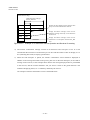
Contents
1
Introduction··········································································································································· 5-1
1.1
Foreword······································································································································· 5-1
1.2
Purpose ········································································································································· 5-1
1.3
Scope ············································································································································ 5-1
2
Applicable Documents ·························································································································· 5-2
3
Terminology and Abbreviations············································································································· 5-2
4
Required Specifications of Receiver······································································································ 5-4
4.1
Receiver Structure ························································································································· 5-4
4.2
User Interface································································································································ 5-6
4.3
Memory········································································································································· 5-7
4.4
Power Saving ································································································································ 5-8
4.5
Power-on Control ·························································································································· 5-8
4.5.1
Function Overview··················································································································· 5-8
4.5.2
Related Standards ····················································································································· 5-9
4.6
Power-on Call-in Control ·············································································································· 5-9
4.6.1
Function Overview··················································································································· 5-9
4.6.2
Related Standards ··················································································································· 5-10
4.7
Operation Priority during Standby······························································································· 5-10
4.8
Viewing Control for Free and Pay Programs with Content Protection ········································· 5-10
4.8.1
Viewing Processing ················································································································ 5-10
4.8.2
Related Standards ····················································································································5-11
4.9
Pay Program Reservation ·············································································································5-11
4.9.1
Function Overview··················································································································5-11
4.9.2
Cancellation of Reserved Program ························································································· 5-12
4.9.3
Related Standards ··················································································································· 5-12
4.10
PPV Viewing Processing ············································································································· 5-12
4.10.1 Function Overview················································································································· 5-12
4.10.2 Related Standards ··················································································································· 5-13
4.10.3 Control of PPV Monthly Purchase Limit ················································································ 5-13
4.10.4 Control of PPV Program Purchase Limit ················································································ 5-13
4.10.5 PPV Purchase Record and Its Display ···················································································· 5-14
4.10.6 Charges Based on Component································································································ 5-14
4.11
Copy Control on Pay Broadcasting······························································································ 5-15
―i―
ARIB TR-B15
Version 4.1-E1
4.11.1 Recording Control Information ·······························································································5-15
4.11.2 Copy Control on Flat/Tier Contracts ·······················································································5-15
4.11.3 Copy Control on PPV··············································································································5-16
4.11.4 Copy Control on Recordable PPV ···························································································5-16
4.12
Transmission of Viewing-History Information ·············································································5-21
4.12.1 Function Overview··················································································································5-21
4.12.2 Retry Over Notification Function ····························································································5-21
4.12.3 User Call-in Request Function·································································································5-21
4.12.4 Notification Function of Viewing-History Information Upload Date and Time ·······················5-21
4.12.5 Related Standards····················································································································5-22
4.13
Automatic Message Display·········································································································5-22
4.13.1 Basic Operation·······················································································································5-22
4.13.2 Related Standards····················································································································5-25
4.13.3 Display····································································································································5-25
4.13.4 Automatic Message Display for Receiver with Storage Function When Replaying Stored
Programs ·································································································································5-26
4.14
Mail Display ································································································································5-27
4.14.1 Basic Operation·······················································································································5-27
4.14.2 Related Standards····················································································································5-29
4.14.3 Message ID Processing ···········································································································5-29
4.15
Parental Control (Viewer Age Restriction) ···················································································5-31
4.15.1 Function Overview··················································································································5-31
4.15.2 Parental Level (Minimum Age for Viewing) ···········································································5-32
4.15.3 Password (PIN Number) ·········································································································5-32
4.15.4 Non-Restricted Condition········································································································5-32
4.15.5 Information Display of Viewing-Restricted Program·······························································5-32
4.15.6 Related Standards····················································································································5-33
4.16
Valid/Invalid/Non-usable IC Card ································································································5-33
4.17
Display of IC Card Information····································································································5-33
4.17.1 Function Overview··················································································································5-33
4.17.2 Related Standards····················································································································5-34
4.18
Error Notification Screen ·············································································································5-34
4.18.1 Function Overview··················································································································5-34
4.18.2 Related Standards····················································································································5-39
4.19
Operation When Valid IC Card Is Not Inserted·············································································5-39
―ii―
ARIB TR-B15
Version 4.1-E1
4.19.1 Error Message Display When Valid IC Card Is Not Inserted ·················································· 5-39
4.19.2 Pre-Registered Phase Conditions When IC Card Is Not Inserted on Sender Side···················· 5-40
4.19.3 Others····································································································································· 5-40
4.20
System Test ································································································································· 5-40
4.20.1 IC Card Test ··························································································································· 5-40
4.20.2 Connection Test······················································································································ 5-40
4.21
IRD Data Transmission ··············································································································· 5-40
4.22
CA Alternative Service················································································································ 5-41
4.22.1 Function Overview················································································································· 5-41
4.22.2 Basic Operation······················································································································ 5-41
4.22.3 Related Standards ··················································································································· 5-47
4.23
Caption/Superimposed-characters Scrambling and Display Priority············································ 5-47
4.23.1 Caption··································································································································· 5-47
4.23.2 Superimposed characters ········································································································ 5-47
4.24
Valid Conditional Access System (Consistency Check of CA_system_id of IC Card and
Broadcast Wave) ························································································································· 5-47
5
Operational Information ······················································································································ 5-49
5.1
Conditional Access Broadcasting ································································································ 5-49
5.2
Charge Unit (Chargeable ES) ······································································································ 5-49
5.3
Non-Scramble/Scramble·············································································································· 5-49
5.3.1
Overview································································································································ 5-49
5.3.2
Operation of Caption and Superimposed characters ······························································· 5-49
5.4
Free Program/Pay Program ········································································································· 5-50
5.4.1
Definitions of Free Program/Pay Program·············································································· 5-50
5.4.2
Operation ······························································································································· 5-50
5.4.3
Free Program with Content Protection···················································································· 5-51
5.4.4
Possible Combination of Pay, Free, Scramble, and Non-Scramble Programs ························· 5-52
5.5
Parental Rate Settings·················································································································· 5-54
5.6
Conditional Access System Descriptor ························································································ 5-55
5.6.1
Function ································································································································· 5-55
5.6.2
Data Structure························································································································· 5-55
5.6.3
Operation ······························································································································· 5-56
5.7
CAT Transmission ······················································································································· 5-57
5.7.1
Transmitted TS PID················································································································ 5-57
5.7.2
Data Structure························································································································· 5-57
―iii―
ARIB TR-B15
Version 4.1-E1
5.7.3
Transmitted Descriptor and Its Structure ·················································································5-57
5.7.4
Transmission Frequency··········································································································5-58
5.7.5
Update Frequency ···················································································································5-58
5.8
ECM ············································································································································5-58
5.8.1
ECM Identification··················································································································5-58
5.8.2
ECM Data Structure ················································································································5-58
5.8.3
ECM Application ····················································································································5-58
5.8.4
ECM Application Change········································································································5-59
5.8.5
ECM Update/Retransmission ··································································································5-60
5.8.6
Others······································································································································5-62
5.9
EMM············································································································································5-63
5.9.1
EMM Transmission Specifications··························································································5-63
5.9.2
EMM Message Transmission Specifications ···········································································5-63
5.9.3
EMM Transmission Frequency································································································5-64
5.9.4
EMM Transmission Order·······································································································5-65
5.10
Message Code for EMM Message································································································5-65
5.10.1 Format Number ·······················································································································5-65
5.10.2 Message Code Main Body Format of EMM Common Message for Format Number 0X01·····5-66
5.10.3 Differential Information Format of EMM Individual Message for Differential Format
Number 0X01··························································································································5-66
5.10.4 Example of Differential Information Use ················································································5-66
5.10.5 Character Code························································································································5-67
5.10.6 Recommended Display Position of Automatic Display Message·············································5-67
5.11
CA Contract Information Descriptor ····························································································5-69
5.12
Message ID ··································································································································5-69
5.12.1 Operation ································································································································5-69
5.12.2 Example of Send Operation·····································································································5-69
5.13
Recording Control Response of IC Card ······················································································5-71
5.14
CA Alternative Service·················································································································5-72
5.14.1 Operation Unit ························································································································5-72
5.14.2 Link Service ····························································································································5-72
5.14.3 Transmission Operation of Link Descriptor·············································································5-72
5.15
CA Service Descriptor··················································································································5-73
5.15.1 Operation ································································································································5-73
5.15.2 Delay Time Operation ·············································································································5-73
―iv―
ARIB TR-B15
Version 4.1-E1
A
Commentary (Supplementary Explanation of This Volume) ································································ 5-74
A-1
EMM Reception and Update ······································································································· 5-74
A-2
History of EMM Message Format Creation················································································· 5-74
A-3
Retransmission Cycle and Update Cycle of ECM ······································································· 5-75
A-3-1 Retransmission Cycle ············································································································· 5-75
A-3-2 Update Cycle·························································································································· 5-75
A-4
Recordable PPV Purchase and Copy Protection ·········································································· 5-76
A-5
Special TS ··································································································································· 5-77
A-5-1 Overview································································································································ 5-77
A-5-2 Special TS ······························································································································ 5-77
A-6
Basic Concept of Mandatory and Optional ·················································································· 5-78
A-7
Card ID Display ·························································································································· 5-80
A-8
Specifications of Conditional Access System for Digital Satellite Broadcasting·························· 5-80
A-8-1 Operation of Multiple Conditional Access Systems ································································ 5-80
A-8-2 Concept of Compliance with Part 1 of STD-B25 (Assumption) ············································· 5-81
B
Appendix············································································································································· 5-85
B-1
Number Assignment Management of CA Alternative Message Number······································ 5-85
B-2
Contact for Inquiries regarding IC Card ······················································································ 5-85
―v―
ARIB TR-B15
Version 4.1-E1
(This page is intentionally left Blank.)
―vi―
ARIB TR-B15
Version 4.1-E1
1
Introduction
1.1 Foreword
The Specifications regarding the conditional access system for digital satellite broadcast receiver are stipulated
in Part 1 of the Reception Control System (Conditional Access System), “Access Control Method on Digital
Broadcasting” (ARIB STD-B25 Part 1).
In this volume, the required specifications for receivers and their operational specifications are stipulated based
on Part 1 of the ARIB STD-B25 to complement it. Thus, please refer to Part 1 of the ARIB STD-B25 for the
items that are not mentioned in this volume.
1.2 Purpose
This volume describes, based on Part 1 of the ARIB STD-B25, the required specifications for receivers and the
operational information that should be considered when installing the CAS functions in digital satellite
broadcasting receivers.
1.3 Scope
This specification document applies to the receiver specifications and the transmission operation provisions for
the Conditional Access System (CAS) method which complies with Part 1 of the ARIB STD-B25.
―5-1―
ARIB TR-B15
Version 4.1-E1
2
Applicable Documents
(1) Telecommunications Technology Council Advisory Report No.17
(2) Telecommunications Technology Council Advisory Report No.74
(3) Ministry of Internal Affairs and Communications Ordinance No. 26, 2003
(4) Ministry of Internal Affairs and Communications Notification No. 36, 2003
(5) Ministry of Internal Affairs and Communications Notification No. 37, 2003
(6) Ministry of Internal Affairs and Communications Notification No. 40, 2003
(7) ARIB STD-B10 “Service Information for Digital Broadcasting System”
(8) ARIB STD-B20 “Transmission System for Digital Satellite Broadcasting”
(9) ARIB STD-B21 “Receiver for Digital Broadcasting”
(10) ARIB STD-B25 “Conditional Access System Specifications for Digital Broadcasting” Part 1
(11) ARIB STD-B24 “Data Coding and Transmission Specification for Digital Broadcasting”
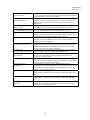
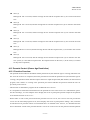
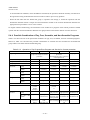
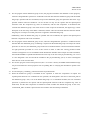
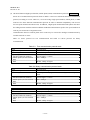
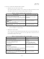
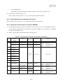
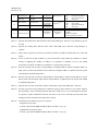
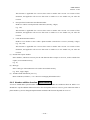
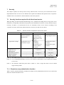
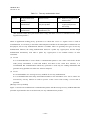
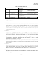
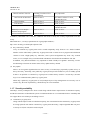
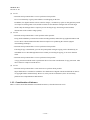
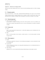
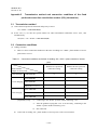
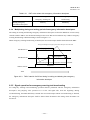
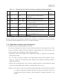
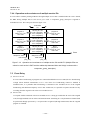
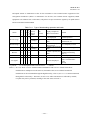
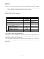
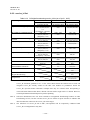
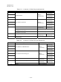
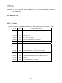
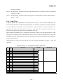
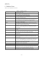
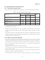
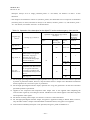
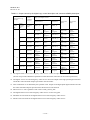
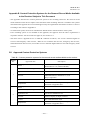
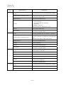
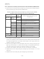
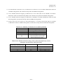
3
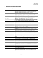
Terminology and Abbreviations
Table 3-1
ARIB
(Association of Radio
Industries and Business)
CA
(Conditional Access) system
CAT
(Conditional Access Table)
Component
Descriptor
ECM
(Entitlement Control
Message)
EIT
(Event Information Table)
EMM
(Entitlement Management
Message)
ES
(Elementary Stream)
Event
Explanation of Terminology and Abbreviations
Association of Radio Industries and Business.
Broadcasters, telecommunication companies, and manufacturers
participate in this organization. It standardizes the technology
related to domestic use of radio wave.
Conditional Access System.
This system controls viewing of services (arranged channels) and
events (programs).
From the relevant information that constitutes the conditional
access broadcasting, CAT specifies the packet identifier of the TS
packet that transmits individual information.
Component such as video, audio, text, and various data, etc.
It is the element that constitutes an event (programs).
Descriptor is a description area arranged in the table to carry a
variety of information.
ECM is common information which consists of program
information (information related to program and keys for
descrambling, etc.) and control information (forced on/off
command of scrambling function in the decoder)
Event information table holds the information related to the
program, such as the program name, the broadcasting date and
time, and the program contents.
EMM is individual information that contains work keys to decode
secret codes of each subscriber’s contract information and common
information.
Elementary stream corresponds to encoded video, audio, and
independent data in PES packets. A single ES is transmitted by the
PES packet that has the same stream ID.
Event is a collection of streams in predefined starting/ending time
within the same service (arranged channel), such as news and
dramas.
―5-2―
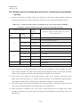
ARIB TR-B15
Version 4.1-E1
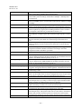
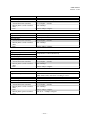
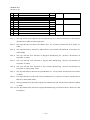
PID
(Packet Identifier)
PMT
(Program Map Table)
PPV
(Pay Per View)
SDT
(Service Description Table)
Automatic Display Message
Mail
Parental Control
(Viewer Age Restriction)
Parental Level
(Minimum Age for Viewing)
Password
(PIN Number)
CA Alternative Service
Conditional Access
Broadcasting
Pay Program
Free Program
Free Program with Content
Protection
Packet ID (identifier).
It is a 13-bit stream identifying information which shows individual
stream attribution of the relevant packet.
PMT specifies the packet ID of TS packet that transmits encoding
signals to compose programs and the packet ID of TS packet that
transmits the common information from pay-program-related
information.
Pay per view is pay broadcasting. Fees are charged for each
program or for program groups based on the viewing mode.
Service description table holds the information related to arranged
channels, such as channel names and broadcasters’ names.
Among the EMM messages sent to each IC card, the message
stored in the IC card is defined as automatic display message, and it
is simultaneously displayed during program reception.
Among the EMM messages sent to each IC card, the message
stored in a receiver is defined as mail, and it can be arbitrarily
called up by the user operation.
Parental control is a system to restrict program viewing using the
combination of parental rate (age restriction rate) listed as program
attribution and parental level (minimum age for viewing) in the
receiver set by the user, using a password.
Parental level is the information of the minimum age for viewing
that is set in the receiver to achieve parental control.
Password is a confirmation code used for parental control (viewer
age restriction) and PPV program purchase limit function. It
consists of a 4-digit number.
CA alternative service is a service that broadcaster provides to
direct their viewers to “Guide Channel” when they select scramble
channels that are not in their subscription.
Conditional access broadcasting is broadcasting that uses
conditional access method descriptor. In this broadcasting, there are
pay programs, broadcasting that uses EMM messages, and free
programs with content protection.
Pay program is a program whose default ES group is subject to
charge, and it is listed as free_CA_mode=1 in the SDT and in the
EIT.
Free program is a program whose default ES group is not subject to
charge, and it is listed as free_CA_mode=0 in the SDT and in the
EIT.
Free program with content protection is a free program sent
securely by broadcasting wave without customer control for the
purpose of content right protection.
―5-3―
ARIB TR-B15
Version 4.1-E1
4
Required Specifications of Receiver
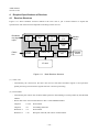
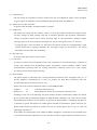
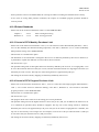
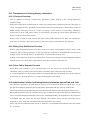
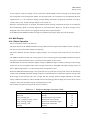
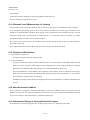
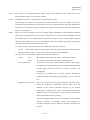
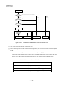
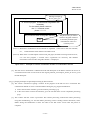
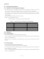
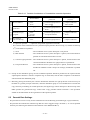
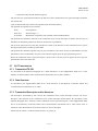
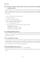
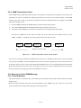
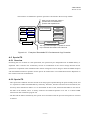
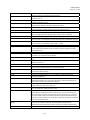
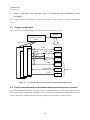
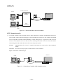
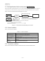
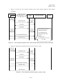
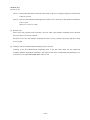
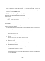
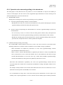
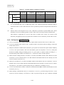
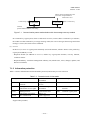
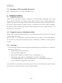
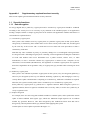
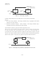
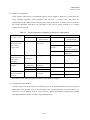
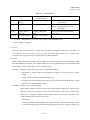
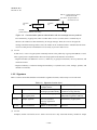
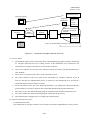
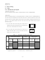
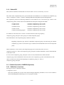
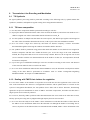
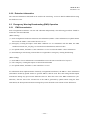
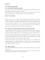
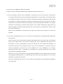
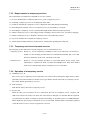
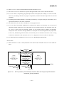
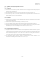
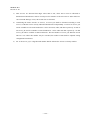
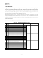
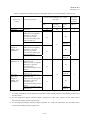
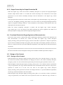
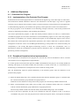
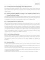
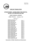
4.1 Receiver Structure
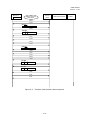
Figure 4.1-1 shows hardware structure related to the CAS. This is just a model structure to explain the
specifications. The actual structure depends on the design of the receiver.
Broadcas
ting signal
input
Tuner
unit
Descrambler
TS decode
unit
Decode unit
for video and
audio
Monitor
output
Display
unit
Public
line
Phone
modem
Control unit
Key input
unit
Remote
control
IC card
Figure 4.1-1
Basic Receiver Structure
(1) Tuner Unit
- Controlled by the control unit, the tuner unit receives and selects broadcast signals. It also performs
packet processing of transmission signals and error correction processing.
(2) Descrambler
- Controlled by the control unit, the descrambler performs descrambling of certain packets by the MULTI2
method.
- Please refer to the sections listed below in Part 1 of the ARIB STD-B25.
Chapter 2
2.2.2.4
Descrambler
Chapter 4
4.8
Scrambling Detection
Reference 2
3.4
Descrambler
Reference 2
3.10
Reception of ECM, and control of Descrambler
―5-4―
ARIB TR-B15
Version 4.1-E1
(3) TS decode unit
- The TS decode unit separates necessary packets from the TS multiplexed signals, selects broadcast
program signals, and separates various multiplexed data (SI data, ECM, and EMM, etc.)
(4) Decode unit for video and audio
- It decodes video and audio, and outputs them to a monitor.
(5) Display unit
- The display unit equips the user interface, which is a screen presentation mechanism to display menus
and lists, settings for PPV purchase limit and its purchase operation, PPV purchase confirmation1),
settings for parental control and its unlock password input, IC card information, automatic display
messages, mail, IC card test, phone line connection test, and IC card response errors, etc. for users.
1)
Among the PPV service functions, the ones other than phone modem and setting/deleting of PIN
number should not be operated. Hereafter, this will apply to PPV service functions. The related
description can be found in the commentary.
(6) Key input unit
- It processes key inputs from a remote control.
(7) Control unit
- It controls an entire receiver. Especially in the CAS, it performs IC card communication, processing of
various data separated from broadcasting signals, descrambler control, telephone modem control
(communication processing with the viewing information collection center), time count, display
processing control, and key input processing.
(8) Phone modem
- The phone modem is connected to the viewing information collection center with public lines, etc., to
process telephone communications. It does not perform the IRD data transmission that uses
encryption/decryption processing of the IC card.
- Please refer to the sections listed below in Part 1 of the ARIB STD-B25.
Chapter 4
4.5
Communications Functions
Reference 2
3.6
Phone Modem or similar device, and basic communications
- Installing at least one of the following: the phone modem, the data communication adapter for cellular
phone, and the data communication adapter for PHS should be mandatory only if the receiver equips
data-broadcasting interactive service function. In general, the phone modem is installed as mandatory. It
is desirable to specify the adapters for cellular phone and PHS as manufacturer options. However, the
phone modem should be optional in mobile receivers for mobile objects such as cars or small and
lightweight portable TVs2).
- If the adapter for cellular phone or the adapter for PHS is equipped, it is preferable to also install the retry
over notification function mentioned in 4.12.2, and the user call-in request function mentioned in 4.12.3
―5-5―
ARIB TR-B15
Version 4.1-E1
in this volume.
2)
The portable TV is defined as a display-integrated receiver operated by DC power source (AC adapter,
etc.) with the monitor size not larger than 14 inches.
(9) IC card and low-speed CA interface
- The IC card and low-speed CA interface are mounted in a receiver, and they communicate with the
control unit of the receiver. As a core CAS processing of the receiver, they decode encrypted EMM as
they receive it, control contract data, decode encrypted ECM, process pay program viewing control,
process viewing-history information control, process transmission of viewing-history information to
broadcaster, decode encrypted EMM messages, etc.
- While issuing commands with preset transmission orders, such as the commands that require several
transmissions and receptions of commands/responses (ones with PDU numbers) and the call-in status due
to communication related commands, the receiver must not issue unnecessary commands for program
viewing except for the ECM reception command, the PPV status request command, the PPV program
purchase command, the contract confirmation command, and the card request command.
- Prepaid card will not be used for the receivers that comply with this document. Consequently, the
“Prepayment balance confirmation command” should not be issued. The standards related to prepaid card
will be revised at an appropriate time for the prepaid operation.
- The low-speed CA interface described in the following sections in Part 1 of the ARIB STD-B25 should
be installed.
Chapter 4
4.3
CA Interface
Reference 2
3.5
Communication control of IC card
- The contact for inquiries regarding IC card can be found in Appendix B-2.
(10) Remote control
- Although the buttons on remote control depend on product planning, it is assumed that numeric keypad
for password input, menu key for PPV purchase and settings, cursor control keys, enter keys are needed.
(11) Display on main body of receiver
- It is desirable to install LEDs, etc. in a receiver’s main body to notify the status of power-on control,
power-on call-in control, and telephone line use due to calling the center.
4.2 User Interface
- The details of user interface are left to product planning.
Hence, the display screen described in the [Procedure] of “Part 1, 4. Receiver Technical Specifications” in the
ARIB STD-B25 is an example for better understanding.
- Automatic display messages will be superimposed.
- The use of numeric keypad on the remote control is generally expected to input passwords, etc. However,
―5-6―
ARIB TR-B15
Version 4.1-E1
input using a graphic keyboard on the screen is acceptable, and this document does not define it particularly.
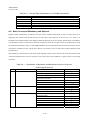
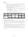
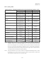
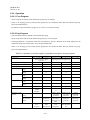
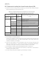
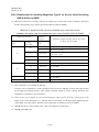
4.3 Memory
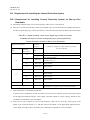
- The necessary NVRAM for conditional access services is as follow.
1)
It should be 8 KB or more for mail reception. This is the required size for storing 10 or more pieces of
mail with 800 bytes at most per mail.
2)
For recycling mail ID, it is necessary to store 7 message IDs and reception time per one broadcaster, and
it should be 32 or more broadcasters.
3)
For power-on control management or power-on call-in control for each broadcaster (32 records at most),
additional memory may be required depending on the receiver’s design as described in 3.12.2 Specific
Examples of Power-on Control in Reference 2 in Part 1 of the ARIB STD-B25. However, the size and the
installing means are arbitrarily defined by the receiver.
4)
As a manufacturer option function, purchase history should be stored in the NVRAM if 4.10.5 PPV
Purchase Record and Its Display in this volume is installed.
- The deletion function of personal information related to the conditional access and stored in the NVRAM
should be equipped from the prospective of protecting (preventing the leakage of) personal information used
in the CAS, in case of transferring or disposing the receiver.
- When password is set, it is desirable to erase (delete) the personal information related to the conditional
access after the password is input.
- The related description can be found in 4.13.10 Clear Function of Personal Information in Volume 2 in this
document.
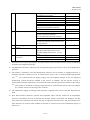
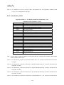
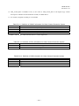
- Regarding the functions stipulated in this volume, the personal information that should be erased is as follow.
1)
PPV-related information
i.
PPV monthly purchase limit (See 4.10.3 in this volume)
ii.
Single PPV program purchase limit (See 4.10.4 in this volume)
iii.
PPV purchase record (See 4.10.5 in this volume)
2)
EMM Mail (See 4.14 in this volume)
3)
Parental control related information
i.
Parental level (See 4.15.2 in this volume)
ii.
Password (See 4.15.3 in this volume)
―5-7―
ARIB TR-B15
Version 4.1-E1
4.4 Power Saving
- In digital satellite broadcasting conditional access system, power-on control and power-on call-in control are
adopted in order to save power on viewing-history information call-in control for updating EMM or collecting
viewing information. For example, in the case of EMM power-on control, the relevant EMM is received while
receiving the subscribed service at the first time of subscription. After that, the subsequent EMM update
timing can be determined by the response of the IC card, making the power-saving design for the time gap
until the next EMM reception possible.
- In order to achieve the operation mentioned above, the receiver needs timer function (calendar function)
which counts absolute time. Please refer to the sections listed below for the detail.
ARIB STD-B25
Part 1
Reference 2
3.1
Power saving
Reference 2
3.2
Timer
4.5 Power-on Control
4.5.1 Function Overview
- This is a function to receive EMM from the specified network and transport stream at the specified time
during the power-on control period specified by the EMM, by turning on the circuit power at least for the
EMM reception when entering standby mode with sub-power off (not the AC off but the condition that the
power is turned off by a remote control).
- The power-on control is set for each broadcaster (32 records at most). If those power-on control periods
overlap, the reception control will be sequentially conducted for all broadcasters. In addition, even if the
power-on control is interrupted, the schedule management for all broadcasters will be evenly carried out in
order to avoid that the reception control concentrates into a certain broadcaster every time.
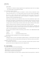
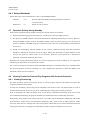
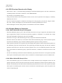
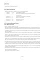
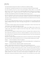
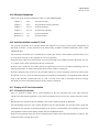
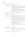
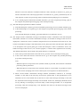
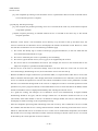
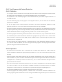
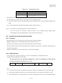
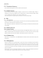
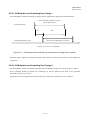
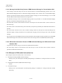
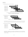
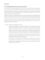
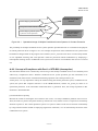
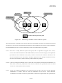
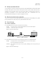
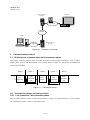
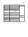
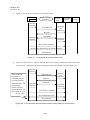
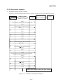
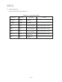
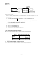
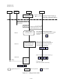
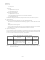
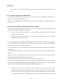
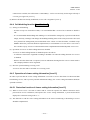
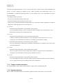
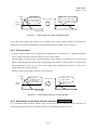
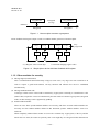
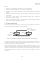
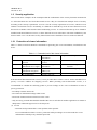
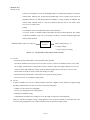
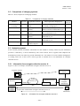
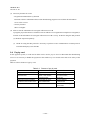
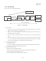
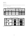
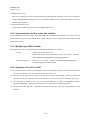
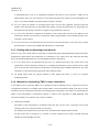
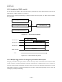
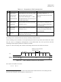
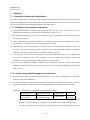
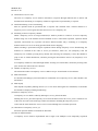
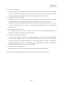
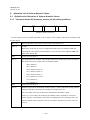
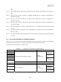
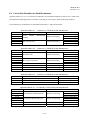
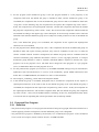
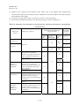
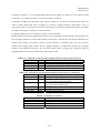
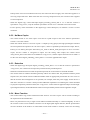
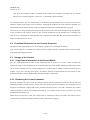
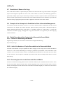
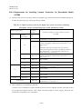
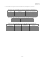
- When the EMM reception is instructed by the CA EMM TS descriptors listed in NIT during the power-on
period for EMM reception specified by the power-on control information request command/response, the
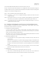
EMM reception instruction by the NIT has priority as shown in the figure below. Please refer to the section,
4.7 Operation Priority during Standby, in this volume for the other operations during standby and their
priorities.
―5-8―
ARIB TR-B15
Version 4.1-E1
The power-on control period by IC card response
The period with the description of
CA_emm_ts_descriptor in NIT
A
B
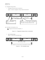
Figure 4.5-1
C
EMM Reception Priority during Power-on Control Period
TS1 is defined as the reception TS_id by power-on control, and L1 is defined as the power-on retention time.
TS2 is defined as the reception TS_id by CA_emm_ts_descriptor, and L2 is defined as the power-on retention
time.
In the figure shown above, the operations to obtain EMM for each A, B, and C period during standby are as
follow.
Period A:
The reception TS=TS1 retains the power supply for L1.
Period B:
After the reception TS=TS2 retains the power supply for L2, the reception TS=TS1
continuously retains the power supply for L1.
Period C:
The reception TS=TS1 retains the power supply for L1.
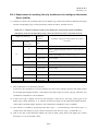
4.5.2 Related Standards
- Please refer to the sections listed below in Part 1 of the ARIB STD-B25.
Reference 1
4
Power-on control
Reference 2
3.12
Power-on control
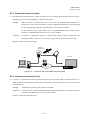
4.6 Power-on Call-in Control
4.6.1 Function Overview
- When a call-in date is obtained from the IC card for PPV viewing-history collection, the receiver accepts a
call-in request from the IC card on the call-in date, and it communicates with the viewing-history information
collection center. If the receiver is in standby mode with sub-power off, it turns on enough power for the
necessary circuit to communicate with the viewing-history information collection center, in addition to the IC
card.
―5-9―
ARIB TR-B15
Version 4.1-E1
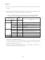
4.6.2 Related Standards
- Please refer to the sections listed below in Part 1 of the ARIB STD-B25.
Chapter 4
4.5.1
Receiver Operation During Viewing Information Collection
Communications
Reference 2
3.8
Power-on call-in control
4.7 Operation Priority during Standby
- When various operations during standby overlap, their priority orders are as follows.
1)
Reserved operations (program reservation, etc.) made by users have the highest priority.
2)
The priority of EMM reception control and download is arbitrarily defined by the receiver. However,
among the EMM reception controls, the EMM reception control by NIT has priority over the power-on
control. In addition, the EMM reception control has priority in the case of downloading common data for
all receivers.
3)
Except for downloading software updates for the receiver, parallel processing with other operations
should be conducted in the power-on call-in control. During the download of software updates for the
receiver, the power-on call-in control is not necessary. Therefore, which operation or download is
processed is arbitrarily defined by the receiver.
- Especially for acquiring download contents, if a reserved operation (reserved recording, etc.) is expected to
start during the acquisition, do not obtain the contents.
- If it is time for the power-on period to obtain the EMM acquisition or if download delivery is scheduled when
the reserved operation (reserved recordings, etc.) has completed, the operation to obtain the EMM or the
download contents will be carried out.
4.8 Viewing Control for Free and Pay Programs with Content Protection
4.8.1 Viewing Processing
- The basic operation selects the transport stream of chosen program based on the PSI/SI and selects the
components that form the program.
- It refers the scrambling control flag and the adaptation field control of the TS packet header as well as
provides the ECM to the IC card as it receives, conducting the viewing control with the responses.
- Even if components are subject to charges, they are not always scrambled broadcasting. In the case of such
non-scrambled broadcasting, the program should be provided based on the scramble flag assessment.
- Recognizing “Free program with content protection” is possible with the broadcaster identifying value of the
ECM. However, in the receiver, the broadcaster identifying value, which is also for right protection, makes
sense only when the error message due to the card response without Kw (See 4.18 Error Notification Screen)
is displayed. Therefore, everything else should be processed as normal conditional access service.
―5-10―
ARIB TR-B15
Version 4.1-E1
4.8.2 Related Standards
- Please refer to the sections listed below in Part 1 of the ARIB STD-B25.
Chapter 4
4.2.3
Program Viewing
Chapter 4
4.8
Scrambling Detection
Reference 2
3.5
Communication control of IC card
Reference 2
3.10
Reception of ECM and control of Descrambler
Reference 2
3.15
Program viewing
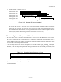
5
Operational Information
- This volume
4.9 Pay Program Reservation
4.9.1 Function Overview
- Program reservation should be treated without any distinction between free and pay broadcasting. It is
preferable that the program reservation function includes pay program in its range when receivers are
equipped with the function.
- Whether the reserved program is available for viewing is determined by the CA contract information
descriptor from the SDT or the EIT, and the viewing availability, the recording restriction information, and the
viewing mode based on the contract confirmation command/response are obtained in the IC card. The
viewing mode can be determined by the return code. When this viewing mode is PPV mode, the PPV viewing
fee 1, the recordable PPV viewing fee 2, and the deadline of reserved purchase are included in the response
from the IC card. The deadline of reserved purchase means that PPV purchase command will not be accepted
after the deadline time, and more specifically, the offset time from the beginning of the program is listed. For
example, if the program is not available for viewing due to raining, etc. at the program’s starting time, it can
be discovered at the time of setting the reservation that the program cannot be purchased since the deadline of
reserved purchase passes after the program starts.
- On program reservation, when the CA contract information descriptor does not exist in SDT and EIT and
free_CA_mode is 0, it is considered that the reservation can be made without any condition. (Free program)
However, even in this case, IC card insertion is also required when the program is received because the
program may be a free program with content protection. Therefore, displaying the messages to advise valid IC
card insertion at the time of free program reservation is desirable when IC card is not inserted or the IC card is
not valid.
- When the CA contract information descriptor does not exist and free_CA_mode is 1, the reservation cannot be
made.
- The CA contract information descriptors define the contract confirmation information of the entire service in
the SDT, and they define that of each program in the EIT. When these descriptors are defined in both the SDT
and the EIT, the definition in the EIT has priority.
―5-11―
ARIB TR-B15
Version 4.1-E1
4.9.2 Cancellation of Reserved Program
- Once a program is reserved, it can be still cancelled if the program has not started yet (before issuing the PPV
purchase command), but it cannot be cancelled after the purchase.
- If, for some reasons, the reserved program does not start playing even after the deadline of reserved purchase,
the reservation can be automatically cancelled.
- It is desirable to install the means to provide the history of user’s operations and the automatic cancellation
mentioned above by the user operation when the reserved program is cancelled.
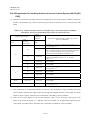
4.9.3 Related Standards
- Please refer to the sections listed below in Part 1 of the ARIB STD-B25.
Chapter 4
4.2.4
Program Reservations (Optional)
Reference 2
3.16
Program reservation
4.10 PPV Viewing Processing
4.10.1 Function Overview
- When the IC card instructs other than the preview period or the preview is terminated to switch to the
program purchase by the user operation, etc., the user interface for purchasing will be displayed. At this time,
it is desirable to show clearly the viewing fee obtained by the CA contract information descriptors listed in the
EIT or the SDT, the PPV status request command from the IC card, and the PPV viewing fee obtained by the
contract confirmation command.
- When the program is not recordable at the time of purchase, a message to explain should be displayed and
processed with copy control.
- When the program is recordable only by the purchaser at the time of purchase, please refer to 4.11. Copy
Control for Pay Broadcasting in this volume.
- When the receiver equips functions such as the PPV monthly purchase limit and the single program purchase
limit, the predetermined operation should be performed at the time of PPV purchase.
- Even if the video components whose service type is not digital do not exist, the PPV with program-based
charge can be operated. The PPV mentioned here means an operational form with charge, despite of its
service type.
- When program viewing is interrupted during the preview status by the menu or the parental control, etc., the
IC card recognizes it as the middle of the preview status if the ECM is being sent continuously to the IC card.
Thus, this should be considered at the time of designing.
- The viewing fee and the recording fee can be obtained by the PPV status request and the contract
confirmation commands/responses. The recording fee mentioned here means the viewing fee that includes the
fee for recording in the case of purchasing a recordable program.
―5-12―
ARIB TR-B15
Version 4.1-E1
- On the purchase screen of recordable PPV, the viewing fee and the recording fee should be shown clearly.
- At the time of issuing PPV purchase command, the request of recordable program purchase should be
correctly issued.
4.10.2 Related Standards
- Please refer to the sections listed below in Part 1 of the ARIB STD-B25.
Chapter 4
4.2.3.3
PPV Viewing Processing
Reference 2
3.15.6
PPV viewing processes
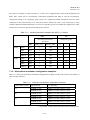
4.10.3 Control of PPV Monthly Purchase Limit
- Please refer to the functions mentioned in “Part 1, 2.2.2.20 Control of Limit PPV Monthly Purchase,” “Part 1,
4.2.11.4 PPV Monthly fee allowance Setting (Optional),” and “Part 1, Reference 2, 3.21 Control of Monthly
PPV purchase ceiling” in the ARIB STD-B25.
- This function is a manufacturer option.
- The definition of one month that is managed in the receiver is arbitrarily defined by the receiver. However, it
is preferable to explain the definition of one month in the user manual.
- The unit of fees is yen.
- The possible setting limit of the highest amount is arbitrarily defined by the receiver. As a rough guide, it can
be set to the minimum amount of 500 yen or more, and the maximum amount of 5-digit figure and more (ten
thousand yen scale or more). The step size of the setting amount is approximately 500 yen.
- The settings at the time of factory shipping are arbitrarily defined by the receiver.
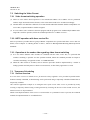
4.10.4 Control of PPV Program Purchase Limit
- Please refer to the functions mentioned in “Part 1, 2.2.2.21 Control to Limit Single program PPV Purchase,”
“Part 1, 4.2.11.3 PPV Unit Fee Allowance Setting,” and “Part 1, Reference 2, 3.22 Control to limit PPV
program purchase” in the ARIB STD-B25.
- This function is a manufacturer option.
- The unit of fees is yen.
- The program which is the same fee as the setting price can be purchased.
- The possible setting limit of the highest amount is from 100 yen to 1,000 yen. In addition, the function to set
it as unlimited (no purchase limit) should be equipped. The step size of the setting amount is arbitrarily
defined by the receiver, but approximately 100 yen to 500 yen can be used as rough guide for it. Besides, this
step size is not necessary to be a single size. For example, it can be set as 100 yen when the limit is 1,000 yen
or less and as 500 yen when the limit is 1,000 yen or more.
- The settings at the time of factory shipping are arbitrarily defined by the receiver.
―5-13―
ARIB TR-B15
Version 4.1-E1
4.10.5 PPV Purchase Record and Its Display
- Please refer to “Part 1, 2.2.2.22 Recording and Display of Purchased PPV Programs” and “Part 1, Reference 2,
3.20 PPV purchase record and its indication” in the ARIB STD-B25.
- This function is a manufacturer option.
- Listing the total amount of fee and purchase amount on the screen of purchase record display is arbitrarily
defined by the receiver.
- The time of purchase program is defined as the stating time of the program (year (the last 2 digits)/ month /
day / hour / minute). The displays of year and minute are arbitrarily defined by the receiver.
- When installing this function, PPV purchase record should be stored in the NVRAM.
4.10.6 Charges Based on Component
4.10.6.1 When Default ES Group Is Chargeable
- When the default ES group (a pair of video and audio ES if the service type is digital TV, and audio ES if the
type is digital audio) except for the data ES, separately regulated, is chargeable, it is operated with a single
ECM. The ECM_PID is defined in the first loop of the PMT.
- When the service type is data broadcasting, the entry component should be the default ES.
- When the video ES, the audio ES, or the data ES other than the default ES group is selected and the separate
ECM from the default ES group is defined, additional purchase operation will be performed.
- In PPV purchase operation, do not perform any other ES purchase operation without the purchase operation of
the default ES group that excludes data ES. After purchasing the default ES group, the other ES should be
purchased. Note that the IC card does not indicate purchase error even if an additional purchase of the other
ES is entered before the default ES group is purchased. Therefore, it should be considered at the time of the
settings.
- The PPV fee defined by the ES other than the default ES group obtained from the IC card responses (the PPV
status request command/response and the contract confirmation command/response) means an additional fee.
4.10.6.2 When Default ES Group Is Free
- Even if the default ES group is free, the other ES (for example, data ES) may be chargeable. In this case, the
purchase operation of the ES will be executed if the ES with valid ECM is selected. Since the default is free,
the PPV fee defined by the ES other than the default ES group obtained from the IC card responses (the PPV
status request command/response and the contract confirmation command/response) means the purchase fee
for the corresponding ES.
―5-14―
ARIB TR-B15
Version 4.1-E1
4.11 Copy Control on Pay Broadcasting
4.11.1 Recording Control Information
- Please refer to Volume 2 and Volume 8 for the copy control method.
- Please refer to Volume 4 and Volume 8 for the copy control information on PSI/SI.
- Please refer to Part 1 of the ARIB STD-B25 for the IC card response.
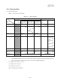
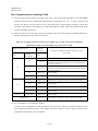
- The recording control information obtained by the IC card response is as follow.
The commands that provide the recording control information are the “PPV status request
command/response,” the “contract confirmation command/response,” and the “ECM reception
command/response.” This section classifies the PPV program with recordable purchase operation and the
response status of the IC card.
A) Before purchase operation
1)
Non-recordable:
Program attribute that indicates the recording is prohibited
2)
Recordable:
Program attribute that indicates the recording is permitted
3)
Recordable only by the purchaser: Program attribute status before the user purchase
B) After purchase operation
1)
Non-recordable:
Result of the charged fee when the user did not perform
purchase operation of recordable program
2)
Recordable:
Result of the charged fee when the user purchased recordable
program
3)
Recordable only by the purchaser: After executing the purchase operation, this status does not
return in the ECM reception command and the contract
confirmation command/response.
4.11.2 Copy Control on Flat/Tier Contracts
- No recordable program purchase is operated for flat/tier contracts. Therefore, the record control information
obtained by the IC card response is either recordable or non-recordable.
- When the program to be viewed or reserved by the response of the IC card is under the flat/tier contracts and
the PPV is not for recordable purchase, the recording control information from the IC card will be ignored,
and the control information listed on the digital copy control descriptor and the content availability descriptor
will be followed.
―5-15―
ARIB TR-B15
Version 4.1-E1
4.11.3 Copy Control on PPV
- The commands/responses from the IC card before PPV purchase are the responses for the program attributes.
On the other hand, the “contract confirmation command/response” and the “ECM reception
command/response” after PPV purchase are the response for the fee results. These are different from the
“PPV status request command/response,” which still returns program attributes after PPV purchase. This
should be considered when the receivers are designed.
- When a purchased PPV program is switched to another channel and switched back to the purchased PPV
program again, the corresponding copy control by the recording information of the “ECM reception
command/response,” the digital copy control descriptor, and the content availability descriptor should be
performed.
- The message which indicates that the program is not recordable should be displayed on the purchase screen if
copying the program is prohibited.
- Except for recordable PPV, the control information listed on the digital copy control descriptor and the
content availability descriptor has priority over the recording information from the IC card. See 4.11.4 Copy
Control for Recordable PPV in this volume for the operational specifications for recordable PPV.
- During the period in which preview is allowed by the IC card response, the macrovision control of video
output of the receiver should be off, and the control of CGMS-A, IEC60958, and DTCP method is managed
by the values listed on the digital copy control descriptor and the content availability descriptor.
4.11.4 Copy Control on Recordable PPV
4.11.4.1 Basic Concept
- The choices of purchase with recording or purchase for view only without recording should be available for
the recordable PPV purchase operated by the description of the digital copy control descriptor and the IC card
response.
- At the purchase of recordable programs, the recording control operation for the recordable purchase is
different from that for the view-only purchase.
- For the PPV program operated by the PPV status request command/response, the contract confirmation
command/response, and the ECM reception command/response, the basic receiver operations corresponding
to the purchase result are as follow.
1)
When a program was purchased with recording
- The digital_recording_control_data of the digital copy control descriptor should be kept and processed
with “10”.
- After the purchase is complete, the macrovision control of the analog video output of the receiver
should be off.
- The parameters of the output to CGMS-A or high-speed digital interface use the descriptions on the
―5-16―
ARIB TR-B15
Version 4.1-E1
digital copy control descriptor and the content availability descriptor as they are.
2)
When a program was purchased for view only
- The digital_recording_control_data of the digital copy control descriptor should be rewritten to “11”
and then, processed.
- When a program was purchased for view only, the digital_recording_control_data is processed with
“11” following the process mentioned above, and the APS_control_data is processed with other than 00.
More specifically, the macrovision control of the analog video output of the receiver should be on.
- For the parameters of the output to CGMS-A or high-speed digital interface, the
digital_recording_control_data will be rewritten to “11”, and the APS_control_data uses the
descriptions on the digital copy control descriptor as they are.
- When a program is purchased for view only, it is the same as the “copy-prohibited” content. As a result,
it can be stored temporally until the time regulated in “temporally-storage allowed time” listed on the
content availability descriptor. See Volume 8 for the detail.
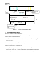
4.11.4.2 Transmission Rules and Receiver Processing for Recordable PPV
(1) When Default ES Group Is Chargeable
i.
Operational rules of transmission
- The valid ECM is listed on the first loop of the PMT, and the operation of recordable program
purchase will be carried out. In the PPV mentioned here, which the recordable purchase operation is
performed for, the IC card response before the program purchase is “Recordable only by the
purchaser.”
- Digital copy control descriptor is listed on the first loop of the PMT. The
digital_recording_control_data must be operated with “10”, and the APS_control_data is also always
operated with values other than “00”. Nevertheless, if the service type is digital audio (including
temporary) or data broadcasting (including temporary) with copy_control_type=11, it can be
operated with digital_recording_control_data=10 and APS=00. This is intended for the audio
programs with copy control on the audio. Therefore, the macrovision control does not work for the
video ES, which is additional data. When applying the macrovision control to the video ES in these
service types, it must be operated only with digital_recording_control_data=10 and APS≠00.
- In the second loop of the PMT, the digital copy control descriptor can be listed individually for the
ES of 0x40-0x7F component tag. When the default ES is chargeable and is for recordable PPV
purchase operation, the digital_recording_control_data listed on the digital copy control descriptor
included in the second loop is operated with “10” or “00”.
- In the operation of recordable PPV, when the ES of 0x00-0x3F component tag excluding the default
ES group is charged for each ES by separate ECM, the operation of recordable program purchase is
―5-17―
ARIB TR-B15
Version 4.1-E1
not performed for the ECM listed on the second loop of the PMT, and it is operated with
“Recordable.” As it is mentioned later, the receiver is to perform the copy control of the ES whose
component tag is between 0x00 and 0x3F based on the result of the purchase mode of the default ES
group (in other words, whether it was purchase with recording or it was purchase with view only)
for the purchase operation of either recordable or view only of the main program.
- For the data ES of 0x40-0x7F component tag, the digital copy control descriptor can be listed for
each ES in the second loop of the PMT. When the ES is charged by the separate ECM from the
default ES group, the recordable purchase for each ES can be operated. In other words, the operation
by the IC card response of “Recordable only by the purchaser” can be performed. However, the
recording control of this data ES is reflected only in the control of IEEE1394. For the partial TS
output from IEEE1394 output, the EMI is set by the most strict copy control value in the TS. As a
consequence, when a viewer purchases certain ES with view-only option, even the main program
cannot be recorded if the receiver outputs the partial TS only on a program-by-program basis. Thus,
the transmission should be operated in accordance with this point.
ii.
Receiver processing
- After choosing a program, when the PPV purchase is operated for the default ES group, the PPV
purchase operation of recordable purchase should be conducted based on the content of the digital
copy control descriptor and the IC card response.
- The content of the digital copy control descriptor should be rewritten only when the program was
purchased for view only and not for recording. See Volume 4 and Volume 8 in this document for the
detail.
- When the ES of 0x00-0x3F component tag excluding default ES group is charged for each ES by the
separate ECM, additional purchase operation will be carried out as the ES is selected. The IC card
response of the separate ECM at this time is “Recordable.” The receiver processes the recording
control of 0x00-0x3F component tag in accordance with the purchase result of the default ES group
in order to achieve the control of either recordable purchase or view-only purchase for the ES that is
subject of the digital copy control descriptor listed in the first loop of the PMT. In other words, when
the default ES group is purchased for view only, the ES purchased additionally should be “view
only” in the purchase operation result as well.
- For the data ES of 0x40-0x7F component tag, the digital copy control descriptor can be listed in
each ES. When this ES is charged by the separate ECM from the default ES group, the recordable
purchase for each ES can be operated. As a result, when additional data ES is purchased, the
recordable purchase operation is executed. The purchase result is accordingly reflected in the control
for the output from IEEE1394. See Volume 4 and Volume 8 in this document for the detail.
―5-18―
ARIB TR-B15
Version 4.1-E1
(2) When Default ES Group Is Free
i.
Operational rules of transmission
- When the default ES group is free, recordable PPV cannot be operated for the ES of 0x00-0x3F
component tag. The PPV operation other than recordable purchase can be operated.
- For the data ES of 0x40-0x7F component tag, recordable PPV purchase can be operated. In this case,
the digital copy control descriptor, which refers the intended ES, must be operated with the
digital_recording_control_data=10.
ii.
Receiver processing
- When the default ES group is free, on selecting ES of 0x00-0x3F component tag, the PPV purchase
operation without recordable purchase should be carried out instead of recordable purchase
operation regardless of the IC card response when the charge for each ES exists, that is, valid ECM
is listed. The reason for this is to avoid any inconsistency in the copy control performed by the
combination of the output ES of the receiver because both the default ES group and the other ES of
0x00-0x3F tag are controlled by the digital copy control descriptor listed in the same first loop of the
PMT. The copy control in this case is performed by the digital copy control descriptor.
- When the default ES group is free, the digital copy control descriptor can be listed in each ES for the
data ES of 0x40-0x7F component tag. When this ES is charged by the separate ECM from the
default ES group, the recordable purchase for each ES can be operated. As a result, when additional
data ES is purchased, the recordable purchase operation is carried out. The purchase result is
accordingly reflected in the control of the output from IEEE1394. See Volume 4 and Volume 8 in
this document for the detail.
―5-19―
ARIB TR-B15
Version 4.1-E1
Table 4.11-1
Service
type
Digital
TV
Digital
audio
11
11
No descriptor
01
00
10
10
11
11
11
00
10
10
Data
Recordable PPV Purchase and Copy Control
digital_copy_control_
descriptor
digital_
APS_
copy_
control_ recording_ control_
data
control_data
type
01
00
00
10
00
10
≠ 00
11
11
No descriptor
01
00
10
10
11
11
11
00
10
10
11
11
No descriptor
00
≠ 00
00
00
≠ 00*2
00
≠ 00
00
00
*2
≠ 00
00
≠ 00
00
00
≠ 00
00
≠ 00
00
00
*2
≠ 00
00
≠ 00
CAS-related
PPV operation
Recordable
purchase
operation
No
No
Yes
No
No
No
No
No
Yes
Purchase
result
Recordable
purchase
View only
Recordable
purchase
View only
Analog
video
Macro- MPEG_TS
vision EMI/CGMS
OFF
ON
OFF
ON*1
No
No
No
Yes
Yes
No
No
No
No
No
Yes
Audiorecordable
purchase
View only
Recordable
purchase
View only
Recordable
purchase
View only
OFF
OFF
OFF
ON*1
OFF
ON*1
No
No
No
Yes
Yes
Audiorecordable
purchase
View only
Recordable
purchase
View only
No
No
No
1394 output
OFF
OFF
OFF
ON*1
IEC60958
See Vol.4 in this document
See Vol.4 in this document
No current
10/10
output
No current
11/11
output
See Vol.4 in this document
See Vol.4 in this document
See Vol.4 in this document
See Vol.4 in this document
See Vol.4 in this document
No current
No current
output
output
No current
No current
output
output
See Vol.4 in this document
See Vol.4 in this document
See Vol.4 in this document
No output
SCMS:
copy once
SCMS:
copy prohibited
SCMS:
No output
copy once
SCMS:
No output
copy prohibited
See Vol.4 in this document
See Vol.4 in this document
See Vol.4 in this document
See Vol.4 in this document
See Vol.4 in this document
No current
10/10
output
No current
11/11
output
See Vol.4 in this document
See Vol.4 in this document
See Vol.4 in this document
No output
No output
SCMS:
copy once
SCMS:
copy prohibited
SCMS:
No output
copy once
SCMS:
No output
copy prohibited
See Vol.4 in this document
See Vol.4 in this document
See Vol.4 in this document
No output
Optical digital
audio output
SCMS
copy once
copy
prohibited
copy once
copy
prohibited
copy once
copy
prohibited
copy once
copy
prohibited
copy once
copy
prohibited
copy once
copy
prohibited
copy once
copy
prohibited
*1: Analog video output on radio programs is applied to video output of additional data (video ES).
*2: It is possible to operate with APS=00 only if the service type is radio or data and the copy_control_type is
“11”. This is intended for the programs for copy control on audio. Thus, macrovision control does not
apply to the video ES as an additional data. To apply the macrovision to the video ES in these service types,
the operation should be always carried out only with digital_recording_control_data=10 and APS≠00.
―5-20―
ARIB TR-B15
Version 4.1-E1
4.12 Transmission of Viewing-History Information
4.12.1 Function Overview
- This is a function to transmit viewing-history information of PPV program to the viewing information
collection center.
- When call-in requests are issued from the IC card to sent viewing-history information, there are three types of
call-in, the regular call-in by periodical communication control, the forced call-in by forced call-in control of
EMM, and the overflowing call-in by overflow (exceeding a certain amount) of view-history information
storage area in the IC card. These call-ins are processed by the power-on call-in control described in 4.6
Power-on Call-in Control in this volume.
- When a call-in is failed for some reason in the call-in control mentioned above and “Retry over notification”
is set in the IC card, user call-in can be issued by user call-in request command by the user operation.
4.12.2 Retry Over Notification Function
- When a call-in is failed because the line is busy, the receiver returns “Call-in failure” to the IC card by “Call
connection status notifying command.” If the call connection could not be established after several call-in
attempts, the IC card will set “Retry over notification” as an instruction of the IC card.
- If “Retry over notification” of the IC card instruction is set, the receiver notifies that the communication failed
when the power is on, when a PPV is purchased, or when the user operates the menus, etc.
4.12.3 User Call-in Request Function
- When “Retry over notification” of IC card instruction is set, the receiver can call up the viewing history
information center by issuing a user call-in request command to the IC card by the user operation.
- It is assumed that the user call-in request function is operated when the user operation activates this function
on the menu, etc., when the power is on, or when a PPV program is purchased.
4.12.4 Notification Function of Viewing-History Information Upload Date and Time
- This function is expected to be used when the receiver is not connected to phone line all the time. It is to
prevent call-in failure by displaying the viewing-history upload date and time at the top of the screen.
- Call-in date and time can be obtained by the call-in date and time request command/response of the IC card.
- Because the preparation time for connecting line is also considered, the call-in date and time obtained from
the IC card can be displayed before the connection is established and then, the preparation for the connection
is prompted. Also, the call-in date and time obtained a few minutes earlier than the actual time can be
displayed as “year, month, day, and approximate hour and minute”, for instance.
- Call-in may not be initiated if no data exist for it. Therefore, it is preferable to describe this in the user manual,
etc., as needed.
―5-21―
ARIB TR-B15
Version 4.1-E1
- This function is a manufacturer option.
4.12.5 Related Standards
- Please refer to the sections listed below in Part 1 of the ARIB STD-B25.
Chapter 4
4.3.3.4
Command/Response Detail
Chapter 4
4.5.1
Receiver Operation during Viewing Information Collection
Communications
Reference 2
3.7
Transmission of viewing history information
Reference 2
3.8
Power-on call-in control
Reference 2
3.26
Notification of retry over
Reference 2
3.27
User call-in request
4.13 Automatic Message Display
4.13.1 Basic Operation
- This is a mandatory function for the CAS.
- Automatic message display is obtained from the EMM individual message (IC card stored message) which is
transmitted to each receiver and the EMM common message which is transmitted commonly to all receivers.
The EMM individual message is stored in the IC card and the EMM common message is basically received
when it is displayed.
- This function can be operated if, in the CA service descriptor listed in the CAT, the CA_system_id obtained
by the IC card response corresponds to the CA_system_id listed on the CA service descriptor and the
service_id during channel selection is listed.
- The distinction of mail and automatic display message in EMM messages is made by referring the message
control for the non-encrypted header of the message main body in the EMM individual message section. If
this is “IC card storage (0x01),” it is the message which corresponds to automatic display message.
- The EMM individual message for automatic display is always encrypted, and the IC card decodes and stores
it. The receiver sends the message code area to the IC card by using the EMM individual message reception
command/response to obtain the response message code. The length of message code area is shorter than the
message partition length obtained by the initial setting condition, and it is sent to the IC card by single
command without being divided.
- In the automatic display message, stuffing may be present at the last part of the response message code area.
The receiver ignores the stuffing part.
- The response message code area is as follow.
―5-22―
ARIB TR-B15
Version 4.1-E1
Table 4.13-1
Response Message Area of Automatic Display Message
Items in the message code area
alternation_detector
limit_date
fixed_message_ID
extra_ message_format_version
extra_message_length
extra_message_code
stuffing
Description
Alternation check
Expiration date
Fixed-phrase message number
Differential format number
Differential information
length
Differential information
Stuffing
Number of bit
16
16
16
8
16
N
M
- The receiver obtains the EMM individual message information stored in the IC card by the automatic display
message information acquisition command/response of the IC card at the time of the program selection.
- The receiver must generate one automatic display message information acquisition command from one CA
service descriptor.
- The receiver first obtains the fixed-phrase message number from the EMM individual message information
obtained by the IC card, and it receives the corresponding EMM common message. Next, the receiver adds
the differential information in the EMM individual message information to the EMM common message to
display it on the screen. (The differential information may not always exist.)
- When displaying the automatic display message, the receiver performs the operations described below in
accordance with the automatic display duration time 1, 2, and 3 listed on the EMM common message main
body.
Automatic display
message
Displayed
Automatic display
message
Not displayed
Automatic display
message
Not displayed
T1 Automatic display duration time 1
T2 Automatic display duration time 2
T3 Automatic display duration time 3
T1
T2
T3
One automatic display (period)
Figure 4.13-1
Display Operation of Automatic Display Message
- The receiver repeats the on/off control mentioned above as many times as the automatic display described in
the EMM common message main body.
- After the receiver repeats it for a predefined number of times, it erases the display. If the program selection is
executed one more time, the receiver carries out again the above-mentioned control.
―5-23―
ARIB TR-B15
Version 4.1-E1
- Each operation of the receiver for the three kinds of automatic display erasure described in the EMM common
message section is as follow.
(1) 0x00: Erasable
Message can be erased by the viewer operation during the display period
including the on/off of message mentioned above.
(2) 0x01: Non-erasable
Message erasure must not be executed by the viewer operation during the
message display period.
(3) 0x02: Display erasure
No automatic display message will be displayed. When it is updated to “Display
erasure” while the automatic display message is being displayed, the display of
the automatic display message including the frame of the message will be
terminated.
- The means for the erasure by the viewer operation should be left to product planning.
- The time until the display of automatic display message starts is controlled by transmitting the delay time sent
to the IC card by the CA service descriptor. In this case, the receiver does not need to manage the schedule for
this delay time, and it simply follows the automatic display message information acquisition
command/response from the IC card because the schedule control is conducted in the IC card.
- For the automatic display message, the retransmission check of the same EMM individual message is carried
out using the message ID and the broadcaster identifier listed in the EMM individual message section. It is
desirable that the receiver is equipped with a mechanism to prevent re-receiving the same message, such as
storing the last-received message ID and broadcaster identifier.
- The version monitoring of EMM common message is performed during the display period of the EMM
common messages that are in use (the period obtained by multiplying the sum of the automatic display
duration time 1, 2 and 3 by the number of times of the automatic display). However, if the automatic display
message type is 0x02 (display erasure), the version monitoring will be carried out all the time.
- When the message code main body is updated, it will be immediately reflected and displayed. The display
time count at the time of update can be either the new count from the time of the update (reload) or the count
from the next display time (due to channel switching, etc.), but the latter is preferable if possible.
- The items that will be changed at the time of the version number update of the EMM common message are
the message code main body (including the recommended display position information), the automatic
display erasure type, the automatic display duration time 1 to 3, and the number of automatic display time.
―5-24―
ARIB TR-B15
Version 4.1-E1
4.13.2 Related Standards
Please refer to the sections listed below for the detail.
- Part 1 of the ARIB STD-B25
Chapter 3
3.2.5
Message Information (EM/ECM)
Chapter 4
4.2.6
Automatic Display Message
Chapter 4
4.3.3
Commands/Responses
Chapter 4
4.6
Display of EMM Message (1) Display of Automatic Display Message
Chapter 4
4.7.3
EMM Message Reception
Reference 2
3.11
Reception of EMM and EMM message
However, the reception by power-on control should be supported for 3.11.2 Different forms of EMM and
EMM message reception in Reference 2 in Part 1.
- Please refer to the sections listed below in this volume.
5.9.2
EMM Message Transmission Specifications
5.10
Message code for EMM Message
- Volume 4
30.2.2.2
CA Service Descriptor
4.13.3 Display
- The display function of automatic display message during program viewing in normal mode is mandatory.
- The message display for the temporary display blended with the program video by the user operation using
the EPG or the menu is arbitrarily defined by the receiver. In this case, it is acceptable to move the display of
automatic display message for the EPG display, etc. to be easily seen. However, the display of automatic
display message should be returned to the predetermined display operation when it returns to the normal
viewing mode.
- When the blended display with the program video is not carried out by the menu, etc., the automatic display
message does not need to be displayed.
- Although the colors of automatic display message are arbitrarily defined by the receiver, excessively loud
colors should be avoided. Achromatic colors are preferable.
- The message frame is also arbitrarily defined by the receiver, but it should make the message characters to be
seen easily, and it is desirable to be semi-transparent, etc. in order to avoid excessive distraction on viewing
programs.
- As a guide, the character size should be approximately 18×18 to 20×20 (dot) at the time of SD output. The
character size for HD output should be also displayed on the screen as it appears almost the same size as the
one for SD output.
―5-25―
ARIB TR-B15
Version 4.1-E1
- When other errors occur on the operation mode of the automatic display message, it is desirable that the
automatic display message is displayed in the condition that the default ES group is normally decoded in
order to avoid busy display with several messages for the viewers. For example, when the contents cannot be
decoded due to not having IC card insertion under the condition that the default ES group for free program
with content protection is scrambled and the automatic display message is operated together, it is preferable
that the automatic display message is displayed complying with the provisions in this document as long as the
contents are displayed normally after descrambled by the valid IC card insertion once the receiver displays the
error of not having the installed IC card inserted.
4.13.4 Automatic Message Display for Receiver with Storage Function When
Replaying Stored Programs
- The definition of the receiver with storage function is a receiver equipped with the record and replay function
that allows replaying programs only in the device that recorded them. Please refer to Volume 8 for detailed
provisions.
- If the program provided by the broadcaster which operates automatic display message is viewed, the
automatic display message will be also displayed when the program stored in the receiver with storage
function is replayed. At this time, the control of display of automatic display message on each receiver is
performed based on the information (program replay mode) stored in the IC card installed in that receiver.
- On replaying the stored program with the receiver with storage function, the control for automatic display
message will be executed when the stored signal is the CA service descriptor listed on the CAT regardless of
the service type, when the CA_system_id obtained by the IC card corresponds to the CA_system_id listed in
the CA service descriptor, and when it is a relevant service, simultaneously.
- In order to achieve the function mentioned above, when the program of the broadcaster which operates
automatic display message is recorded by confirming the CA service descriptor in the CAT of the reception
signal, the EMM common message in the same CAT and in the same TS is also recorded. In this case, it is
desirable to filter with the table ID: 0x85 and table_id_extension≠0x0000 (common message). However,
filtering with only the table ID: 0x85 (EMM message) regardless of table_id_extension can be acceptable.
- The function that allows broadcasters to decide whether the automatic display message is displayed when the
program of the broadcaster who operates automatic display message is viewed in real time and when the
stored program is replayed should be installed in the receiver with storage function.
- When the recorded program is replayed for viewing, whether the display of automatic display message is
specified to be displayed also during replaying is determined by referring the least significant bit of the delay
time if the CA service descriptor is included in the CAT extracted from the TS of the reception signal. If it is
assigned to be displayed (the least significant bit is 0), the “automatic display message display information
acquisition command” will be issued to the IC card, and the fixed-phrase message number is obtained based
―5-26―
ARIB TR-B15
Version 4.1-E1
on the response. Then, the display will be carried out with the EMM common message in the replay signal
that corresponds to the fixed phrase number. On the other hand, if it is assigned to be not displayed (the least
significant bit is 1), the “automatic display message display information acquisition command” will not be
issued to the IC card, and the massage display is not carried out.
- When the recorded program is replayed, the EMM common message recorded at the time of recording the
data broadcasting signal is basically displayed as mentioned above. However, the latest message can be
displayed in the receiver that is also equipped with real-time reception function.
- If the EMM and the EMM individual message are included in the replay signal, they will be ignored.
4.14 Mail Display
4.14.1 Basic Operation
- This is a mandatory function for the CAS.
- The mail consists of the EMM individual message (IRD stored message) and the EMM common message in
the same way as the automatic display message does.
- The mail is different from the automatic display message. It is a message stored in the receiver, not in the IC
card.
- The EMM individual message may be encrypted or may not be encrypted. If the EMM individual message is
encrypted, it will be decoded in the IC card and stored eventually in the receiver.
- The distinction of mail and automatic display message in EMM messages is made by referring to the message
control for the non-encrypted header of the message main body in the EMM individual message section. If
this is “IRD storage (0x02),” it is the message which corresponds to mail.
- When the EMM individual message is encrypted, the receiver sends the message code area to the attached IC
card by using the EMM individual message reception command/response to obtain the response message code.
If the length of the message code area is longer than the message partition length obtained by the initial
setting condition command, it will be divided based on the message partition length and sent to the IC card in
sequence. In the last command, only the remained portion is sent.
- The contents of response message code area are as follows.
Table 4.14-1
Response Message Code Area of Mail
Items in the message code area
Reserved
Reserved
fixed_message_ID
extra_ message_format_version
extra_message_length
extra_message_code
stuffing
Description
Backup
Backup
Fixed-phrase message number
Differential format number
Differential information length
Differential information
Stuffing
* Stuffing will not be sent (0 byte) for the IRD stored message.
―5-27―
Number of bit
16
16
16
8
16
N
M*
ARIB TR-B15
Version 4.1-E1
The obtained response message code is used once connected if it is divided for sending.
The length of the valid differential information is the one indicated in the differential information length.
- For mail, fixed phrases may exist or may not exist (The fixed-phrase message number is 0). If the fixed
phrases exist, the receiver first receives the corresponding EMM common message from the fixed-phrase
message number. Next, it combines the main text of mail from the received EMM common message
information and the differential information of the EMM individual message to store it.
- The receiver should store at least 10 pieces of mail, and its storage location should be the NVRAM. Since the
mail size is 800 bytes at most per mail, at least 8k bytes of memory for mail need to be reserved. When the
mail which exceeds the storage capacity is received, the stored mail can be erased from the one received at the
oldest date and time.
- One piece of mail should be 400 double-byte characters or less and 800 bytes or less. The display method (the
number of displayed character per one line or the display with page break, etc.) is arbitrarily defined by the
receiver.
- It is desirable to install the display function which indicates “mail reception” to the user in the receiver. The
“mail reception” is the condition that unread mail is stored.
- The receiver constructs mail from the EMM individual message and the EMM common message, and it
considers that the mail reception is complete at the time of the storage. Then, it notifies to the user by the
means mentioned above.
- Even if the IC card with different card ID from the one at the time of storing the mail is inserted, the receiver
does not delete the stored mail. Also, when the IC card that has different CA_system_id from the one at the
time of storing the mail is inserted, the receiver does not delete the stored mail. (10 or more of the latest mail
are stored in the receiver side.)
- When the IC card that has different card ID from the one at the time of storing the mail is inserted, the display
processing of the mail is arbitrarily defined by the receiver. For this processing, the followings are assumed.
Example 1: The mail with different card ID is not displayed.
Example 2: If the mail with different card ID is stored, the user will be notified about it even though the mail
with different card ID is not displayed.
Example 3: All of the stored mail is displayed regardless of the inserted card ID.
- Whether to delete already-read mail by the user operation is arbitrarily defined by the receiver.
- The retransmission check of the same mail is conducted by using the message ID and the broadcaster
identifier listed on the EMM individual message section. In order to avoid receiving the deleted mail again, it
is desirable for the receiver to have a mechanism to prevent the re-reception of the same mail by storing the
identifications (message ID and broadcaster identifier) of the mail that has been deleted after its content was
checked. Moreover, the receiver can reset the stored message ID management data such as mail
identifications (message ID and broadcaster identifier) when the IC card with different CA_system_id from
―5-28―
ARIB TR-B15
Version 4.1-E1
the one of the IC card previously attached is inserted.
- When the received mail is used as a title, approximately the first 10 characters are used.
- Although the mail display is arbitrarily defined by the receiver, displaying it in the center of the screen with
the size that the user can easily read is desirable.
4.14.2 Related Standards
- Please refer to the sections listed below in Part 1 of the ARIB STD-B25.
Chapter 4
4.2.9
Mail Display
Chapter 4
4.6
Display of EMM Message (2) Mail Display
Reference 2
3.11
Reception of EMM and EMM Message
However, the reception by power-on control should be supported for 3.11.2 Different forms of EMM and
EMM message reception in Reference 2 in Part 1.
4.14.3 Message ID Processing
- The receiver prepares 7 storage areas for the message ID and the reception time for each broadcaster. (7 areas
are reserved area of 2N-1. N: the number of the message (mail) which the broadcaster can receive at the same
time)
- For the area where 14 days has passed since the reception time, the contents will be deleted as ending the send
period.
- When all of 7 areas are filled with information and the 8th new message (mail) is received, the message ID
and the reception time will be overwritten on the area that has the oldest time.
- The examples of the sending period and the receiver operation are illustrated below.
―5-29―
ARIB TR-B15
Version 4.1-E1
Message ID “101”
Sending period
[4]
Message ID “102”
Sending period
[3]
Message ID “103”
Sending period
[2]
Message ID “104”
Sending period
[1]
Message ID “105”
Sending period
[7]
Message ID “106”
Sending period
[6]
Message ID "107”
Sending period
[5]
Message ID “108”
Sending period
[8]
Figure 4.14-1
Examples of Sending Period and Receiver Operation
Receiver operation
Time (1)
Message ID 104 is received, and the message ID 104 and the reception time (1) are stored in the first
area.
Time (2)
Message ID 103 is received, and the message ID 103 and the reception time (2) are stored in the second
area.
―5-30―
ARIB TR-B15
Version 4.1-E1
Time (3)
Message ID 102 is received, and the message ID 102 and the reception time (3) are stored in the third
area.
Time (4)
Message ID 101 is received, and the message ID 101 and the reception time (4) are stored in the fourth
area.
Time (5)
Message ID 107 is received, and the message ID 107 and the reception time (5) are stored in the fifth
area.
Time (6)
Message ID 106 is received, and the message ID 106 and the reception time (6) are stored in the sixth
area.
Time (7)
Message ID 105 is received, and the message ID 105 and the reception time (7) are stored in the seventh
area.
Time (8)
Message ID 108 is received, and the message ID 108 and the reception time (8) are stored in the first
area. (Time (1) is the oldest reception time. The elapsed time from the time (1) to the time (8) is within
14 days in this operation.)
4.15 Parental Control (Viewer Age Restriction)
4.15.1 Function Overview
- The parental rate described in the PSI/SI and the parental level (the minimum age for viewing) which the user
has set in the receiver are compared, and if the parental rate exceeds the parental level (the minimum age for
viewing), this parental control function requests the user to input the password (PIN number) for the restricted
program, and it allows its viewing if the password just entered matches the password which the user set
previously in the receiver.
- This function is intended for programs in the conditional access service.
- It is acceptable to install the on/off function for the parental level use in the receiver as a manufacturer option.
On the off settings, it is also adequate not to display the screen to prompt the password input for the parental
level until the function is set to “on”.
- When either or both of the password and the parental level are not set, the receiver does not provide the
service for the restricted programs at all, and it displays the screen to prompt these settings. Also, when the
on/off function for parental control use mentioned above is installed in the receiver, it is desirable that the
above-mentioned “on/off of the parental function” can be set on the screen for the password and the parental
―5-31―
ARIB TR-B15
Version 4.1-E1
level settings.
- At the time of factory shipping, no password and parental level are set.
- This is a mandatory function for the CAS.
4.15.2 Parental Level (Minimum Age for Viewing)
- The parental level of program should be the age of (rating+3). The rating is a value between 0x01 and 0x11.
- As an exceptional processing, when a value of 0x12-0xFF is specified for the rating (age restriction rate), it
should be a restricted object regardless of the setting value of parental level (the minimum age for viewing)
unless the setting value of parental level set in the receiver is “no restriction (without condition),” or unless
the parental control is set not to use as mentioned above.
- The value to be set in the receiver can be between age 4 (0x01) and age 20 (0x11), and it can be assigned in
increments of one year.
- The program which does not have the rating (age restriction rate) will not be restricted.
4.15.3 Password (PIN Number)
(1) Digit number of password
- Password should be a decimal 4-digit number.
(2) Password deletion
- The password deletion requires a function based on the IC card instruction via the EMM. When received
while the screen for PIN number input is being displayed, the screen display should be cancelled.
Furthermore, the deletion method other than this is arbitrarily defined by the receiver.
- The password deletion via the EMM is first requested to the customer center to which the user belongs.
Then, when the receiver obtains the EMM for the deletion and the “password deletion” is set by the IC
card instruction, the password will be deleted.
- Whether the message for the deletion is displayed after the password deletion is arbitrarily defined by the
receiver.
4.15.4 Non-Restricted Condition
- If the restriction is temporary cancelled (subsequent to password validation) after the password and the
parental level were set, the restricted condition will return when the power is turned off (including turning off
by a remote control) or when the channel is switched if nothing else.
4.15.5 Information Display of Viewing-Restricted Program
- The information of restricted program such as the program name, etc. is displayed on the EPG.
―5-32―
ARIB TR-B15
Version 4.1-E1
4.15.6 Related Standards
- Please refer to the sections listed below in Part 1 of the ARIB STD-B25.
Chapter 4
4.2.3
Program Viewing
Chapter 4
4.2.4
Program Reservations (Optional)
Chapter 4
4.2.11.1
Password Settings
Chapter 4
4.2.11.2
Parental Level Setting
Reference 2
3.17
Password deletion
Reference 2
3.18
Parental control
4.16 Valid/Invalid/Non-usable IC Card
- The valid IC card means an IC card that obtains the responses of ca_system_id and system_management_id
described in Volume 7 in this document by the initial setting condition command mentioned in Part 1 of the
ARIB STD-B25.
- The invalid IC card means an IC card that does not satisfy the valid IC card condition mentioned above or an
IC card whose card type is “00” (prepaid card: it is not operated).
- When the return codes are A1FF and A102, the card is classified as non-usable card in this document even if it
is a valid IC card in order to distinguish from an invalid card.
- If the IC card is invalid or non-usable when the program being received is scramble broadcasting, the error
message described in 4.18 Error Notification Screen in this volume is displayed.
- When the program being received is non-scramble and the CA service descriptor listed in the CAT has the
description of service_id for the selected program, the operation mentioned in 4.19 Operation When Valid IC
Card Is Not Inserted is performed if the IC card is invalid. If the card is non-usable, the error message
described in 4.18 Error Notification Screen in this volume is displayed.
4.17 Display of IC Card Information
4.17.1 Function Overview
- This is a function to display the IC card information by the user operation such as the menu when the
inquiries for subscription application or for various conditional access services are made to customer centers,
etc.
- Based on the user operation, the card identifier, the card ID, and the group ID are displayed.
- The standardized names for each of them should be also the card identifier, the card ID, and the group ID.
Although the user interface is arbitrarily defined by the receiver, it should make an arrangement to clarify the
correspondence between each display number and each standardized name.
- When several group IDs exist, they are described from the smallest value of the ID identifier in sequence. The
maximum number of group ID is seven.
―5-33―
ARIB TR-B15
Version 4.1-E1
- This is a mandatory function for the CAS.
- The related description for the IC card information display can be found in Commentary A-7 in this volume.
4.17.2 Related Standards
Please refer to “Part 1, Chapter 4, 4.2.10 Display of Card Information” in the ARIB STD-B25.
4.18 Error Notification Screen
4.18.1 Function Overview
- The types of error notification on the CAS are shown in the table below.
For the items that have descriptions in the columns of the corresponding return code and the SW1/SW2 in the
table, their return codes or SW1/SW2 from the card are described on the error messages as “Code: ∗∗∗∗” by
using hexadecimal display. (“∗∗∗∗” is the return code or SW1/SW2 from the IC card.)
- Even though the error message is basically defined arbitrarily by the receiver, it is desirable to refer and
follow the example mentioned below for the decision in the customer center, etc. In addition, a separate
example of the error message display may be sent from the customer center. The blank cells in the table of the
display example are arbitrarily defined by the receiver.
Table 4.18-1
No
.
1
2
3
4
5
6
7
8
9
10
11
12
13
14
Error classification
No password match
No IC card insertion
Notification of non-usable IC
card insertion
Non-contractual (without Kw)
Non-contractual (outside
contract)
Non-contractual (expired)
Non-contractual (restricted
viewing)
Notification screen of purchase
not permitted out of purchase
period
Notification screen of purchase
not permitted due to data
capacity full
Notification of communication
failure
IC card replacement
Other errors
Notification of invalid IC card
insertion
CA_system_id inconsistency
CAS-related Error Notification
Corresponding return code SW1/SW2
Display example
A1FF, A102
Example 1 Note1
Example 2
8901, 8501, 8301
Example 3 (case
1 and 2) Note 3
Example 4
8902, 8502, 8302
8903, 8503, 8303
Example 5
Example 6
8108
Example 7
8109
Example 8
A103
9103, 9104, 9105, 9106
6400, 6581
A104, A105, A106, A107
Example 9
Example 10
Example 11
Example 12
―5-34―
ARIB TR-B15
Version 4.1-E1
Note 1:
Please refer to 4.19 Operation When Valid IC Card Is Not Inserted in this volume for the error
message display when an IC card is not inserted.
Note 2:
The handling of the error codes that are not mentioned in the table
The following error codes not mentioned in the table are the errors due to the failure of receiver or
broadcasting station and due to the codes that occur even in normal operation (ones that should not be
treated as errors). Because they have nothing to do with the viewer operation, the error messages for
them are not displayed.
Note 3:
There are 2 types of display for the error message display depending on the broadcaster identifier.
One of them is handled when the return code is A103 and it is not the broadcaster identifier intended
for the free program with content protection mentioned in Volume 8 (Case 1), and the other is handled
when the return code is A103 and it is the broadcaster identifier intended for the free program with
content protection mentioned in Volume 8 (Case 2).
(1) The error that is considered a protocol violation due to the receiver failure
(Code)
SW1/SW2=6700, 6800, 6A86, 6D00, 6E00 (All of them are nonstandard commands)
(Response of the receiver)
Error codes and error messages are not displayed.
(2) The error occurred on PPV automatic purchase with reservation
(Code)
8141
PPV program number does not match (Viewing not possible)
4040
PPV program number does not match (Viewing possible)
(Cause of the error)
At the time of reserving a PPV automatic purchase, the program
intended for the reserved purchase does not match with the program
actually being broadcast because the previous program was
extended, etc.
“Viewing not possible” and “Viewing possible” indicate the
condition whether the program being broadcast can be viewed or
not.
(Response of the receiver)
The receiver retries the PPV program purchase command until it
obtains the response of “Purchased: Pay-later PPV” up to the
deadline of the reserved purchase acquired by the contract
confirmation command. If the code is still returned even after the
deadline of the reserved purchase, it stops the retry resulting in the
failure of the PPV automatic purchase.
The error message during the retry is not necessary. If the automatic
purchase operation is ultimately failed, some indication is
considered necessary, and its method is arbitrarily defined by the
receiver.
―5-35―
ARIB TR-B15
Version 4.1-E1
(3) The error which indicates that the relevant data is not available
(Code)
A101
(Cause of the error)
No relevant data
The relevant data which should correspond to the automatic display
message display information acquisition command, the call-in date
and time request command, and the power-on control information
request command do not exist in the card.
Even if the information does not exist, it is not an error in any way
because whether the information exists or not differs among the
operations of the broadcasting stations or the individual contract
conditions.
(Response of the receiver)
Error codes and error messages are not displayed.
(4) Other errors
(Code)
A1FE
(Cause of the error)
Other errors
The error is caused by a rule violation due to the failure of
broadcasting station or receiver.
(Response of the receiver)
Error codes and error messages should not be displayed except
when such error code was caused by the command in which Ks is
returned from the IC card such as the ECM reception command and
the PPV program purchase command. When such error is caused by
the command in which Ks is returned from the IC card, it will be a
descrambling error. The error display in this case is left to product
planning, but a reference example is shown below.
[Example of error display]
Information error has occurred due to descrambling.
Please contact to the customer center of the channel you are
watching.
Code: A1FE
(5) Call-in is not possible
(Code)
11FF
(Cause of the error)
Call-in is not possible.
The receiver gave the “user call-in request command” to the IC card
without receiving the “retry over notification” of the IC card
instruction.
(Response of the receiver)
Error codes and error messages are not displayed.
―5-36―
ARIB TR-B15
Version 4.1-E1
Example 1:
IC card is not inserted (when scrambled broadcasting is received)
Insert the IC card correctly.
Example 2:
Non-usable IC card is inserted
(See 4.16 Valid/Invalid/Non-usable IC Card in this volume for valid, invalid, and non-usable IC
Cards)
This IC card cannot be used.
Please contact to the customer center of the channel you are watching.
Code: ∗∗∗∗
Example 3:
Non-contractual (without Kw)
¾
Case 1: This is the case in which the IC card response is A103 and the CA_system_id listed
on the conditional access method descriptor of the selected program and the broadcaster
identifier listed on the ECM are different from the broadcaster identifier used for the free
program for content protection mentioned in Volume 8. (in the case of pay program)
This program is not in your subscription.
Please contact to the customer center of the channel you are watching.
Code: ∗∗∗∗
¾
Case 2: This is the case in which the IC card response is A103 and the CA_system_id listed
on the conditional access method descriptor of the selected program and the broadcaster
identifier listed on the ECM are the broadcaster identifier used for the free program for
content protection mentioned in Volume 8. (in the case of free program for content
protection)
The necessary information is not in this IC card.
Please contact to the customer center of the channel you are watching.
Code: ∗∗∗∗
Example 4:
Non-contractual (outside of contract)
This channel cannot be viewed.
Please contact to the customer center of the channel you are watching.
Code: ∗∗∗∗
Example 5:
Non-contractual (expired)
The subscription has been expired.
Please contact to the customer center of the channel you are watching.
Code: ∗∗∗∗
―5-37―
ARIB TR-B15
Version 4.1-E1
Example 6:
Non-contractual (restricted viewing)
This channel cannot be viewed due to viewing restriction.
Please contact to the customer center of the channel you are watching.
Code: ∗∗∗∗
Example 7:
Notification screen of purchase not permitted out of purchase period
This program cannot be purchased because the purchase period has expired.
Code: ∗∗∗∗
Example 8:
Notification screen of purchase not permitted due to data capacity full
Please connect the phone line, and contact to the customer center of the channel
you are watching.
Code: ∗∗∗∗
Example 9:
IC card replacement
The IC card needs to be replaced.
Please contact to the customer center of the channel you are watching.
Code: ∗∗∗∗
Example 10: Other errors
This IC card cannot be used.
Please contact to the customer center of the channel you are watching.
Code: ∗∗∗∗
Example 11: Invalid IC card (when scrambled broadcasting is received)
(See 4.16 Valid/Invalid/Non-usable IC Card in this volume for valid, invalid, and non-usable IC
Cards)
This IC card cannot be used.
Please insert the correct IC card.
Code: EC01
(For the code in the example 11, the error code mentioned above is displayed instead of the
card return code.)
Example 12: When CA_system_id is not consistent
(See 4.24 in this volume for the judgment of CA_system_id consistency)
The program cannot be viewed with this IC card.
Please contact to the customer center of the channel you are watching.
Code: EC02
(For the code in the example 12, the error code mentioned above is displayed instead of the
card return code.)
―5-38―
ARIB TR-B15
Version 4.1-E1
4.18.2 Related Standards
- Please refer to “Part 1, Chapter 4, 4.2.5 Error Notification Screen” of the ARIB STD-B25.
- Please refer to Volume 2 for the standardized error message.
4.19 Operation When Valid IC Card Is Not Inserted
4.19.1 Error Message Display When Valid IC Card Is Not Inserted
- When the selected program is scrambled broadcasting and the receiver has detected that an IC card has not
been inserted, the message to prompt to the IC card insertion is displayed. Please refer to 4.18 Error
Notification Screen in this volume for the message display.
- The error message display required when the selected program is non-scrambled broadcasting and an IC card
has not been inserted or when the inserted IC card is invalid is described in the following sections.
- The error message in this case is displayed using the method of displaying automatic display message as
mentioned below.
4.19.1.1
Conditions for Error Message Display
- When the IC card is not inserted or when the IC card inserted is invalid.
- When the service_id of the selected program is listed on the CA service descriptor in the CAT.
- The display is executed at the time of power on and channel change.
4.19.1.2
Display Method
- When the IC card is not inserted for the EMM common message acquisition, the relevant EMM message
should be obtained by using the CA_system_id of the default message code mentioned below.
- In such service, the default message is defined by the corresponding EMM individual message. More
specifically, the receiver issues the EMM individual message reception command to the IC card for the
broadcasting identifier of the CA service descriptor, and it processes as the message codes listed below is
obtained from the IC card.
- The default message codes are as follows.
Expiration date
: 0xFFFF
Fixed-phrase message number : The upper byte is the relevant broadcasting identifier, and the lower byte is
0x01.
Differential format number
: 0x01
Differential information
: 0x00 (No information exists)
CA_system_id
: See Volume 7 in this document.
- For the colors of characters and frames, excessively loud colors should be avoided in order to prevent
excessive distraction on viewing programs in the same way as 4.13 Automatic Message Display in this
―5-39―
ARIB TR-B15
Version 4.1-E1
volume.
- The display on/off control and the procedures of other displays are the same way as those in 4.13 Automatic
Message Display in this volume.
- When program video can be provided on free broadcasting, this error message should be superimposed on the
viewing screen.
4.19.2 Pre-Registered Phase Conditions When IC Card Is Not Inserted on Sender Side
- Fixed phrase number: The upper byte is the relevant broadcasting identifier, and the lower byte is 0x01.
4.19.3 Others
- Please refer to “Part 1, Chapter 4, 4.2.2 Power-On” in the ARIB STD-B25.
- This is a mandatory function for the CAS.
- Whether this message is displayed on the video output to analog VTR is not specified.
4.20 System Test
4.20.1 IC Card Test
- The user interface for IC card test should be installed.
- This function notifies the IC card test result.
- The success of the IC card test should be normally ended by the initial setting condition command (See
Chapter 4, 4.3.3.4 “Detail of Commands/Responses” in Part 1 of the ARIB STD-B25.) if nothing else.
4.20.2 Connection Test
- This is a function to confirm the connection to public line. It is started up when the user selects this function
on the test menu screen, etc.
- Once the function is started, the receiver detects a dial tone after off-hook. The line should be disconnected
unconditionally when 30 seconds has passed without detecting any dial tone after the off-hook. Also, the line
can be disconnected as soon as the dial tone is detected. The result of dial tone detection should be displayed
on the screen notifying the connection confirmation result.
4.21 IRD Data Transmission
- The IRD data transmission (communication) that uses encryption/decryption processing of the IC card should
not be operated.
―5-40―
ARIB TR-B15
Version 4.1-E1
4.22 CA Alternative Service
4.22.1 Function Overview
- This is a function to guide the viewer to the channel which the relevant broadcaster operates (pay channels or
free programs with content protection, hereinafter, referred to as “link service”) if one of the followings
applies when the viewer selects the channels of scrambled broadcasting service (hereinafter, referred to as
“link source service.”)
(1) No contract is made with the pay program broadcaster.
(2) Although a contract was signed with the pay program broadcaster, the selected program is not included in
the subscription.
(3) For some reason*, the Kw for the free program with content protection is not written.
* For example, it is assumed that the EMM for the Kw update has not received yet when the Kw is
updated.
- The channel that performs the CA alternative service is identified based on whether there is the description of
the link descriptor of linkage_type=”0x03” placed in the SDT. Only if the link descriptor is listed, the CA
alternative service is activated.
- To start up the CA alternative service, the viewer is asked to confirm whether to be transferred to the link
service. If the viewer agrees, the transfer to the link service will proceed.
- The link service is a “Guide channel” for promotion purpose, and it is assumed to be also used for online
contract, etc. using data broadcasting.
- The function name to explain this function in the user manual should be “Guide channel switch function.”
4.22.2 Basic Operation
- The process flow of CA alternative service when the link service is the service with supplemental data
broadcasting. The flow after transferring to the link service ([6], [7], and [8]) is an example.
―5-41―
ARIB TR-B15
Version 4.1-E1
[1 ] S e le ct se rvice
ch a n n e l
[2 ] C o n tra c t
co n d itio n o f th e s e le c te d se rv ice ?
A lre a d y sig n e d co n tra ct/n o n -scra m b le a n d o th e rs
N o co n tra ct
A lre a d y
s ig n e d
c o n tra ct/n o n scra m b le
O th e rs
No
[3 ] L in k d e s crip to r
is p la ce d?
Y es
[4 ] P e rm it se rvice
tra n s fe r?
D e n ie d
P e rm itte d
[5] T ra n sfe r to th e
sp e cifie d se rvice
No
[6 ] In te n tio n
to sig n a
co n tra ct?
Y es
[7 ] C o n tra ct p ro ce ssin g
[8 ] C A a lte rn a tive se rvice
co m p le tio n p ro ce ssin g
[9 ] R e ce p tio n n o t
p o ssib le p ro ce ssin g
V ie w in g p o ss ib le
V ie w in g n o t p o ss ib le
V ie w in g n o t p o ss ib le
S p e cifie d p ro ce ssin g b y d a ta co n te n ts
Figure 4.22-1
[1 0 ] R e ce p tio n
p ro ce s sin g
V ie w in g p o ssib le
N o rm a l p ro ce ss in g
Example of CA Alternative Service Process Flow
[1] The viewer selects the relevant channel (service).
[2] In the same way as the normal channel selection operation, the contract condition is confirmed by the
ECM.
1) If there is no contract, go to the CA alternative service processing ([3] and later)
No contract means that the received program is scrambled broadcasting and the return code from
the IC card for the ECM reception command falls into one of those listed in the table below.
Table 4.22-1
Return code
A103
8901
8902
8301
8302
8501
8502
Return Codes for No Contract
Detailed status
Non-contractual (No Kw)
Non-contractual (Outside of contract; tier)
Non-contractual (Expired; tier)
Non-contractual (Outside of contract; pay-later PPV)
Non-contractual (Expired; pay-later PPV)
Non-contractual (Outside of contract; advance-payment PPV)
Non-contractual (Expired; advance-payment PPV)
―5-42―
ARIB TR-B15
Version 4.1-E1
When IC card is not inserted or invalid/non-usable IC card is inserted, or when the CA_system_id
listed in the PMT of the relevant program does not match the CA_system_id obtained by the IC
card response, normal error processing will be executed instead of judging as non-contractual.
2) If it is already signed contract/non-scramble and others, go to the reception processing ([10]) or
the reception not possible processing ([9]) in the normal processing.
[3] The link descriptor placement of SDT is checked.
1) If the link descriptor is placed, go to the confirmation processing of service transfer intention ([4]).
2) If the link descriptor is not placed, go to the reception not possible processing ([9]) in the normal
processing.
Note: The link descriptor of linkage_type=0x03 indicates a CA alternative service.
[4] The unique transfer confirmation message of broadcaster which is described in the link descriptor
(hereinafter, referred to as “transfer confirmation message”) or the built-in message of the receiver is
displayed to confirm the viewer’s intention and permission to be transferred to the link service. The
transfer confirmation message is described in the private_data_byte of the link descriptor. When there
is no description in the private_data_byte of the link descriptor of the CA alternative service, the
build-in message of the receiver (“To view this program, a contract and a registration are necessary.
The detailed information can be found in the guide channel.”) is displayed.
1) If the viewer permits the transfer to the link service, go to the service transfer processing ([5]).
2) If the viewer denies the transfer to the link service, go to the reception not possible processing
([9]) in the normal processing.
Note:
- When the option to escape such screen (transfer refusal) is provided, the normal non-contractual
processing will be performed.
- When the option to escape such screen (transfer refusal) is not provided, it is possible to remain
on such screen. (Escaping such screen is done by the viewer operation of channel selection.)
3) When several transfer confirmation message numbers (hereinafter, referred to as “message
number”) in the SDT of the TS being received are operated due to the specifications of CA
alternative service on the sender side, at least one or more of the message main body is sent with
the TS, but the same message main body can be omitted. In this case, the display should be carried
out by referring to the display of the main body of that message number. As an exceptional
processing, when the message body is not defined in the same TS, the built-in message of the
receiver is displayed.
―5-43―
ARIB TR-B15
Version 4.1-E1
SDT service loop
LINK descriptor 0x03type
Private_data area
The first 8 bit
100ch
0x01
Message main body 1
110ch
0x02
Message main body 2
200ch
0x01
210ch
0x02
345ch
0x03
Display the built-in message of the receiver
when the message main body is not defined in
the same TS
Display the built-in message of the receiver
when there is no description in the Private_data
area
399ch
Figure 4.22-2
Display the same message as the message main
body 1 of 100 ch defined in the same TS
Example of CA Alternative Service Operation and Receiver Processing
4) The transfer confirmation message consists of 80 characters and 160 bytes or less. It is also
assumed that the maximum of 24 characters per one line and the number of line for display is 6 or
less (including line break) as display specifications.
5) When the link descriptor is placed, the transfer confirmation screen should be displayed in
addition to the message described in the private_data area of the link descriptor (or the built-in
message of the receiver) as the example shown below. The message displayed here is preinstalled
in the receiver, and the content should be “Do you want to switch to the guide channel?” The
method of displaying frame, etc. is arbitrarily defined by the receiver.
An example of transfer confirmation screen is illustrated below.
―5-44―
ARIB TR-B15
Version 4.1-E1
Message example of
Private_data_byte *2
(No program video)
To view this program, a contract and a registration are
necessary.
For the detail, please contact to
the ***** customer center
phone ****-******
Do you want to switch to the guide channel?
The phrase "Do you want to
switch to the guide channel?"
is arbitrarily defined by the
manufacturer unless it is
uniformly used.
Yes
(Note *1) When the CA alternative service function is explained
etc.,
to the users in the user mannual,
"Guide channel switch function" should be used.
(Note *2) When there is no description in the Private_data_byte, the built-in message of the receiver,
"To view this program, a contract and a registration are necessary. The detailed
information can be found in the guide channel.” is displayed.
Figure 4.22-3
Example of Transfer Confirmation Screen of CA Alternative Service*1
[5] The link service information is obtained from the link descriptor in the SDT to transfer the service. It
is transferred to the link service based on the original_network_id/ transport_stream_id/ service_id of
the link descriptor.
<[6], [7], and [8]: Examples of specified processing by data contents>
[6] The viewer’s intention of signing a contract in the program of the link service is confirmed. The
confirmation method of viewer’s intention differs among the pay program broadcasters.
1) If the viewer has the intention, go to the contract processing ([7]).
2) If the viewer does not have the intention, go to the CA alternative service completion processing
([8]).
[7] The contract with the viewer is processed. The contract processing could be the online processing
using data broadcasting, etc. and the offline processing such as sending contract documents, and it
differs among the broadcasters. It does not return to the link source service after the process is
complete.
―5-45―
ARIB TR-B15
Version 4.1-E1
[8] The completion processing of CA alternative service is performed. It does not return to the link source
service after the process is complete.
<[9] and [10]: Normal processing>
[9] The reception not possible processing of service is executed in the same way as the normal reception
not possible operation.
[10] The reception processing of selected channel service is executed in the same way as the normal
reception operation.
- When the viewer selects a non-contractual service directly or by the EPG or the up and down keys, the
receiver activates the CA alternative service and displays the transfer confirmation screen. However, it does
not start the CA alternative service if the following conditions apply.
1)
The viewer has already sign a contract with the pay program broadcaster. (in the case other than the
non-contractual mentioned above in [2])
2)
The service selected by the viewer is operated by non-scrambling.
3)
The service type of the link service (service_type) is not supported by the receiver.
4)
The service that is not intended for the receiver (for example, the services in the network that are not
subject of reception) is specified as the link destination.
- For the service at the time of reservation settings such as the time when the viewer tries to reserve the
non-contractual pay broadcasting service, the CA alternative service does not start up.
- Because the SDT has longer transmission cycle than the PMT, it is expected that it takes time to receive the
SDT, to check the link descriptor, and to display the transfer confirmation screen. Therefore, once the relevant
service is selected, the operation to switch to the transfer confirmation screen can be performed a moment
after the non-contractual message built in the receiver is displayed. In order to avoid the repetition of such
operation every time a program selected, it is desirable that the receiver caches the SDT in the RAM, and the
transfer confirmation screen is displayed immediately after selecting the relevant service.
- As a guide for caching, the messages of CA alternative service sent simultaneously on digital satellite
broadcasting should be 20 types, and the message number for CA alternative should be from 21 to 40
(0x15-0x28). If the other number is sent for CA alternative message number, the receiver voids the message
and displays its built-in message as an exceptional processing.
- Once the completion processing after transferring to the link service by the CA alternative service is ended,
the condition that the link service is being selected remains instead of returning to the link source service.
Moreover, when the link service is an audio service or a video service without data components, the condition
that the link service is being selected also remains instead of returning to the link source service. It is moved
to the other by the viewer operation of service selection.
―5-46―
ARIB TR-B15
Version 4.1-E1
- Once the display is carried out by satisfying the display condition of transfer confirmation screen, there is no
need to erase the display until the user performs the confirmation operation. Even if the display condition has
changed to unsatisfactory during the display, there is no need to erase automatically, and it can remain being
displayed. However, transferring to the link destination should be carried out if the link condition is still valid
and the user permits the transfer.
- When the link service is the service with supplemental data broadcasting, the acquisition of the link source
service by the link descriptor and the acquisition of link type at the linking by the link descriptor should be
possible on the data contents. Please refer to the ARIB STD-B24 for the DOM API for the BML document.
4.22.3 Related Standards
- Please refer to the sections listed below in the ARIB STD-B10.
Part 2
6.1
Identification and Placement of Identifier
6.2.8
Link Descriptor
- Please refer to the section listed below in the ARIB STD-B24.
Volume 2
Chapter 7
Procedural Description Language
- Please refer to the sections listed below in Part 1 of the ARIB STD-B25.
Chapter 2
2.2.2.15
Program Selection and Viewing
Chapter 4
4.2.3
Program Viewing
Reference 2
3.15
Program viewing
4.23 Caption/Superimposed-characters Scrambling and Display Priority
4.23.1 Caption
- The display of caption for scrambled default ES group is basically left to product planning of the receiver. As
a guideline, it is desirable that the caption is displayed only if the default ES group is normally descrambled
when the caption display is valid regardless of the scrambling condition of the caption components.
4.23.2 Superimposed characters
- The display of superimposed characters for scrambled default ES group is basically left to product planning of
the receiver.
4.24 Valid Conditional Access System (Consistency Check of CA_system_id of IC
Card and Broadcast Wave)
- Even though several conditional access systems can be operated, the distinction of the conditional access
system is made based on CA_system_id.
- In the valid conditional access system, the CA_system_id obtained by the initial setting condition
―5-47―
ARIB TR-B15
Version 4.1-E1
command/response from the IC card when inserted corresponds to the CA_system_id sent by the PSI/SI.
- Even if several numbers of CA_system_id are described in the CAT or the PMT, the receiver processing
provided in this volume is executed if they match with the CA_system_id obtained by the IC card
command/response.
- For the conditional access system descriptor in the PMT and the CA contract information descriptor in the
SDT/EIT, the error display provided in 4.18 Error Notification Screen in this volume should be carried out in
consideration of preventing malfunction even for the service or event that does not correspond to the
CA_system_id obtained by the IC card command/response. However, because there is no description of CA
contract information descriptor for free program with content protection in the SDT/EIT or it is operated with
free_CA_mode=0, the error display is not necessary when it is considered that making an reservation is
possible even if the CA_system_id of the broadcast wave and that of the IC card do not match.
―5-48―
ARIB TR-B15
Version 4.1-E1
5
Operational Information
5.1 Conditional Access Broadcasting
- It is the broadcasting that uses a conditional access system descriptor.
- In the conditional access broadcasting, there are pay program, broadcasting that uses EMM message, and free
program with content protection.
5.2 Charge Unit (Chargeable ES)
- The charge unit is each valid ECM.
- At least one component corresponds to one valid ECM.
5.3 Non-Scramble/Scramble
5.3.1 Overview
- The transport_scrambling_control field in the TS packet header is referred for the decision on the scramble
mode of the component on the receiver side.
- The free_CA_mode should be used only to determine whether it is pay or free program. In addition, do not
use the scramble or non-scramble decision to determine whether it is pay or free program.
- Even if the component is chargeable, it is not always scrambled*.
* The PMT responsiveness on the sender side and the consistency of time segment on the event (Example:
CM, etc.)
5.3.2 Operation of Caption and Superimposed characters
- When the default ES group has a description of valid ECM_PID on the first loop of the PMT, more
specifically, when it is a normal scrambled condition, the same ECM_PID as the default ES group must be
used if the components of caption and superimposed characters are scrambled.
- Even though the default ES group is in a scrambled condition, it is possible to operate non-scrambled
components of caption and superimposed characters. In this case, the invalid ECM_PID = 0x1FFF must be
listed on the second loop of the PMT for such non-scrambled components.
- When the default ES group is not scrambled, both the caption and superimposed character components are
operated without being scrambled.
―5-49―
ARIB TR-B15
Version 4.1-E1
5.4 Free Program/Pay Program
5.4.1 Definitions of Free Program/Pay Program
- The decision of pay or free program is based on the free_CA_mode in the SDT or the EIT. If
free_CA_mode=0 is listed, it is a free program, and if free_CA_mode=1 is listed, it is a pay program.
- The free program is a program whose default ES group is not chargeable, and the pay program is a program
whose default ES group is chargeable. However, the ES other than the default ES group in the free program
may be chargeable.
- The default ES group is defined based on each service type.
Example: In the case of digital TV service
The default ES group = the default video ES and the default audio ES
Table 5.4-1
0x01
0x02
0xC0
0xA1
0xA2
0xA3
0xA8
0xAA
Default ES Group in Conditional Access Broadcasting
service_type
Digital TV service
Digital audio service
Data service
Temporary video service
Temporary audio service
Temporary data service
Data service for preliminary storage
Data service of bookmark list
Default ES group
Video and audio
Audio
Data (Entry component)
Video and audio
Audio
Data (Entry component)
Data
Data (Entry component)
5.4.2 Operation
5.4.2.1 Free Program
- The components other than the default ES group may be chargeable.
- There is no charging order among the ECMs applied to the components other than the default ES group.
(There is no mutual dependence.)
- Please refer to 5.4.3 Free Program with Content Protection in this volume for free program with content
protection.
5.4.2.2 Pay Program
- The same ECM must be applied for the default ES group.
- The components other than the default ES group may not be chargeable.
- For the components other than the default ES group, an additional charge will be made if a different ECM
from the default ES group is applied.
- There is no charging order among the ECMs applied to the components other than the default ES group.
(There is no mutual dependence.)
―5-50―
ARIB TR-B15
Version 4.1-E1
5.4.3 Free Program with Content Protection
5.4.3.1 Definition
- It is a program which is intended for content right protection without customer management, which transmits
the content safely on the broadcast wave, and whose default ES group is not chargeable.
- It is operated as a “free scrambled program” in the conditional access system which complies with Part 1 of
the ARIB STD-B25.
- All of the default ES group of such program is not chargeable. However, the ones other than the default ES
group may be chargeable.
- For the free program with content protection, the ECM by the common broadcaster identifier for right
protection provided in 5.4.3.2 in this volume must be placed in the first loop of the PMT.
- For the free program with content protection described as No.3 in Table 5.4-2, the conditional access system
descriptor is placed only in the first loop of the PMT, and only one PID which indicates the valid ECM by the
common broadcaster identifier for right protection provided in 5.4.3.2 in this volume is placed.
- For the free program with content protection described as No.4 in Table 5.4-2, only one PID which indicates
the valid ECM by the common broadcaster identifier for right protection provided in 5.4.3.2 in this volume
must be placed in the first loop of the PMT, and the conditional access system descriptor is placed in the
second loop for the chargeable ES.
- The free program with content protection is operated with the certain broadcaster identifier provided in
5.4.3.2 in this volume. In addition, the receiver recognizes that the program is the free program with content
protection using this broadcaster identifier value.
5.4.3.2 Operation
- The ECM must be transmitted. Also, in the PMT, only one PID which indicates the valid ECM by the
common broadcaster identifier for right protection provided in 5.4.3.2 in this volume must be placed in the
first loop.
- If the free program with content protection does not include a chargeable ES in the relevant program (No.3
shown in Table 5.4-2), the CA contract information descriptors will not be placed in the SDT or in the EIT. If
a chargeable ES is included (No.4 shown in Table 5.4-2), the CA contract information descriptors will be
placed in the SDT or in the EIT.
- Even if the free program with content protection does not include a chargeable ES in the relevant program
(No.3 shown in Table 5.4-2), the transmission of EMM is basically not necessary because no customer
management is involved. However, the transmission is possible for the purpose of updating Kw, etc.
- The operation of EMM message is carried out complying with 5.9 in this volume.
- In the free program with content protection, a common value is used for the broadcaster identifier in the
relevant program operation. Because the receiver manages the EMM message and the power-on control based
―5-51―
ARIB TR-B15
Version 4.1-E1
on each broadcaster identifier, when the EMM is transmitted, the operation should be carefully executed once
the agreement among all broadcasters has been made in order to prevent any problem.
- When the ES other than the default ES group is operated with charge, it should be operated with the
broadcaster identifier which is unique for each broadcaster instead of the common broadcaster identifier for
right protection provided in 5.4.3.2 in this volume.
On digital satellite broadcasting, all broadcasters who conduct free programs with content protection should
operate with the common broadcaster identifier for right protection described in Volume 8 in this document.
5.4.4 Possible Combination of Pay, Free, Scramble, and Non-Scramble Programs
Table 5.4-2 shows the list of the operational conditions for pay, free, scrambled, and non-scrambled programs.
Moreover, Table 5.4-3 describes the possible combinations of scramble and non-scramble for the default ES
group and the ones other than the default ES group.
Table 5.4-2
Operation of Pay Program/Free Program and Service for Content protection
No
1
Program type
Free program whose default ES
group is not subject to content
protection
Classification of pay/free program
×
0
{
No protection
No protection
No protection
Free program with content
protection
(The default ES group is subject to
content protection)
Free
Free
5
Pay program
Pay
{
0
1
00
Protection
available*1
00
Protection
available
Protection
available
10, 11
Protection
available
Protection
available*2
10, 11
Protection
available
Protection
available
10, 11
00
10, 11 *1
10, 11 *5
10, 11 *5
10, 11 *5
No charge
No charge
No charge
No charge
Chargeable
No charge
Chargeable
No charge
Chargeable
Chargeable
Not necessary
Necessary
Necessary
Necessary
Necessary
Transmission
possible
(EMM
message)
ES
Necessary
Transmission
possible
*3
Necessary
Necessary
Content
protection
Default ES
group
ES other than
default
TS packet header Default ES
*4
group
ES other than
default
Chargeable
Default ES
group
ES other than
default
ECM transmission
Used broadcaster Default
identifier
group
Free
4
{
Free_CA_mode
EMM transmission
Free
3
×
0
Charge added ES
ES other than
default
Note
2
The relevant
event is no
charge
0
-
Common ID for Common ID for
Unique
right protection right protection broadcaster ID
Unique
Valid ECM is
Unique
Unique
broadcaster ID placed only in the broadcaster ID broadcaster ID
first loop in PMT
Free program
The relevant
Free program
with
event is no charge with chargeable
chargeable ES
ES
―5-52―
ARIB TR-B15
Version 4.1-E1
*1: For the program whose default ES group is free (the program included in the definition of free program),
when the chargeable PPV operation is conducted for the ES other than the default ES group and the default
ES group is operated with non-scrambled, except for the default ES group, the operations other than “copy
possible without restricted conditions” can be carried out only for the caption and the superimposed
characters with the component tag value of 0x30-0x3F, and the data component of 0x40-0x7F that
excludes the default ES group. The reason for this is that except for the data ES, the digital copy control
descriptor in the first loop of the PMT is followed, and the video ES and audio ES other than the default
ES group are not subject to content protection as applied to the default ES group.
Additionally, when the default ES group is operated with non-scrambled, the caption and superimposed
character components will not be scrambled.
*2: For the program whose default ES group is free, when the chargeable PPV operation is conducted for the
ES other than the default ES group, scrambling is required for the default ES group to be subject to content
protection. In this case, the default ES group needs to be scrambled with the common broadcaster identifier
for right protection provided in 5.4.3.2 in this volume in order to make the viewing possible without
customer management. If it is scrambled with the broadcaster identifier that is unique for each broadcaster,
the individual EMM is required beforehand in the same way as the one in the pay broadcasting, etc. even if
it is not chargeable. This case should be included in the pay broadcasting (No.5) in order to distinguish
from the case of No.4 in this table.
*3: For the free program with content protection (See 5.4.3 in this volume), the EMM and the EMM message
may be transmitted for certain purposes such as updating Kw or notifying the introduction period to the
recipient.
*4: It is the transport_scrambling_control field in the TS packet header.
*5: When the default ES group is scrambled for the operation or when the components of caption and
superimposed characters are scrambled for the operation, the ECM_PID is the same as the ECM_PID of
the default ES group. Also, even if the default ES group is in a scrambled condition, the non-scrambled
operation is possible for the caption and the superimposed character with the component tag value of
0x30-0x3F, and the data component of 0x40-0x7F which excludes the default ES group. In this case,
invalid ECM_PID=0x1FFF is placed in the relevant ES in the second loop of the PMT.
―5-53―
ARIB TR-B15
Version 4.1-E1
Other than the default ES group
Table 5.4-3
Possible Combinations of Scramble/Non-scramble Operations
Default ES group
Scramble for content
Scramble for pay
Non-scramble
protection
program
{
{
{
1st: Common right protection
1st: Unique broadcaster
1st: None
Non-scramble *6
2nd: None
2nd: PID=0x1FFF
2nd: PID=0x1FFF
{
Scramble for content
1st: Common right protection
× *7
×
protection
2nd: None
{
{
{
1st: Unique broadcaster
1st: Common right protection
1st: None
Scramble for pay
2nd: Unique
2nd: Unique broadcaster
2nd: None
program
broadcaster
{
{
{
No existence
1st: Common right protection
1st: Unique broadcaster
1st: None
(No second loop)
- {: Operation possible
×: Operation not possible (Operation restricted)
- The contents of the conditional access system descriptors placed in the first loop (1st) and the second loop
(2nd) in the PMT are explained.
1) None
: The conditional access system descriptor is not placed.
2) PID=0x1FFF
: The conditional access system descriptor is placed, and invalid ECM is
pointed out. The ECM stream does not exist.
3) Common right protection : The conditional access system descriptor is placed, and the ECM of the
common broadcaster identifier for right protection is pointed out.
4) Unique broadcaster
: The conditional access system descriptor is placed, and the ECM of the
broadcaster identifier which is unique for each pay broadcaster is pointed
out.
*6: Except for the default ES group, the non-scrambled operation should be possible for the caption and the
superimposed characters with the component tag of 0x30-0x3F, and the data component of 0x40-0x7F
which excludes the default ES group.
*7: Basically, placing the ECM by the common broadcaster identifier for right protection in the first loop of
the PMT is a general principle. Therefore, when the default ES group is not scrambled and it executes the
copy control by scrambling for content protection, the digital copy control descriptor in the first loop of the
PMT operates the generational copy control with “Copy possible without restriction.” This operation
should not be allowed due to the organization of the operation pattern.
5.5 Parental Rate Settings
- The parental rate can be set only for the conditional access broadcasting (broadcasting by a pay broadcaster).
- The parental rate indicates the minimum age that the viewer suggests using 8-bit field. (← It can be specified
until 20 years old using the definition of broadcaster in the ARIB STD B-10.)
―5-54―
ARIB TR-B15
Version 4.1-E1
Table 5.5-1 Age Restriction Rate
Age restriction rate
0x00
0x01 to 0x11
0x12 to 0xFF
Definition
Undefined (No assignation)
The minimum age = rating+3
Broadcaster assignation (Not operated in
the immediate future)
- The parental rate is set on a program basis. It should not be defined on a component basis.
- The following two locations must have descriptions for the parental settings.
a) The first one byte of the private_data_byte area of the conditional access system descriptor placed in the
PMT
b) The rating field of the parental rate descriptor placed in the EIT (Note 1)
(Note 1) Pay attention to the following points for the EIT placement.
The same parental rate descriptors should be placed in all of EIT[p/f actual], EIT[p/f other],
EIT[schedule actual], and EIT[schedule_ other] of the relevant programs.
5.6 Conditional Access System Descriptor
5.6.1 Function
- When described in CAT, it specifies the TS packet ID that transmits the EMM.
- Multiple conditional access system descriptors may be listed in the CAT.
- When described in PMT, it specifies the TS packet ID that transmits the ECM.
- When described in PMT and when the parental rate is defined in the data area, it determines the parental rate
of the relevant program.
- Multiple conditional access system descriptors may be listed in the PMT.
5.6.2 Data Structure
- As described in the Separate Paragraph No.1 of No.12 of the Ministry of Internal Affairs and
Communications Notification No.37, 2003.
The transcription from the Separate Paragraph No.1 of No.12 of the Ministry of Internal Affairs
and Communications Notification No.37, 2003.
Descriptor tag
8
Descriptor length
8
Conditional access system identifier
16
111
3
Conditional access PID
13
Data
8¯N
Note
1)
The value of the descriptor tag should be 0x09, which indicates a conditional access system descriptor.
2)
The descriptor length should be the area in which the number of the subsequent data bytes is written.
3)
The conditional access system identifier (CA_system_id) should be the area to be used for identifying the
―5-55―
ARIB TR-B15
Version 4.1-E1
type of conditional access system, and it is specified by the ARIB.
4)
The conditional access PID should be the area in which the PID of the TS packet that includes the related
information is written.
5)
This descriptor should be transmitted in the descriptor area in the CAT or the area of the descriptor 1 in
the PMT (the first loop) or the descriptor 2 (the second loop) in the PMT.
5.6.3 Operation
- When the conditional access system descriptor is operated with the same CA_system_id in the CAT, only one
description should be listed.
- The same number of the conditional access system descriptors specified in the CA_system_id which transmits
the EMM in the relevant TS are described in the CAT.
- The same number of the conditional access system descriptors specified in the CA_system_id operated in the
relevant program is described in the PMT.
- When the component in the program is subject to charge, the valid ECM (ECM_PID≠0x1FFF) is specified by
the conditional access system descriptor in the PMT. The placement rules are as follows.
1)
When the conditional access system descriptor is placed in the first loop of the PMT, the relevant ECM is
applied to all the components in the program.
2)
When the conditional access system descriptor is placed in the second loop of the PMT, the relevant
ECM is applied only to the relevant component.
3)
When the conditional access system descriptors are placed in the first loop and the second loop, the ECM
listed in the second loop should be the valid description.
4)
When multiple conditional access system descriptors are listed, the number of the conditional access
system descriptors listed in the first loop and the second loop are the same as the number of the listed
CA_system_id.
- 0x1FFF can be specified as a conditional access PID.
- When 0x1FFF is specified in the PMT as a conditional access PID, it indicates that the relevant ES is not
treated with scrambling (non-chargeable).
- When 0x1FFF is specified in the CAT as a conditional access PID, the receiver ignores it. (Exceptional rule)
- The decision of pay or free program is made by the free_CA_mode.
1)
Free program: free_CA_mode=0
2)
Pay program: free_CA_mode=1
Notes: The conditional access system descriptor (ECM_PID=0x1FFF) is applied in the first loop of the PMT
only if the parental rate is set for free programs.
In pay programs, the ECM_PID=0x1FFF is applied in the second loop only for non-chargeable
―5-56―
ARIB TR-B15
Version 4.1-E1
components other than the default ES group.
- The first one byte of the data described in the data area of the conditional access system descriptor should be
the parental rate.
(The second and later bytes will not be operated in the immediate future.)
The parental rate operations are as follows.
0x00
No assignation
0x01-0x11
Restricted age + 3
0x12-0xFF
Broadcaster assignation (Not operated in the immediate future)
- The parental rate should be valid only if the conditional access system descriptor is listed in the first loop of
the PMT. (To define the parental rate based on each stream is prohibited.)
- The receiver ignores the first byte (the parental rate value) of the data area of the conditional access system
descriptor listed in the second loop of the PMT.
- The parental rate should be operated only for pay broadcasters. The reason for this is that EMM to erase the
PIN number can be transmitted to only the viewer who has signed up for the pay broadcasting service.
- When the conditional access system descriptor is listed in the CAT, the receiver ignores the first byte (the
parental rate value) of its data area.
5.7 CAT Transmission
5.7.1 Transmitted TS PID
- As described in the Separate Paragraph No.1 “PID Allocation” in the Supplemental Table No.7 of the
Ministry of Internal Affairs and Communications Notification No.37, 2003. (0x0001)
5.7.2 Data Structure
- As described in the Supplemental Table No.10 “CAT Structure” of the Ministry of Internal Affairs and
Communications Notification No.37, 2003.
5.7.3 Transmitted Descriptor and Its Structure
- The descriptors transmitted by the CAT are the conditional access system descriptor and the CA service
descriptor. The structure of the conditional access system descriptor should follow the description of the
Separate Paragraph No.1 “Structure of the Conditional Access System Descriptor” in the Supplemental Table
No.12 of the Ministry of Internal Affairs and Communications Notification No.37, 2003. Please refer to
Volume 4 in this document for the structure of the CA service descriptor.
- Please refer to Volume 7 in this document for the CA_system_id.
―5-57―
ARIB TR-B15
Version 4.1-E1
5.7.4 Transmission Frequency
- The CAT transmission frequency is based on Volume 4 in this document.
5.7.5 Update Frequency
- When the PID that transmits the EMM is changed, or when the service of automatic display message is
changed, the CAT will be also updated. The case mentioned here, in which the automatic display message
service is changed, means whether the service itself is conducted or not.
- In the normal operation, the update frequency should be no more than one time per day.
5.8 ECM
5.8.1
ECM Identification
- When the conditional access system descriptor is listed in the first or the second loop of the PMT, the PID of
the TS packet in which the ECM is transmitted is specified.
- If the conditional access PID of the conditional access system descriptor is 0x1FFF, the relevant ECM will not
be transmitted.
5.8.2 ECM Data Structure
5.8.2.1 Section Format
- It is transmitted by the extended section format described in the Supplemental Table No.1 and No.3 of the
Ministry of Internal Affairs and Communications Notification No.37, 2003. Only 0x82 is used for the table
identifier, and 0x83 will not be used. In addition, “Table identifier extension” will not be used.
5.8.2.2 ECM Main Body
- Please refer to 3.2.3 ECM in Part 1 of the ARIB STD-B25 for the data structure of the ECM main body in the
ECM section.
5.8.3 ECM Application
- When the conditional access system descriptor is listed in the first loop of the PMT, the relevant ECM is
applied to all ES that transmits the elements of the broadcasting program. On the other hand, when it is listed
in the second loop, the ECM is applied only to the relevant ES. If the conditional access system descriptors
are listed in the first and the second loops of the PMT at the same time, the ECM listed in the second loop has
priority to be applied.
- When 0x1FFF is used as the ECM_PID (conditional access PID), it will be indicated that the relevant ES is
not scrambled, and the TS packet of PID=0x1FFF will not be actually transmitted.
―5-58―
ARIB TR-B15
Version 4.1-E1
5.8.4 ECM Application Change
5.8.4.1 Start of Scrambling
- The broadcast signal changes as mentioned below when non-scrambled broadcasting (or the ES that transmits
the broadcasting program elements) switches to scrambled broadcasting (or the ES that transmits the
broadcasting program elements).
1)
The relevant ES is transmitted in a non-scrambled condition.
2)
The ECM is transmitted.
t1 second after the relevant ES is transmitted in a non-scrambled condition, the relation between the
ECM and the relevant ES (group) is listed and transmitted in the first or the second loop of the PMT.
(PMT update)
3)
After t2 second, the scrambling of the relevant ES (group) starts.
4)
After t3 second, the first ECM update begins.
t1=1, t2= the number of ECM × 2, 0<t3
For the ECM update, the sections listed below in this volume are followed.
2
Update/Retransmission Cycles
3
ECM Update and Scrambling Key Change 1
4
ECM Update and Scrambling Key Change 2
5.8.4.2 End of Scrambling
- The broadcast signal changes as mentioned below when scrambled broadcasting (or the ES that transmits the
broadcasting program elements) switches to non-scrambled broadcasting (or the ES that transmits the
broadcasting program elements).
1)
The scrambling operation for the relevant ES (group) stops.
2)
After t4 second, the relation between the ECM and the relevant ES (group) is deleted and transmitted in
(the first or) the second loop of the PMT. (PMT update)
t4=1
―5-59―
ARIB TR-B15
Version 4.1-E1
5.8.4.3 Change of Relation between ECM and ES that Transmits Broadcasting
Program Elements
- When the conditional access system descriptors are listed in the first and the second loops of the PMT, and
when the relation between the ES that transmits the broadcasting program elements and the ECM_PID
already described in the PMT is changed, the procedure of 5.8.4.1 Start of Scrambling in this volume should
also be followed.
1)
All ES is transmitted in a non-scrambled condition.
2)
New ECM is transmitted.
3)
t5 second after 1), the PMT is updated.
4)
After t6 second, the scrambling of the ES starts.
5)
After t7 second, the first ECM update begins.
t5=1, t6= the number of ECM × 2, 0<t7
For the ECM update, the sections listed below in this volume are followed.
2
Update/Retransmission Cycles
3
ECM Update and Scrambling Key Change 1
4
ECM Update and Scrambling Key Change 2
5.8.5 ECM Update/Retransmission
- When the scrambling key of the ES to which the ECM is applied is changed, the ECM will be updated before
the change of the scrambling key. The ECM update will be notified by the change of the version number of
the extended section format.
5.8.5.1 Scrambling Key Change
- The scrambling key (Ks) for the ES to which the ECM is applied is changed by the transport scrambling
control flag in the relevant ES header. Along with the scrambling key change, the transport scrambling control
flag is also changed every time. It is changed from even number key to odd number key and from odd number
key to even number key. The same key is never changed continuously.
5.8.5.2 Update/Retransmission Cycles
- Please refer to 4. Attached Tables in Reference 2 in Part 1 of the ARIB STD-B25.
(The update frequency per ECM is one second or more. The minimum retransmission frequency of ECM is
100 ms.)
―5-60―
ARIB TR-B15
Version 4.1-E1
5.8.5.3 ECM Update and Scrambling Key Change 1
- The ECM update and the scrambling key change when a single ECM is applied are illustrated below.
The same ECM transmission period
(ECM update cycle)
ECM transmission
T1
Scrambled TS packet group
T2
The same scrambling key use period
1600ms<T1, 0<T2, T1+T2>2000ms
Figure 5.8-1
ECM Update and Scrambling Key Change When a Single ECM Is Applied
- When the ECM is applied to multiple TS packets, the minimum T1 and the minimum T2 will be applied for
each packet.
5.8.5.4 ECM Update and Scrambling Key Change 2
- The ECM update and the scrambling key change when two ECMs are applied are shown in the next figure.
- Even if multiple ECMs are applied, the scrambling key will be updated in the order of the procedure
described in the previous section.
- The update cycle of a single ECM is determined by the number of the ECM that exists in the PMT.
―5-61―
ARIB TR-B15
Version 4.1-E1
Update of ECM 1
Update of ECM 1
Update of ECM 2
Change of scrambling key
ECM transmission
T1
T2
T1
T3
TS packet group
to which ECM1
is applied
TS packet group
to which ECM2
is applied
Change of scrambling key
T1
T2
Change of scrambling key
1600 ms<T1, 0<T2, T1+T2>2000 ms, T3>the number of ECM x 2000 ms
Figure 5.8-2
ECM Update and Scrambling Key Change When Two ECMs Are Applied
5.8.6 Others
5.8.6.1 ECM and Scrambling
- If the conditional access system descriptor is not listed in the first or the second loop of the PMT, it indicates
that the transmission of the entire ES group that transmits the broadcasting program elements is not
scrambled.
- On the contrary, even if the conditional access system descriptor is listed in the first or the second loop of the
PMT, the operation in which all the components that construct the service are not scrambled can be carried
out. (Considerations of the transitional from scrambled broadcasting to non-scrambled broadcasting, etc.)
- However, the ES related to ECM_PID=0x1FFF will not be scrambled.
5.8.6.2 ECM Suspension
(1) Detection of ECM suspension
The receiver is able to detect ECM suspension when the ECM is not received within a specified time
because each ECM will be re-transmitted when it has a description in the PMT under the condition
mentioned in 5.8.5.2 Update/Retransmission Frequencies in this volume. (Within 2 seconds)
(2) Receiver operation at the time of ECM suspension
The receiver that detected the ECM suspension during program selection will conduct, with or without an
―5-62―
ARIB TR-B15
Version 4.1-E1
IC card, the operation in which the transport scrambling control flag of the TS packet header that
constitutes the broadcasting program is referred.
5.8.6.3 ECM and Seamless Transmission
- During the period between prior to the PMT update and after the update, which indicates the seamless switch,
the transport scrambling control flag of the entire ES is operated as non-scrambled.
- The seamless switch should follow the procedure mentioned in 5.8.4.3 Change of Relation between ECM and
ES that Transmits Broadcasting Program Elements. (However, the case in which t6 is shorter than the
transition time required for the seamless procedure is assumed. If the transition time of the seamless
procedure is longer than t6, the scrambling will be started once the necessary transition time is secured.)
5.9 EMM
5.9.1 EMM Transmission Specifications
- The header structure of EMM section is based on the Ministry of Internal Affairs and Communications
Notification No.37, 2003.
- Please refer to 3.2.4 EMMs in Part 1 of the ARIB STD-B25 for the EMM main body structure in the EMM
section.
- The EMM section is not transmitted in multiple sections.
- The transmission frequency of EMM is as follow.
The transmission frequency is determined by the combination of the EMM section and the EMM individual
message section. It is based on 5.9.3 EMM Transmission Frequency in this volume.
- The receiver does not refer to the version number of the EMM section.
- The transmission order of EMM is based on 5.9.4 EMM Transmission Order in this volume.
5.9.2 EMM Message Transmission Specifications
- Please refer to 3.2.5.2 EMM Individual Message in Part 1 of the ARIB STD-B25 for the structure of the
EMM individual message in the EMM message section.
- Please refer to 3.2.5.1 EMM Common Message in Part 1 of the ARIB STD-B25 for the structure of the EMM
common message in the EMM message section.
- The EMM section is not transmitted in multiple sections.
- The transmission frequency of the EMM individual message is based on 5.9.3 EMM Transmission Frequency
in this volume.
- The transmission frequency of the EMM common message is based on 5.9.3 EMM Transmission Frequency
in this volume.
- When the message main body area of the EMM common message is 0 byte, and when the type of automatic
―5-63―
ARIB TR-B15
Version 4.1-E1
display erasure is “0x02”, the message and the message frame should not be displayed. (Emergency response:
In this case, the receiver does not display the message.)
- The receiver refers to the version number of the target EMM message section, and it should prepare for the
update of the EMM common message contents or the display erasure during the message display.
- The receiver does not refer to the version number of the EMM individual message section.
- The transmission order of the EMM individual message is based on 5.9.4 EMM Transmission Order in this
volume.
5.9.3 EMM Transmission Frequency
5.9.3.1 Transmission Frequency of EMM Section and EMM Individual Message Section
- The transmission frequency of the EMM section and the EMM individual message section in the TS packet
level are determined for each program TS and special TS. The basic concept is based on Volume 4. (The basic
concept based on Volume 4 mentioned here means that the EMM transmission frequency is provided by the
EMM section transmission density in accordance with the PSI/SI operation provisions, rather than by the
spacing between the EMM sections.)
(1) In the case of the program TS
When the EMM section and the EMM message section are transmitted, the TS packet of the relevant PID is
transmitted in the range of 1.28kB ±100% by 32 milliseconds. The TS packet that transmits the EMM
section and the EMM message section is not transmitted exceeding 320k bits per any given second by the
same PID.
(In the 320k bits mentioned above, the data amount of one EMM section and the EMM message section is
considered to be 4kB.)
(2) In the case of special TS (See A-5 Special TS in this volume for the special TS)
When the EMM section and the EMM message section are transmitted, the TS packet of the relevant PID is
transmitted in the range of 5.2kB±100% by 32 milliseconds. The TS packet that transmits the EMM section
and the EMM message section is not transmitted exceeding 1.3M bits per any given second by the same
PID.
(In the 1.3M bits mentioned above, the data amount of one EMM section and the EMM message section is
considered to be 4kB.)
5.9.3.2 Transmission Frequency of EMM Common Message Section
- The transmission frequency of the EMM common message section that has certain fixed-phrase number
(Table ID Extension) should be one section per 200 milliseconds at most.
―5-64―
ARIB TR-B15
Version 4.1-E1
5.9.4 EMM Transmission Order
- In the EMM and the EMM individual message, several pieces of information are packed in one section to be
transmitted. In order to facilitate the filtering processing in the receiver, the placement order of the EMM
packed in the same section is limited by the operational control mentioned below. This applies to the EMM
individual message as well.
1)
The first EMM should be the EMM with the smallest card ID in that section.
2)
The second EMM should be the EMM with the largest card ID in that section.
3)
The third or later EMMs are sorted in the card ID order (in ascending order) then stored.
If n pieces of EMM are in one section and they are in the order from the smallest card IC such as
EMM_1, EMM_2… EMM_n, they will be placed in the order shown below.
EMM_1
EMM_n
EMM_2
First
Second
Third
EMM_3 ……
Fourth
EMM_n-1
Last
Within the same section
Figure 5.9-1
EMM Transmission Order in One Section
- The receiver can find out whether the EMM sent to the receiver is included in that section or not by checking
only the first two EMMs. If another EMM inclusion in the later part is possible, the receiver checks the IDs in
order from the first, and it is able to determine that the EMM sent to it is not included at the point where the
ID becomes larger than the ID for itself. At this point, the receiver is able to discard the entire section, and it
does not need to keep comparing until the last EMM in the section.
5.10 Message Code for EMM Message
5.10.1 Format Number
- The format number is defined as 0x01. The following section defines the message code format for the format
number 0x01.
- When the format number other than the format defined by the ARIB or by this volume is received, the
receiver discards the message code and ignores the reception itself.
―5-65―
ARIB TR-B15
Version 4.1-E1
5.10.2 Message Code Main Body Format of EMM Common Message for Format Number 0X01
- If the message code main body exists, the first byte should be “recommended display position” (See 5.10.6
Recommended Display Position of Automatic Display Message in this volume). The “recommended display
position” specifies the display position of automatic display message (IC card stored message). It is not valid
for mail (IRD stored message), and the receiver ignores it.
The detailed meanings of the recommended display position are provided in 5.10.6 Recommended Display
Position of Automatic Display Message in this volume.
- The main body consists of the characters from the second byte to the one before NULL (NULL cannot be in
the main body).
- The inserter 0x1A is described at the point where the byte sequence specified by the differential information is
inserted.
- The several 0x1A inserters can be in the common message. However, 800 bytes for mail and 400 bytes for
automatic display message should not be exceeded after merging with the message code of the individual
message.
- The message code of the EMM common message which has the fixed-phase number pointed out by the EMM
individual message must be the same character code as the message code of the EMM individual message.
5.10.3 Differential Information Format of EMM Individual Message for Differential Format
Number 0X01
- It specifies the character string to be inserted as differential information.
- The main body consists of the characters from the first byte to the one before NULL (NULL cannot be
specified as differential information).
5.10.4 Example of Differential Information Use
The example of the format number 0x01 is shown below.
1)
Message main body (EMM common message)
: Thank you for your subscription. The BS special package is available for viewing for Mr./Ms. 0x1A from
today.
2)
Differential information (EMM individual message)
: Tanaka
3)
Generated message
: Thank you for your subscription. The BS special package is available for viewing for Mr./Ms. Tanaka
from today.
―5-66―
ARIB TR-B15
Version 4.1-E1
5.10.5 Character Code
- The character and control codes that can be used for the format number 0x01 are as follows.
1)
The character codes and the control codes defined in 4. Character String Encoding in Volume 4
2)
The inserter 0x1A
5.10.6 Recommended Display Position of Automatic Display Message
- The guideline for the display position and frames, etc. for automatic display message is described.
The first byte of the message code main body in the EMM common message section should be
“Recommended display position,” and it is defined as follow.
The upper 4 bits should be the recommended display position of horizontal direction (0100: Left, 0010:
Center, and 0001: Right), and the lower 4 bits should be the recommended display position of vertical
direction (0100: Top, 0010: Center, and 0001: Bottom).
The message should be a local dialog of the receiver. The bytes mentioned above are recommended values,
and strictness of the display pixel level should not be sought.
- The following operations are desirable for the frame.
1)
On the receiver side, the frame equivalent to 18 characters (double-byte characters) × 8 lines at most is
used.
2)
On creating data on the sender side, the overall layout should be made with appropriate line breaks and
space insertions as premises for the maximum of 18×8 lines. Therefore, on the sender side, the display
character data with 144 or more of double-byte characters should not be in the message code in which the
common massage and the individual message are combined.
3)
The receiver side should optimize the automatic display message frame by the number of line break and
the maximum number of characters per line.
4)
When optimizing the frame by the numbers of characters and lines, the meanings of (0100: Left, 0010:
Center, and 0001: Right) and (0100: Top, 0010: Center, and 0001: Bottom) in 5.10.6 Recommended
Display Position of Automatic Display Message in this volume are as follows.
Left
: Automatic display message frame is left-aligned in the screen.
Right
: Automatic display message frame is right-aligned in the screen.
Top
: Automatic display message frame is top-aligned in the screen.
Bottom : Automatic display message frame is bottom-aligned in the screen.
Center : Automatic display message frame is center-aligned in the screen.
5)
No line breaks should be inserted after the last character on the sender side.
6)
The margins for top, bottom, left, and right and the designs, etc. are arbitrarily defined by the receiver.
7)
The page feeding display of message should not be performed on the receiver side.
―5-67―
ARIB TR-B15
Version 4.1-E1
z Display images
[Example of the maximum frame (18 characters per line, 8 lines)]
[Example of optimized frame]
―5-68―
ARIB TR-B15
Version 4.1-E1
5.11 CA Contract Information Descriptor
- Please refer to 4.7.2 PPV in Chapter 4 in Part 1 of the ARIB STD-B25.
- Please refer to 20.3 Settings of Viewing (Record) Reservation Confirmation Information in Volume 4 in this
document for the operation of CA contract information descriptor.
- The “Fee name” of the CA contract information descriptor used for PPV program is a mandatory.
- The “Fee name” of the CA contract information descriptor for contractual programs such as flat/tier will not
be used.
- The amount information will not be specified in the fee name (in order to avoid user confusion since the fee is
separately shown in the IC card response based on the contract confirmation information).
5.12 Message ID
5.12.1 Operation
- The recycle of message ID is stipulated.
- The messages which the broadcaster can send simultaneously (the number of mail)
N pieces*
The message ID recycling period of the broadcaster
M or more days
The one message sending period of the broadcaster
Within L days
* It is assumed on the receiver side that the message (mail) sending ends in sequence from the message
(mail) with the oldest sending start time.
N=4, M=30, and L=14
5.12.2 Example of Send Operation
- Typical examples are illustrated below.
(1) Sending example 1 (The same message ID)
Message ID "104"
Sending period
Message ID "104"
Sending period
30 days or more
Figure 5.12-1
Message ID Sending Example 1
―5-69―
ARIB TR-B15
Version 4.1-E1
(2) Sending example 2 (The most common example)
Message ID "100"
Message ID "101"
Sending period (2 weeks)
Sending period (2 weeks)
Message ID "103"
Sending period (2 weeks)
Message ID "104"
Sending period (2 weeks)
Message ID "105"
Sending period (2 weeks)
Message ID "106"
Sending period (2 weeks)
Message ID "107"
Sending period (2 weeks)
a
b
c
The messages (mail) that can be sent in any of a, b, and c area are 4 pieces or less
Figure 5.12-2
Message ID Sending Example 2
(3) Sending example 3 (Possible increase of message ID)
Message ID "100"
Sending period (2weeks)
Message ID "98"
Sending period (2weeks)
Message ID "103"
Sending period (2weeks)
Message ID "104"
Sending period (2weeks)
Figure 5.12-3
Message ID Sending Example 3
If the message (mail) is sent using both the group ID and the card ID, a flat increase of the message ID
cannot be secured. (Whether the message (mail) is old or new cannot be determined by the message ID.)
(4) Sending Example 4 (Sending period 1)
Message ID "100"
Message ID "101"
Message ID "103"
Sending period (1week)
Sending period (2weeks)
Sending period (2weeks)
Message ID "104"
Sending period (2weeks)
Message ID "108"
Sending period (2weeks)
d
Figure 5.12-4 Message ID Sending Example 4
For example, the message ID “100” is operated in the sending period of one week. Obviously, the
message ID “108” (the 5th message/mail) cannot be sent in the d time area. (The rule of 4 pieces of mail
at concurrent sending)
―5-70―
ARIB TR-B15
Version 4.1-E1
(5) Sending Example 5 (Sending period 2)
Message ID "100"
Sending period (13weeks)
Message ID "101"
Sending period (1week)
Message ID "103"
Sending period (3days)
Message ID "104"
Sending period (1day)
Message ID "108"
Sending period (2weeks)
e
Figure 5.12-5
Message ID Sending Example 5
The message IDs of “101”, “103”, and “104” can be sent completely within the sending period of the
message ID “100”. However, the message ID “108” cannot be sent in the e time area because the receiver
side cannot determine the completion of sending. (The rule of the sequence sending completion from the
message (mail) with the oldest sending start time is assumed in the receiver side)
5.13 Recording Control Response of IC Card
- The copy control of pay broadcasting is described in 4.11 Copy Control on Pay Broadcasting in this volume.
The receiver performs the copy control referring to the information related to the recording control of the IC
card for the PPV operated with recoding control. In this section, the relation between the digital copy control
descriptor and the IC card response is mentioned.
- In the recording control of the IC card, the operation is executed based on digital_recording_control_data.
Therefore, it does not always correspond to the meanings indicated by the value of APS_control_data, which
is the control information of analog recording.
Table 5.13-1
digital_recording_control_data
00
10
11
Recording Control Response of IC Card
Recording control response of the IC card
Recordable (0x01)
Recordable (0x01)*
Not recordable (0x00)
* For recordable PPV, the response for the program attribute should be recordable(0x10) only by the
purchaser. Additionally, the purchase result responds whether recordable or not recordable based on the
purchase operation.
―5-71―
ARIB TR-B15
Version 4.1-E1
5.14 CA Alternative Service
5.14.1 Operation Unit
- The CA alternative service is operated on a service basis. The operation based on each component unit will
not be carried out.
- The link source service, which is subject to the CA alternative service, should be a scrambled broadcasting
service (pay service and free program with content protection).
5.14.2 Link Service
- The link service requires a non-scrambled operation because it always needs to be available for viewing
regardless of contract/no-contract with the pay broadcaster.
- When the CA alternative service linked to data broadcasting is operated, the data component placement for
the link service should be a mandatory, and the data contents for the CA alternative service must be
transmitted. However, the link service may be a video service without data components or an audio service.
- The link service may exist on separate TS instead of on the same TS. Even though the operation in which a
broadband CS digital TS (non-scrambled data broadcasting) is transferred from a digital satellite broadcasting
TS is not carried out, it is considered that the receiver ignores such function to prevent malfunction (even if
the operation is carried out in the future). (Note *)
Note* Due to the imbalanced BS/CS reception property by the assumed BS antenna property.
5.14.3 Transmission Operation of Link Descriptor
- When the CA alternative service is operated, the link descriptor is placed in the SDT and transmitted. In the
link descriptor, the information of link service (original_network_id, transport_stream_id, and service_id,
etc.) is listed.
- The link descriptor may be listed in the SDT of the service with non-scrambled operation (when the link
descriptor is operated stably on the broadcasting that includes both scrambled and non-scrambled
broadcasting). In this case, the link operation will not start because the viewing is possible with the
non-scrambled broadcasting.
- The operation to place the CA alternative service link again on the link service is prohibited (because the link
operation may loop).
- The first 8 bits of private_data_byte of the link descriptor should be the message number. The message main
body is described in the second and the later bytes.
- The numbers of the characters and the bytes that can be described in the transfer confirmation message should
be within 80 characters and 160 bytes (excluding the 8 bits for the message number).
- In addition to the previous description, the maximum number of character should be 24 double-byte
characters per line and the number of display line should be 6 lines or less (including line breaks) due to the
―5-72―
ARIB TR-B15
Version 4.1-E1
assumption of display frame, etc. in the receiver.
- The character and control codes that can be used for the transfer confirmation message should be the codes
defined in 4. Character String Encoding in Volume 4 in this document.
- If the same message number is used for multiple service_id’s in the same TS, the transmission of message
contents can be omitted by limiting the private_data_byte to 8 bits of the message number.
- The message main body of the message number described in the same TS must be transmitted with that TS.
- The types of the transfer confirmation message sent simultaneously on digital satellite broadcasting should be
20 types or less, and the message number for CA alternative service should be between 21 and 40
(0x15-0x28) as a guideline for the RAM cache in the receiver.
- The description related to the number assignment management of the message number for CA alternative can
be found in Appendix B-1.
- When the built-in message of the receiver is displayed, no description exists in the private_data_byte area.
- Please refer to Volume 4 in this document for the operation of link descriptor.
5.15 CA Service Descriptor
5.15.1 Operation
- The arranged channels of the broadcaster who operates automatic display message are displayed, and the
display control information of such message is described.
- Several CA service descriptors may be listed in the CAT. In this case, the automatic display message operation
will be carried out by the CA_system_id specified by the CA service descriptor when multiple conditional
access systems are operated in such TS. Also, one CA service descriptor is placed for each broadcaster when
the display of the automatic display message is controlled. Therefore, the number of the CA service descriptor
that can be listed in the CAT when multiple conditional access systems are operated is the number of the
combinations of the broadcaster identifier and the CA_system_id which executes the automatic display
message.
5.15.2 Delay Time Operation
- The delay time to display the built-in automatic display message of the IC card is indicated in day unit.
However, 0xFF signifies that the delay time is not transmitted. (Delay time suspension)
- The starting date should be the current date of “automatic display message acquisition command” described in
Part 1 of the ARIB STD B-25.
- When the automatic display message function is used for the received and stored program in the receiver with
storage function, the lowest bit of the delay time is operated with 0.
- When the automatic display message function is not used for the received and stored program in the receiver
with storage function, the lowest bit of the delay time is operated with 1.
―5-73―
ARIB TR-B15
Version 4.1-E1
A Commentary (Supplementary Explanation of This Volume)
A-1 EMM Reception and Update
- The power-on control and the power-on call-in control are operated in order to achieve a power saving design
in this conditional access system as already described in this volume. In this system, the receiver needs to
manage the EMM reception or the call-in date of viewing-history information by its internal timer, and it is
desirable to notify the user to maintain this function. In other words, it is preferable to notify the user of the
following items in the user manual, etc. in order to save energy during the standby mode except for the EMM
reception mode as well as to ensure the reception of the EMM reception control during the standby mode.
- The power saving mode is selected during the receiver is standing by.
- When receiving the conditional access service, it is recommended to turn off the power using a remote
control for the reception control of individual information (EMM) except for an emergency or long term
absence, etc. such as a travel.
A-2 History of EMM Message Format Creation
Since the EMM message format is not provided in Part 1 of the ARIB STD-B25, it was standardized in this
volume as a supplement. The history is described below.
In the EMM message, there are mail and automatic display message. The former is the receiver specification
and does not have a problem with its display form. On the other hand, the latter is the message superimposed on
the screen. Thus, the control code to achieve a rough position control for the display position was defined.
Instead of providing some kind of function that is specific to the CAS to display characters, using the caption
installed in the receiver was considered. However, because it cannot specify the video format to display the
messages, instead, specifying rough positions as mentioned in this volume and leaving the detail to the receiver
were stipulated as the format.
For the maximum number of characters for the automatic display message, the maximum of 400 bytes is
described in Part 1 of the ARIB STD-B25, but the restriction of numbers of characters and lines were additionally
provided for the control in consideration of the assumption of character size installed in the receiver and the
effective position control of top, center, bottom, left, and right at the reviewing stage. Moreover, the frame size was
stipulated to be optimized on the receiver side with the maximum number of the transmitted character per line and
the line number in order to make the video be easily seen as much as possible for the distinction from other
captions, etc.
―5-74―
ARIB TR-B15
Version 4.1-E1
A-3 Retransmission Cycle and Update Cycle of ECM
A-3-1 Retransmission Cycle
The ECM retransmission cycle is described in 5.8.5.2 Update/Retransmission Cycle in this volume, and the
maximum allowed value is mentioned in 5.8.6.2 ECM Suspension in this volume.
Specifically, it is stated as follow.
100 ms ≤ ECM retransmission cycle < 2 seconds
Because the ECM retransmission cycle defines “the time until the contents are displayed when the channel is
selected,” the shorter one is desirable. Therefore, the following applies in the service type of “digital TV
service.”
ECM retransmission cycle
Approximately 100ms
Meanwhile, if the service type is “digital TV service,” the ECM occupancy band for the all signal band is small
enough to be ignored. However, considering that the entire band is small in the digital audio service and the data
service, it is recommended that the receiver be designed with the assumption of the ECM retransmission cycle
of approximately 100 ms to 1000 ms range for these services.
A-3-2 Update Cycle
The ECM update cycle is mentioned in 5.8.5 ECM Update/Retransmission in this volume. The timing that
corresponds to the IC card processing ability is assumed to be the receiver specification as premises for the
following items.
- The maximum of 800 ms for one ECM processing is assumed.
- The update interval of different ECMs is 1000 ms or more.
The update cycle was also revised along with the revision of this document version 1.0 with the following
assumptions.
- While viewing satellite broadcasting on the TV screen, the recording of satellite counter program can be
processed with one IC card.
- The same thing can be processed with one IC card in any simultaneous two screen display of satellite
broadcasting channels.
As a result, if the ECM update interval is 2000 ms or more, any two scrambled services in different TS can be
processed with one IC card.
In this volume, when n pieces of ECM exist in the PMT, the interval was stipulated to be n×2000 ms or more
even if several ECMs are operated in a certain service.
―5-75―
ARIB TR-B15
Version 4.1-E1
A-4 Recordable PPV Purchase and Copy Protection
The recording control should be managed in the CAS in the case of recordable PPV purchase. Fundamentally,
the copy control which focuses generational information should not be rewritten in the tuner, but obviously, the
control that corresponds to the charge form is necessary for the purchaser and non-purchaser in the recordable
purchase operation. Thus, the strict operation against the recording by non-purchaser, in other words, the
operation to prohibit the recording was stipulated.
In addition, the digital copy descriptor listed in the first loop of the PMT refers to the component tag of
0x00-0x3F in the operation as mentioned in Volume 4 in this document. Therefore, the PPV recordable purchase
operation is also limited in order to prevent any viewer confusion due to the copy control change when the copy
control level is changed for each ES of the video and audio of the main program, especially at the time of ES
switching, and also to avoid a complicated operation by the combination (the video is free, but the audio is
prohibited) of ES that outputs CGMS-A.
Example: Explanation of mentioned-above example
To simplify the explanation, the copy control descriptor is listed only in the first loop as
CGMS=10 and APS≠00 in this example. It is assumed to be the recordable PPV purchase
operation by the default ES group. As an example of not complying with the operational
stipulations in this document, only the secondary audio 2 is operated as the recordable purchase
with separate ECM. If the user purchases the program with a recordable default ES group and a
non-recordable secondary audio 2 and selects the primary video and the secondary audio 2 to
output, the video will be also prohibited from recording because, for example, the CGMS-A is
recorded with the audio encoded with MPEG, etc. when the strict approach is taken. (The user
supposedly purchased the primary video as recordable.)
In this document, it is provided that the “recordable” operation is carried out for the transmission
for the ECM of the secondary audio 2, and the receiver controls whether the program is
recordable or non-recordable based on the purchase result of the PPV recordable purchase by the
default ES group in such operation.
―5-76―
ARIB TR-B15
Version 4.1-E1
The ECM for recordable PPV purchase operation is described in the first loop of PMT
When only the secondary audio 2 is
operated as the recordable PPV
purchase with separate ECM
Primary
video
Secondary
video
Primary
audio
Secondary
audio 2
Data 3
Secondary
audio 3
Data 4 (video)
Data 2
Entry component
Caption
Data 5 (audio)
Main program
Additional data
The copy control descriptor is operated in the first
loop in the PMT with CGMS=10 and APS≠ 00
Figure A-4-1
Example of Recordable PPV Purchase and Copy Protection
A-5 Special TS
A-5-1 Overview
Presuming the case of future IC card replacement, the operation by the independent TS for EMM delivery is
stipulated. This is listed in the commentary section in consideration of the receiver design because the TS
operation is not planned in the immediate future. Please arrange the receiver design to allow the EMM reception
with the EMM transmission repetition for the special TS mentioned in 5.9.3 EMM Transmission Repetition in
this volume for the TS assumed below.
A-5-2 Special TS
- This special TS is different from the normal TS for the program operated during the power standby mode, and
it is expected to conduct the EMM delivery efficiently. Therefore, instead of the entire SI of all channels, the
necessary items indicated in Table A-5-1 are transmitted. In other words, the EIT and the SDT are not sent for
the EPG of all channels, and it is mainly aimed for the EMM acquisition to be sent in a shorter EMM
transmission interval than the program TS.
- The PSI and the table transmitted by this special TS in accordance with the previous description are assumed
as follows.
―5-77―
ARIB TR-B15
Version 4.1-E1
Table A-5-1
PSI and Table Transmitted by TS for EMM Transmission
Table_id
0x00
0x01
0x02
0x40
0xC3
0x84, 0x85
Table
PAT
CAT
PMT
NIT[actual]
SDTT
EMM (including EMM message)
A-6 Basic Concept of Mandatory and Optional
Digital satellite broadcasting is different from the current satellite broadcasting. It does not take the form of
supporting the external decoder but the form of the built-in CAS function in the receiver. As a result, it is
intended to be installed widely in the digital satellite broadcasting receivers, and the classification of mandatory
or manufacturer option is made for the functions which provide the service that uses the CAS. Basically, among
the functions mentioned in Part 1 of the ARIB STD-B25, the ones required for the service that uses the CAS are
classified as mandatory items, and the ones that are convenient if exist are left to the product planning of the
manufacturers.
The mandatory mentioned here means that the broadcasters perform their transmission under the premises that
it has been installed in the receivers with the CAS. In this section, the mandatory or option for the CAS is being
classified.
Table A-6-1
Classification of Mandatory and Manufacturer Option Function on
CAS-Equipped Receiver
No.
1
The service that uses CAS
Basic
2
Pay broadcasting: Flat/tier
3
Pay broadcasting: PPV
Receiver specifications
Low-speed CA I/F
ID number display
Error notification (Card response)
Power-on control (including the control
specified by the NIT)
Descrambling
ID card test
Identification of multiple CAS operations
Contractual viewing processing
Parental control
Password setting and deletion
Pay broadcasting reservation
PPV viewing processing (including the
fee based on ES)
Phone modem
Recordable purchase
Power-on call-in control
Viewing information upload
Parental control
Password setting and deletion
―5-78―
Mandatory/Optional
Mandatory
Mandatory
Mandatory
Mandatory
Mandatory
Mandatory
Mandatory*4
Mandatory
Mandatory
Mandatory
Optional*1
Optional*5
(Mandatory)*3
Optional*5
Optional*5
Optional*5
Optional*5
Optional*5
ARIB TR-B15
Version 4.1-E1
PPV program reservation (pay
broadcasting reservation)
Control of PPV monthly purchase limit
Control of single PPV limit
PPV purchase record and display
Retry over notification display function
User call-in request function
Notification of viewing-history
information upload date and time
Phone line connection test
EMM message service
Automatic display message
IC card non-insertion message (automatic
display message used during
non-scrambled broadcasting reception)
Mail
Automatic display message during
storing and replaying in the receiver with
storage function
Data encryption of interactive IRD data transmission
service
CA alternative service
Message display listed in the link
descriptor and link operation of the
possible linkage based on the service
type
Free program with content Normal viewing
protection
Program reservation
Error display
4
5
6
7
Optional
Optional
Optional
Optional
Optional
Optional
Optional
Optional
Mandatory
Mandatory
Mandatory
Mandatory
Do not install*2
Optional
Mandatory
Optional*1
Mandatory
*1: When the receiver equips the program reservation function, the reservation function for pay broadcasting
should be also equipped in principle.
*2: The IRD data transmission which uses the encryption/decryption processing of the IC card should not be
operated.
*3: The modem is mandatory if the data-broadcasting interactive service function is equipped. However, it
should be optional in mobile receivers for mobile objects such as cars or small and lightweight portable
TVs
Note)
, and a function that can display properly the non-compliant message for the non-supported
broadcasting contents should be installed in the receiver. In addition, the fact that the receiver is
noncompliant should be explained by various methods such as describing in the user manual or the catalog.
Note)
The portable TV is defined as a display-integrated receiver operated by DC power source (AC adapter,
etc.) with the monitor size not larger than 14 inches.
*4: The identification support of multiple CAS operations is applied to the receiver sold after September 24,
2006.
*5: Such PPV functions should be optional from September 2007, and they should not be substantially
operated. Consequently, the test environment for the PPV function verification will disappear, and this
point needs to be considered. The reason why they are optional is that the receiver may have problem once
these functions are removed. Thus, whether the function is removed is left to the manufacturer design of
the receiver.
―5-79―
ARIB TR-B15
Version 4.1-E1
A-7 Card ID Display
The purpose of the card IC display function is to confirm the card ID at the customer center when the viewer
inquires about the EMM reception such as the pay broadcasting or the service using automatic display message.
Since this is an inquiry regarding the EMM reception, the customer center of the broadcast station often takes
care rather than the receiver manufacturer, and the customer center needs to respond to the receivers of different
companies. Nevertheless, there are cases that cannot be responded over the phone by confirming the card
directly, such as the case in which the viewer does not know where the card is located or does not want to
remove it because he/she fears causing a mechanical failure.
The user interface of the card ID display function as a receiver function is left to the product planning of the
manufacturer. However, because of the reasons mentioned above, it is desirable to make the operation of display
function easier for the viewer to understand in order to avoid any confusion on the viewer’s inquiry as much as
possible. For example, it can be displayed simply with a few button operations on the menu of the receiver
without going through many menu levels.
A-8 Specifications of Conditional Access System for Digital Satellite Broadcasting
A-8-1 Operation of Multiple Conditional Access Systems
For the content protection on digital satellite broadcasting, a method using the conditional access system in
accordance with Part 1 of the ARIB STD-B25 is provided in this document. Furthermore, considering the case
in which more suitable and special system for content protection becomes available in the future, the operation
of multiple conditional access systems is described as additional provisions in order to allow the adaption of
such system. On mentioning the provisions, it is mainly aimed to prevent malfunction of the receiver after the
provision of the special system for content protection is applied even if multiple conditional access system
descriptors are operated at the time of adopting such system. Because this provision regarding the special
system for content protection depends on the future discussions, the details were not described. And it is
stipulated that multiple conditional access system descriptors and CA service descriptors can be placed in the
CAT and the PMT.
If the special system for content protection is adopted in the future, the operation must be executed with the
same Ks transmission in the ECM that complies with Part 1 of the ARIB STD-B25 and the ECM that complies
with the special content protection system as illustrated below in order to allow the viewing of free program
intended for content protection in the receiver.
―5-80―
ARIB TR-B15
Version 4.1-E1
SDT-B25 compatible
receiver
ECM complying with STD-B25
Encrypt the contents with the common Ks
ECM complying with the special
system for content protection
Figure A-8-1
Receiver which supports
the special system for
content protection
Operational Image of Multiple Conditional Access Systems for Content Protection
The possibility of multiple conditional access system operation provided this time is not limited to the purpose
of content protection shown in Figure A-8-1. For example, the operation of the conditional access system which
has different charges based on the program or the channel (service_id) in the same TS is not necessarily denied.
It was stipulated assuming that such operation would be processed without malfunction by displaying a
noncompliant message for the conditional access system service that is not installed in the receiver if carried
out.
A-8-2 Concept of Compliance with Part 1 of STD-B25 (Assumption)
This document intends to be continuously used as long as the already-circulated receivers are constantly used
without any complication when a different conditional access system operation gets the momentum to be
introduced in the future for the scrambled broadcasting operation with content protection, etc.
At this point, it is very important to clarify the relation among the content protection system, conditional access
system, the system that complies with Part 1 of the ARIB STD-B-25, and the CA_system_id, which is an
operational parameter, if the momentum mentioned above is generated. Thus, the concept stipulated in this
document is described below.
[Content Protection System]
Because the content is meaningless if not shown to the viewer, it is always handled as plaintext in the receiver.
Thus, the means to protect such plain content by itself do not exist, and the receiver is expected to consistently
function to protect it. The content protection system is a system to achieve such receiver function contractually
by using technical means instead of employing legal means. Therefore, it is not restrained by the frame of the
conditional access system.
―5-81―
ARIB TR-B15
Version 4.1-E1
[Conditional Access System]
The basic forms of the conditional access system on digital broadcasting in Japan are regulated by the
ministerial ordinance. The basic elements are listed below.
a)
Contents are scrambled by an encryption method called MULTI2 at the TS level.
b)
The key to descramble is encrypted and transmitted by a table called ECM.
c)
The key to decode the encryption of ECM is called a work key, and it is encrypted and transmitted by a
table called EMM which has an individual identifier for each recipient.
d)
The EMM that has an individual identifier for each recipient is decoded by an encryption key which is
unique to each recipient in the receiver.
e)
A table called CAT has a conditional access system descriptor. This descriptor specifies the CA_system_id
which indicates specific conditional access system and the PID which transmits the EMM.
f)
A table called PMT also has a conditional access system descriptor. This descriptor specifies the relation
between the CA_system_id which indicates specific conditional access system and the ES_PID which
should be descrambled with ECM.
The conditional access system is based on the fundamental structure mentioned above.
[System that Complies with Part 1 of the ARIB STD-B25]
Part 1 of the ARIB STD-B25 summarizes more concretely the conditional access system described in the
ministerial ordinance. However, the encryption method for the related information is not specified in it, and it
does not represent an individual conditional access system. Thus, it is an aggregate of conditional access
systems. The ARIB standards will be revised along with the change of the times, and it is necessary to
reorganize what constitutes Part 1 of the ARIB STD-B25. In this volume, the parts that will never change
despite of the revision of Part 1 of the STD-B25 in the future are assumed as follow.
a)
The parts that correspond to the conditional access system indicated in the ministerial ordinance
b)
As a security module, the low-speed interface method that uses the IC card in accordance with the ISO7816
electrically
c)
Ones that fully complies with the current initial setting command among the IC card commands/responses
[CA_system_id]
It is an identifier which indicates an individual conditional access system.
(The identifier in the range of conditional access system shown in Figure A-8-2)
The relation between the content protection system that may be adopted in the future and the four concepts
described above is illustrated in Figure A-8-2.
―5-82―
ARIB TR-B15
Version 4.1-E1
Conditional access
system
Content protection
system
B25 compliant
system
System of CA_
system_ID=0x0005
RMP
case4
RMP
case n
Figure A-8-2
RMP
case3
RMP
case2
RMP
case1
: Assumed content protection system
Positioning of Possible Content Protection System
In this document, the content protection system which may be designed in the future is classified and assumed
into four cases. In each case, the operational specifications are formulated for the receivers which would have
been distributed by the time to be used continuously as much as possible without any problem.
Case 1: This case is a totally unknown system at this point, and it is impossible to prepare for it. Also, it
involves the essential formulation of the ARIB standards, and it exceeds the category of the operational
specifications of the conditional access system, which is the role of this document. Therefore, in this
case, the formulation of new specifications should be responsible for the already-circulated receivers by
the time to be continuously used as much as possible without any problem.
Case 2: In this case, multiple conditional access systems will exist. Therefore, this document standardizes it so
that it does not cause any malfunction of the receiver. Additional new specifications must be created
for this case as the system becomes available.
Case 3: In this case, multiple conditional access systems will exist as well as the case 2, and this document
standardizes it so that it does not cause any malfunction of the receiver. In this document,
considerations were taken so that new specifications would not be required when the system became
―5-83―
ARIB TR-B15
Version 4.1-E1
available.
To prepare for this case, a specific number for CA_system_id is not indicated in this document.
Case 4: This case indicates that the content protection system of digital satellite broadcasting will be operated
in the same way as the content protection on terrestrial digital television broadcasting or broadband
CS digital broadcasting. There are no specific technical concerns.
For the revision of operational provisions for the digital satellite broadcasting conditional access system, the
above descriptions are the basic concepts to prepare for the new formulation of the content protection system in
the future.
―5-84―
ARIB TR-B15
Version 4.1-E1
B Appendix
B-1 Number Assignment Management of CA Alternative Message Number
- The message numbers for the CA alternative on digital satellite broadcasting are 20 types, and they are
between 21 and 40 (0x15-0x28). The number of assignment should be the maximum of 2 types per
broadcaster in principle.
- The numbers should be assigned in ascending order without any duplication.
- The receiver processing is carried out based on 4.22 in this volume.
- The list of the message number assignment for CA alternative on digital satellite broadcasting is shown in
Table B-1-1.
- If new assignment is created, it will be added to Table B-1-1.
Table B-1-1
List of Message Number Assignment for CA Alternative
Broadcaster name
Message number for CA alternative
WOWOW Inc.
0x15
B-2 Contact for Inquiries regarding IC Card
(1) CA_system_id
0x0005
Management company
BS Conditional Access Systems Co., Ltd.
Telephone
0570-000-250
URL
http://www.b-cas.co.jp
―5-85―
ARIB TR-B15
Version 4.1-E1
(This page is intentionally left blank.)
―5-86―
Volume 6
BS Digital Broadcasting
Bi-directional Communication Operation Rules
ARIB TR-B15
Version 4.1-E1
Contents
1
Introduction··········································································································································· 6-1
1.1
BS basic operation························································································································· 6-1
1.2
BS Level 3 operation····················································································································· 6-1
2
Applied documents································································································································ 6-2
3
Definition of terms and abbreviation ····································································································· 6-3
4
System configuration and connection type of bi-directional data broadcasting service (information) ···· 6-8
5
4.1
System configuration····················································································································· 6-8
4.2
Facility associated with bi-directional data broadcasting service operator ····································· 6-8
4.3
Facility associated with host·········································································································· 6-9
4.4
Receiver’s function for line connection ························································································· 6-9
4.5
Connection type ···························································································································· 6-9
4.5.1
Direct connection ····················································································································· 6-9
4.5.2
Network service ····················································································································· 6-10
4.5.3
Down radio wave and uplink···································································································6-11
4.5.4
Internet connection [Level 3]···································································································6-11
Communication protocol ····················································································································· 6-12
5.1
Bi-directional communication and transmission phase ································································ 6-12
5.2
Transmission phase and protocol stack························································································ 6-12
5.2.1
Line connection / disconnection phase ··················································································· 6-12
5.2.2
Link establishment / termination phase··················································································· 6-13
5.2.3
Protocol in data transfer phase································································································ 6-13
5.3
5.3.1
Protocol conditions················································································································· 6-16
5.3.2
Transmission conditions ········································································································· 6-16
5.3.3
Connection and disconnection sequence················································································· 6-18
5.3.4
Data transfer sequence············································································································ 6-25
5.3.5
State transition························································································································ 6-31
5.3.6
Timeout value and retry-out value ·························································································· 6-32
5.4
6
Detail specification of basic function protocol Specification A ··················································· 6-16
TCP/IP communication protocol [Level 3] ·················································································· 6-32
Operation of bi-directional communication ························································································· 6-33
6.1
Phone number system and network ····························································································· 6-33
6.1.1
Network configuration example ····························································································· 6-33
6.1.2
Phone number system············································································································· 6-33
―i―
ARIB TR-B15
Version 4.1-E1
6.1.3
Calling order and digit length of special number ·····································································6-34
6.1.4
Phone numbers necessary for calling and their classification ··················································6-34
6.2
Phone number selection process flow···························································································6-35
6.3
Operation of broadcast station Specification A ············································································6-37
6.3.1
Conditions to send phone number ···························································································6-37
6.3.2
Application function················································································································6-37
6.3.3
Information which application should store·············································································6-40
6.3.4
Information for host connection [Level 3] ···············································································6-41
6.3.5
Operation of shared area in receiver NVRAM·········································································6-41
6.3.6
Operation rules concerning writing in the shared area ·····························································6-45
6.3.7
Rules to read out the shared area ·····························································································6-46
6.3.8
Rules of customer registration/change contents ·······································································6-46
6.3.9
Rules to register customer information in the center server ·····················································6-47
6.4
6.4.1
Information managed by receiver Specification A···································································6-48
6.4.2
Number addition function Specification A ··············································································6-49
6.4.3
Call function Specification A ··································································································6-50
6.4.4
Call-disabling function Specification B···················································································6-51
6.4.5
Operation of viewer setting information [Level 3]···································································6-51
6.4.6
Operation of display at the time of calling [Level 3] ·······························································6-52
6.4.7
Operation of ISP connection information [Level 3] ·································································6-52
6.4.8
Operation of registered call [Level 3] ······················································································6-52
6.4.9
Guideline for transmission error [Level 3]···············································································6-53
6.5
7
Detail of phone number processing ······························································································6-54
Security ················································································································································6-55
7.1
Security functions required for bi-directional service ···································································6-55
7.1.1
Simple two-way authentication function ·················································································6-55
7.1.2
Information protection·············································································································6-57
7.1.3
Tamper-resistance function······································································································6-58
7.1.4
Signature function ···················································································································6-58
7.2
8
Recommended receiver function ··································································································6-48
Operation of TLS1.0 and SSL3.0 [Level 3] ···············································································6-60
Congestion avoidance···························································································································6-60
8.1
Congestion measures····················································································································6-60
8.2
Congestion measure at broadcast station ······················································································6-60
8.2.1
Call delay ································································································································6-60
―ii―
ARIB TR-B15
Version 4.1-E1
8.2.2
Call restriction························································································································ 6-61
8.2.3
Notification of call delay and call restriction Specification B ················································· 6-61
8.2.4
Usage of network service ······································································································· 6-62
8.2.5
Prior information service for carriers······················································································ 6-62
8.3
9
Congestion measure carrier ········································································································· 6-62
8.3.1
Decentralization of access points···························································································· 6-62
8.3.2
Number of lines at access point ······························································································ 6-62
8.4
Receiver function Specification A ······························································································· 6-62
8.5
Congestion avoidance at center server [Level 3] ········································································· 6-62
Troubleshooting ·································································································································· 6-63
9.1
Receiver’s action at power-off Specification A ··········································································· 6-63
10 Contingency plan································································································································· 6-63
10.1
Functions for emergency situations Specification B ···································································· 6-63
11 Related regulations and rights·············································································································· 6-64
11.1
Related regulations······················································································································ 6-64
11.1.1 Considerable regulations for emergency-response·································································· 6-64
11.1.2 Considerable regulations concerning congestion of communication network ························· 6-64
Appendix 1
1.1
Supplementary explanation about security ·········································································· 6-65
Security functions························································································································ 6-65
1.1.1
Data encryption ······················································································································ 6-65
1.1.2
Other modules for security ····································································································· 6-66
1.1.3
Data integrity·························································································································· 6-67
1.1.4
Partner authentication············································································································· 6-69
1.1.5
Signature ································································································································ 6-70
1.1.6
Key management···················································································································· 6-71
1.1.7
Security scalability ················································································································· 6-72
1.2
Security application····················································································································· 6-74
1.2.1
Protection of viewer information ···························································································· 6-74
1.2.2
Protection of copyright ··········································································································· 6-75
1.2.3
Consideration of fairness ········································································································ 6-76
1.2.4
Simple two-way authentication between viewer and host······················································· 6-79
1.2.5
Signature ································································································································ 6-80
Appendix 2
2.1
Reference for charging method ··························································································· 6-82
Charging system·························································································································· 6-82
2.1.1
Network payment ··················································································································· 6-82
―iii―
ARIB TR-B15
Version 4.1-E1
2.1.2
Pay by card······························································································································6-82
2.1.3
Other payment·························································································································6-82
2.2
Comparison of charging systems··································································································6-83
2.3
Network payment·························································································································6-83
2.3.1
Information fee surrogate collection service A ········································································6-83
2.3.2
Information fee surrogate collection service B ········································································6-84
2.4
Pay by card···································································································································6-86
2.4.1
2.5
Pay by credit card····················································································································6-87
Other payment······························································································································6-88
2.5.1
Prepaid (network type) payment······························································································6-88
2.5.2
Home banking ·························································································································6-89
Appendix 3
Supplementary explanation about congestion·······································································6-90
3.1
What is congestion? ·····················································································································6-90
3.2
Effect of congestion avoidance·····································································································6-90
3.3
Mechanism of congestion occurrence···························································································6-90
Appendix 4
4.1
Supplementary explanation about network service·······························································6-91
Massive calls reception service ····································································································6-91
4.1.1
Service outline ························································································································6-91
4.1.2
Usage sample (service target: receiver only) ···········································································6-91
4.1.3
Usage sample (service target: both of receiver and ordinary phone) ········································6-92
4.2
Common national phone number service······················································································6-93
4.2.1
Reverse charging of the line at access point ············································································6-93
4.2.2
Caller charging of the line at access point················································································6-93
Appendix 5
Transmission method and connection conditions of the fixed preferred connection
cancellation number (122) (information)··············································································6-94
5.1
Transmission method ···················································································································6-94
5.2
Connection conditions··················································································································6-94
5.3
Start period of preferred connection service ·················································································6-95
―iv―
ARIB TR-B15
Version 4.1-E1
1
Introduction
This document “BS Digital Broadcasting Bi-directional Communication Operation Rules” is applied to
communication related to bi-directional data broadcasting service in the BS digital broadcasting. Receivers
supporting bi-directional services have to implement functions described in the Specification A of this
document. The Specification B is optional.
Rules for sending a viewing history related to the limited receiving method should be based on ARIB
STD-B25, and not covered in this document.
The rules in this document may be changed or a new rule may be added according to the change of data
broadcasting standard and the decision of data broadcaster.
1.1 BS basic operation
Specification of bi-directional communication operation of BS digital consigned broadcasting operators
should be based on this operation rules.
1.2 BS Level 3 operation
In the “BS Level 3 operation”, new functions enhanced in shared receivers with ground wave are used in BS.
The “BS Level 3 operation” should be based on the items marked with [Level 3] in this document.
―6-1―
ARIB TR-B15
Version 4.1-E1
2
Applied documents
This document defines operations of bi-directional communication in the BS digital broadcasting systems
that are defined in the following standards:
(1) ARIB STD-B20
“TRANSISSION SYSTEM FOR DIGITAL SATELLITE BROADCASTING”
(2) ARIB STD-B21
“RECEIVER FOR DIGITAL BROADCASTING”
(3) ARIB STD-B24
“DATA CODING AND TRANSMISSION SPECIFICATION FOR DIGITAL
BROADCASTING”
(4) ARIB STD-B25
“CONDITIONAL ACCESS SYSTEM SPECIFICATIONS FOR DIGITAL
BROADCASTING”
―6-2―
ARIB TR-B15
Version 4.1-E1
3
Definition of terms and abbreviation
In this standard, following definitions and terms are used.
ARIB
BASIC procedures
CAS
CBC mode
CRC
DNS
FEC
FTP
HDLC procedure
HTTP
ICMP
IEC
IP
IPCP
ISDN
ISO
ISP
MAC
MNP4
MSB
Maximum length sequence
NNTP
ARIB (Association of Radio Industries and Business) is an organization
that creates standards for domestic use of radio wave technologies. The
organization members are broadcasting business companies,
telecommunications carriers, and manufacturers.
A communication procedure (BASIC procedure) of data transfer control
procedure, developed for communication between a basic host and a
terminal. Only necessary functions are included.
CAS (Conditional Access system) is a limited receiving system that
controls utilization of services (channel configuration) and events
(programs). Necessary for pay-TV.
CBC Mode (Cipher Block Chaining Mode) is a common key
cryptosystem. The operation result value of IV (initial value) is provided
by XOR operation using the encrypted result and the next input.
CRC (Cyclic Redundancy Check) is a circular error detection code to
verify data correctness.
DNS (Domain Name Service [RFC1034, RFC1035]) is a protocol used for
a service that maps a host name and IP address on the network.
Forward Error Correction
FTP (File Transfer Protocol [RFC959]) is a protocol used to share or
transfer files between two hosts on TCP/IP.
HDLC (High-level Data Link Control) is a highly reliable transfer control
procedure mainly used for communication between computers on LAN or
the Internet.
HTTP (Hypertext Transfer Protocol [RFC1945]) is a protocol in the
application layer, which is used for World Wide Web data transfer.
ICMP (Internet Control Message Protocol [RFC792]) is a message transfer
protocol used for notification of various errors generated in the protocol
data transfer process, and for operation check.
International Electrotechnical Commission
IP (Internet Protocol [RFC791]) is a protocol in the network layer, which
defines the Internet addressing mechanism, and operates the data delivery
process.
IPCP (IP Control Protocol [RFC1332]) is a protocol to set up various
configurations that are necessary for using IP in the PPP network phase.
Integrated Services Digital Network
International Organization for Standardization
ISP (Internet Service Provider) is an operator providing various contents
services on the Internet.
MAC (Message Authentication Code) is a code to confirm that message
text has been sent to a receiver without any interpolation or transmission
error.
The error correction method for modem communication
Most Significant Bit
Sequence of numbers with comparably long cycle, used for generating
simple pseudorandom numbers
NMTP (Network News Transfer Protocol [RFC977]) is a protocol in the
application layer, used to distribute, post, and acquire NetNews on the
Internet.
―6-3―
ARIB TR-B15
Version 4.1-E1
PDC
PDC-P
PIAFS
PIN
PKCS
PN code
POP3
PPP
PPP in HDLC-like Flaming
PSTN
PDC (Personal Digital Cellular) is a digital mobile or cellular telephone
system, which allows 9600bps data communication.
PDC-P (Personal Digital Cellular Packet) is a communication method
based on PDC packet exchange, which allows 9600bps - 28800bps data
communication.
PIAFS (PHS Internet Access Forum Standard) is a data communication
protocol with PHS system, of which data communication method is 32kbps
and 64kbps.
Personal Identification Number. In order to get access permit of a certain
system, a secret number allocated in advance is used to identify a person.
PKCS (Public-Key Cryptography Standard) is a cipher system mainly
based on a public key cryptosystem including functions such as common
key encryption, hash function, pseudorandom numbers, etc.
The PN (Pseudo Noise) is a code generating 1 and 0 randomly and used for
energy diffusion of digital signal. The maximum length sequence is often
used.
POP3 (Post Office Protocol version3 [RFC1939]) is a protocol used to
view an e-mail list, get or delete an e-mail message in the mail server
spool.
PPP (Point to Point Protocol [RFC1661]) is a protocol allowing transfer
based on multiple protocols on the Point-to-Point link. Used for dial-up
connection.
The frame configuration for building up as upper protocol of ppp. The
configuration method of headers and footers according to the frame
configuration used in the HDLC procedure.
Public Switched Telephone Network
reserved
Not defined yet. In the definition of the encoding bit stream, it shows that
it may be defined in ISO for the future extension. Any bit that has not been
defined in the ARIB standard separately is set as “1”.
reserved_future_use
Not defined yet. In the definition of the encoding bit stream, it shows that
it may be defined in the ARIB standard for the future extension. Any bit
that has not been defined separately is set as “1”.
rpchof
remainder polynomial coefficients, highest order first
RSA public-key cryptography RSA is the most popular public key cryptosystem now, and provides the
encryption / decryption function, and the signature / identification function.
SMTP
SMPT (Simple Mail Transfer Protocol [RFC821]) is a protocol for relaying
and delivering e-mail.
SSL
SSL (Secure Socket Layer) is a security protocol for the socket level,
which is at the middle of the TCP layer and application layer and provides
the encryption / decryption function and authentication function.
STD
standard
TCP
TCP (Transmission Control Protocol [RFC793]) is an end-to-end protocol
in the transport layer, providing a connection type, highly reliable transfer
function with the error detection and correction function.
Telnet
Telnet [RFC854, RFC855] is a protocol providing a virtual terminal that
enables controlling a remote server in the TCP/IP network.
time stamp
Communication time or random numbers added to important
communication data, allowing reuse and detection of the data
UDP
UDP (User Datagram Protocol [RFC768]) is a protocol between two hosts
in the transport layer. This protocol does not have the delivery notification
function, but provides minimum protocol overhead and connectionless
communication suitable for services needing high transmission efficiency.
uimsbf
unsigned integer, most significant bit first
―6-4―
ARIB TR-B15
Version 4.1-E1
UTC
UTC (Universal Time Coordinated) is the international time standard,
defined according to international agreements.
V.22bis
A modulation method for full-duplex modem for telephone, up to 2400bps,
defined by ITU-T
V.34
A modulation method for full-duplex modem for telephone, up to
33.6kbps, defined by ITU-T
V.42bis
A data compression method and error correction method for
communication between modems, defined by ITU-T
X.28
A communication conversion procedure to connect a non-packet mode
receiver loading a modem with the packet switching network
Access point
A communication equipment receiving a call from a receiver
Echo back
Characters returned by a modem or communication partner to a sender in
order to confirm that sent characters are correct, or that operation
Card ID
Numbers or codes uniquely assigned to a card equipped on a receiver
Cut-through call
In the massive calls reception service of network service, a part of calls
from a receiver is connected to a center that has been specified in advance.
Cut call
In the massive calls reception service of network service, a communication
from a receiver is terminated at the sender’s switch.
Code independent mode
An extended method in the BASIC procedure to allow binary data transfer
Copy control
Control of copy generation. This function places a limit on a recording
device connected to broadcast receiver when it copies programs or other
copyrighted pieces.
Service code (SC)
A service class code of network services that carriers identified by 00XY
Security level
An index to define and operate severity of security in phase according to
the security level required for each data
Session key
A one-time key used only for one session in order to maintain the security
level.
Center
An equipment including a host necessary for providing bi-directional
transmission service
Time stamp
time stamp
Tamper resistant
A physical cover to protect a device so that a person who handles the
device cannot read internal data or analyze functions
Debit
Money transfer between a user’s bank account and a member store’s
account at the time of using
Token
A voting ticket used for electronic voting
Traffic
Amount of communication via a line such as a public network and
switching equipments
Negotiation
The first process in communication between modems that have multiple
modulation methods, error correction functions, and resend functions in
order to find a common method and function
Network service
Value added service on the network between a receiver and a center, such
as data collection, data conversion, etc.
Network surrogate accounting An accounting system by which a carrier charges a user with information
fee on account of an information provider
Vernam cipher
An encryption method with which a sender transfers an exclusive OR of a
random number sequence that the sender and a receiver commonly have
and a message as a cipher code, and the receiver decrypts it by operating
an exclusive OR of the same random number sequence and the message.
When true random numbers are used, this is the safe encryption method in
terms of information theory.
Hash function (message
A mathematical function to map a large area (in some cases, vast area) to a
digest)
small area. To realize a function of good quality, unidirectional
characteristic and collision-free feature must be provided simultaneously.
Value
Information about money and price used in the prepaid system
―6-5―
ARIB TR-B15
Version 4.1-E1
Parental rate
Prepaid ID
Basic procedure (Code
Independent Mode)
Host
Mass calling service
Master key
Message digest
Message certifier
Mall
Log collection accounting
One-way function
Line type
Diffusion
Management server
Simple cipher
Simple authentication
Known plaintext attack
Pseudorandom numbers
Common key cryptosystem
Verifier
Severe authentication
Runaround
Personal information
Call
Fixed preferred connection
Age restriction for a certain service or program. Recommended minimum
age as viewer
An identifier for each user corresponding to a prepaid card when the
person uses a network type of prepaid account
A communication procedure of data transfer control procedure, developed
for communication between a basic host and a terminal. A communication
procedure to minimize errors in data transmission is included.
An access point device or server device necessary for bi-directional
transmission service
One of the network services including a massive calls reception service
A key used for a corresponding session key to share the session key
Summarizing any length of data to a certain length (digesting), or that
summarized data
MAC
An electronic shop and a group of such shops
A accounting method with which data broadcast rate is recorded for each
user and total rate is settled up later
In mathematical calculation, inverse operation is impossible or very
difficult for one-way function.
A type of communication line such as PSTN, mobile line, PHS, etc.
If “1” or “0” is continuously generated in digital signal or a constant
pattern appears continuously, a bright line spectrum may be generated. It
interferes communication lines and a receiver cannot reproduce clock. In
order to prevent this problem, add an known PN signal to generate a
random signal.
A server managing personal information totally and returning personal
information according to the request from a host
A simple cipher used in a case where there is no need to block a third
person’s decryption
An authentication method used in a case where severe security level is not
necessary in authentication of partner. A common key cryptosystem can be
used.
An attack to an encryption algorithm. With this method, an attacker inputs
a known plaintext, generates an encrypted message, and uses them to find
an encrypted key.
Generally, it is difficult to create true random numbers. Therefore, a
sequence of numbers with sufficiently long cycle and variety is often used
alternatively.
It is also called secret key cryptosystem or symmetric key cryptosystem. A
sender uses a secret key commonly shared by the sender and a receiver to
encrypt and send a message, and the receiver decrypts the message. It is
necessary to share a common key between communication partners with
some other ways in advance.
A person who verifies whether a signer and his/her sign is correct or not
A authentication method with a public key cryptosystem
A case where a sender denies a message after he/she sent the message
Attribute to identify a person, such as name, address, and sometimes bank
account, credit card number, etc.
A unit of telephone message
One of the preferred connection options. When a certain carrier is
registered as a local carrier, there is no need to dial the identification
number of that carrier (such as 00XY). Always a selected particular carrier
is connected.
―6-6―
ARIB TR-B15
Version 4.1-E1
Public key cryptosystem
Entry rate
Collection network
Signature
Collision free
Certification
Uplink
Information fee charging
Partner authentication
Massive calls reception
service
Reverse charging
Carrier
Carrier ID number
Transmission mode
Special number
Call
Call (outgoing) restriction
Call delay
Plaintext
Identification
No control sequence (TTY
procedure)
Preferred net
Reserved confirmation
number
Congestion
It is also called asymmetric key cryptosystem. In this system, a key for
encryption (public key) and a key for decryption (secret key) are different.
Opening a public key and managing a secret key privately enables
encrypted communication even without a common secret key. Some public
key cryptosystem (such as RSA) has a signature function, too.
Divide the number of users of a certain bi-directional data broadcasting
service by the number of viewer to get this rate.
A network collecting data from many receivers
A result of operation that only a person who has a secret key can create is
used as an electric signature.
Feature necessary for hash function. Probability that two random inputs
have different output results is sufficiently high.
Necessary feature for authentication and signature with a public key cipher,
which a reliable third-party organization electrically issues
Line that connects a receiver to a center device by a modem or others
Charging of fee that a user of information pays for an information provider
of information providing service via telephone line such as a telephone
service. A carrier charges the fee on behalf of the information provider.
Using security function to authenticate a communication partner when it is
necessary to confirm that partner
Service that receives a vast amount of calls in a short time, by using the
function of a telephone switchboard
Charging system where a called party pays communication charge
Type I telecommunications carriers and Type II telecommunications
carriers that provide telecommunication services
Identification number specified to each carrier, included in telephone
numbers (e.g. 00XY)
Classification based on modulation method and error correction method
Short-digit number starting from “1” in telephone number. 1XY number.
Making a phone call
A receiver side sets a limit on receivers that can call in order to avoid
congestion at the access point.
A receiver delays a call for a given period in order to avoid congestion at
the access point.
Data before encryption
A method to confirm that a person has a right to access a receiver or an IC
card. Password (phrase) or PIN is used.
No control sequence, the simplest communication method, is
communication without defined procedures for resending or other
operations on the upper layers than the physical layer. The original style
was text communication between a remote host and tele-terminal.
A line type that a user selects when multiple line types (e.g. PSTN, mobile
phone) are available for a receiver
Numbers issued to manage cancellation, change, issue, inquiry, and other
operations for one reservation when a user reserves a ticket on the network
When excessive traffic that is over the unit time capacity is concentrated
on a telephone switchboard, the telephone lines go dead. Many people try
to call repeatedly until they can get though, and congestion gets worse.
―6-7―
ARIB TR-B15
Version 4.1-E1
4
System configuration and connection type of bi-directional data broadcasting service
(information)
This chapter explains communication systems and connection types necessary to realize bi-directional
services.
4.1 System configuration
Figure 4-1 shows a conceptual diagram of bi-directional data broadcasting service.
Satellite
Bi-directional data
broadcasting service
operator
Leased line, etc.
Center
Center
Host
PSTN
Host
ISDN
Receiver
PHS network
PSTN
Mobile phone
network
Mobile phone
network
ISDN
ADSL,FTTH
CATV
Receiver
Receiver
Receiver
Receiver
[Level 3]
Receiver
Access point
Figure 4-1
Conceptual diagram of bi-directional data broadcasting service
4.2 Facility associated with bi-directional data broadcasting service operator
A bi-directional data broadcasting service operator has a communication line as a line connecting the operator
and a center such as a leased line according to need. A line type is determined in consideration of service
content, data traffic, reliability, and other aspects according to an agreement between two parties.
―6-8―
ARIB TR-B15
Version 4.1-E1
4.3 Facility associated with host
As a receiving line, a host in the center has some of the lines such as PSTN (PSTN, for mobile phone), ISDN
(for PHS), mobile phone network (for direct mobile phone network reception), ADSL, FTTH, and CATV,
according to need. The number of lines in the access point, which is a connection point to the host, is
determined in consideration of service content and data traffic. Also, a communication line to the
bi-directional data broadcasting service operator is equipped if necessary.
4.4 Receiver’s function for line connection
A receiver has a function to connect PSTN, PHS network and mobile phone network, ISDN [Level 3], ADSL
[Level 3], FTTH [Level 3], and, CATV [Level 3], and communicate with a center.
4.5 Connection type
4.5.1 Direct connection
(1) Using a public network to connect a center and a receiver directly
Strength:
If a proper protocol is selected, implementation of a receiver will be compact.
Limitation:
A center must acquire an access point.
Figure 4-2 shows the connection type.
Receiver
Center
Public
network, etc.
Figure 4-2
Direct connection
(2) Using a public network to connect a receiver and a given center for every application directly
Strength:
If a proper protocol is selected, implementation of a receiver will be compact.
Every center can share one access point.
Limitation:
Since multiple centers share one access point, scheduling of the access point may be
necessary.
Figure 4-3 shows the connection type.
―6-9―
ARIB TR-B15
Version 4.1-E1
Collection network
Host A
Host
number A
Receiver
Public
network, etc.
Host B
Host
number B
Center
Figure 4-3
Direct connection with host numbers
4.5.2 Network service
(1) A network performs data processing such as data collection in the data communication between a
receiver and a center. Data processing type varies according to each service. One example of network
services especially associated with broadcasting is a mass calling service. A typical one of the service is
a massive calls reception service. In that service, an incoming-call switch of receivers counts the number
of incoming-calls and notifies the total to the center from point to point.
Strength:
Implementation of a receiver is compact. Processing at a center such as data counting is
simple.
Limitation:
Some services may require a contract with a carrier in advance.
Figure 4-4 shows the connection type.
Receiver
Center
Public
network, etc.
Figure 4-4
Connection of massive calls reception service
―6-10―
ARIB TR-B15
Version 4.1-E1
4.5.3 Down radio wave and uplink
(1) In bi-directional communication, a public network is used for sending upward signal such as a request,
and radio wave is used for distributing a response to the request.
Strength:
When a satellite or ground radio wave is used for vast common data distribution, an
inexpensive service can be provided. A variety of applications that has not been provided
by the existing broadcasting and communication services may be available.
In this connection type, each receiver uses one uplink/downlink, and common center.
Therefore, communication between receivers is also available.
Limitation:
It requires a complicated system. If a protocol that links an upward public line and
downward satellite / radio wave is necessary, a large scale of development is necessary.
Figure 4-5 shows the connection type.
Satellite ·
Ground wave
Receiver
Center
Public
network, etc.
Figure 4-5
Connection with down radio wave and uplink
4.5.4 Internet connection [Level 3]
(1) A receiver is connected to the access point of an internet service provider (ISP) via a public network, etc.
Then, the ISP accesses an ISP at a center side via the Internet, and connects the receiver to the center via
a leased line, etc.
Strength:
All nationwide existing access points are available.
Limitation:
A receiver has to equip TCP/IP, PPP, and ISP connection procedures. A user has to become
a member of an ISP to receive a service from a center.
Figure 4-6 shows the connection type.
―6-11―
ARIB TR-B15
Version 4.1-E1
Internet service
provider
Receiver
Public
network, etc.
Internet
Center
Internet service
provider
Leased line,
etc.
Figure 4-6
5
Connection via Internet
Communication protocol
5.1 Bi-directional communication and transmission phase
This chapter classifies protocols that use public networks in bi-directional transmission, such as PSTN,
mobile phone network, and PHS network, into 5 phases shown in Figure 5-1, and defines communication
protocol for each phase.
Phase 1
Line
connection
Phase 3
Phase 2
Link
establishment
Data
transfer
Figure 5-1
Phase 4
Link
termination
Phase 5
Line
disconnection
Transmission phase
5.2 Transmission phase and protocol stack
5.2.1 Line connection / disconnection phase
They are phases where a receiver connects and disconnects a center via a public network, etc. For a modem,
AT commands are used to connect or disconnect a line.
―6-12―
ARIB TR-B15
Version 4.1-E1
5.2.2 Link establishment / termination phase
They are phases where data transfer link between a receiver and a center is established after line connection,
and where the link between a receiver and a center is terminated after data transfer is completed.
Table 5-1 shows the protocol stacks of link establishment / termination phase.
Table 5-1
Protocol stack in link establishment / termination phase
Layer
Data link layer
Specification A
Physical layer
Basic function (modem) Specification A
Advanced function (modem)
Specification B
Mobile phone (circuit-switched data)
Specification B
PHS
Specification B
Protocol stack
Procedures partially based on X.28 (Refer to 5.3.)
V.22bis + MNP4
V.34 or higher + V.42bis
PDC: 9600bps*
PIAFS: 32kbps or higher
* In the basic function, it may be changed to V.22bis + MNP4 in the mobile phone network.
5.2.3 Protocol in data transfer phase
In the data transfer phase, data communication between a receiver and a center is performed after link
establishment. The basic function communication protocol of which target is low-speed modems is
fundamental. The advanced function communication protocol of which target is high-speed modems is
optional, and selected according to the type of provided service.
(1) Basic function communication protocol Specification A
Table 5-2 shows the basic function communication protocol.
Table 5-2
Protocol stack in basic function communication data transfer phase
Layer
Application layer
Data link layer
Protocol stack
Selected according to service
Specification A
Physical layer
Basic function (modem) Specification A
Mobile phone (circuit-switched data)
Specification B
PHS
Specification B
BASIC procedure, code independent mode (Refer to 5.3 for
more detail.)
V.22bis + MNP4
PDC: 9600bps*
PIAFS: 32kbps or higher
* In the basic function, it may be changed to V.22bis + MNP4 in the mobile phone network.
―6-13―
ARIB TR-B15
Version 4.1-E1
(2) Advanced function (high-speed modem, mobile phone, PHS) communication protocol Specification B
Select one of communication protocols shown in Table 5-3 and 5-4 as advanced function communication
protocol, according to service. However, a receiver having a high-speed modem, mobile phone, or PHS
must have the basic function communication protocol in order to maintain compatibility with services
for low-speed modems and effectiveness. In addition, a high-speed modem and mobile phone must have
the calling function with the similar modulation method and transmission speed as low-speed modems in
order to prevent increase of negotiation time.
Communication between a mobile phone and a center may be converted to analogue communication by
a mobile network or center.
Table 5-3 shows protocol for text communication and Table 5-4 shows protocol for binary
communication.
Table 5-3
Layer
Application layer
Data link layer
Physical layer
Advanced function (modem)
Mobile phone (circuit-switched
data)
PHS
Text communication protocol stack
Protocol stack
Selected according to service
No control sequence (TTY procedure)
V.34 or higher + V.42bis
PDC: 9600bps
PIAFS: 32kbps or higher
Table 5-4 Binary communication protocol stack
Layer
Application layer
Data link layer
Physical layer
Advanced function (modem)
Mobile phone (circuit-switched
data)
PHS
Layer
Application layer
Data link layer
Physical layer
Advanced function (modem)
Mobile phone (circuit-switched
data)
PHS
Protocol stack
Selected according to service
BASIC procedure (required functions only), code independent
mode
V.34 or higher + V.42bis
PDC: 9600bps
PIAFS: 32kbps or higher
Protocol stack
Selected according to service
BASIC procedure (JIS X5002), code independent mode
V.34 or higher + V.42bis
PDC: 9600bps
PIAFS: 32kbps or higher
―6-14―
ARIB TR-B15
Version 4.1-E1
Layer
Application layer
Data link layer
Physical layer
Advanced function (modem)
Mobile phone (circuit-switched
data)
PHS
Layer
Application layer
Data link layer
Physical layer
Advanced function (modem)
Mobile phone (circuit-switched
data)
PHS
Layer
Application layer
Transport payer
Network layer
Data link layer
Physical layer
Advanced function (modem)
Mobile phone (circuit-switched
data)
PHS
Layer
Application layer
Transport layer
Network layer
Data link layer
Physical layer
Advanced function (modem)
Mobile phone (circuit-switched
data)
PHS
Mobile phone (packet-switched
data)
Protocol stack
Selected according to service
PPP in HDLC-like Framing (RFC1662)
V.34 or higher + V.42bis
PDC: 9600bps
PIAFS: 32kbps or higher
Protocol stack
Selected according to service
HDLC procedure (JIS X5104, X5105, X5106)
V.34 or higher + V.42bis
PDC: 9600bps
PIAFS: 32kbps or higher
Protocol stack
Using HTTP1.0 subset alternatively
–
–
V.34 or higher + V.42bis
PDC: 9600bps
PIAFS: 32kbps or higher
Protocol stack
Selected one from HTTP1.0 (RFC1945), Telnet, FTP, NNTP,
SMTP, POP3, DNS, and others according to service
TCP (RFC793), UDP (RFC768)
IP (RFC791) / ICMP (RFC792)
PPP (RFC1661, 1662) / IPCP (RFC1332)
V.34 or higher + V.42bis
PDC: 9600bps
PIAFS: 32kbps or higher
PDC-P, etc. : 9600bps or higher
―6-15―
ARIB TR-B15
Version 4.1-E1
5.3 Detail specification of basic function protocol Specification A
This section defines connection between a receiver and a collection network, and data transfer sequence in
bi-directional service data collection by using the collection network that connects the receiver and center.
Figure 5-2 shows the bi-directional data broadcasting service system.
Collection network
Receiver
Public
network
Modem
ADP*
Access point
Mobile phone
network
PHS network
Receiver
Center
Hereafter, public network, and mobile phone network / PHS
network collectively mean "Public network and others"
*Data communication adapter for mobile phone / PHS (PIAFS)
Scope of the protocol definition
Figure 5-2
Bi-directional data broadcasting service system
5.3.1 Protocol conditions
Table 5-5 shows protocol conditions.
Table 5-5
Item
Transmission type
Delivery notification
Protocol conditions
Setting conditions
Alternate communication by ENQ and EOT
Returning Acknowledgment or Negative Acknowledgment for every
telegraphic message
Resending Negative Acknowledgment and resending on no reply
Resend control
Max. transmission text
2048-byte
length
No-communication
No-communication monitoring timer
monitoring
5.3.2 Transmission conditions
Table 5-6 shows transmission conditions of modem at the time of connection and data transfer.
―6-16―
ARIB TR-B15
Version 4.1-E1
Table 5-6
Receiver transmission conditions
Item
Setting condition
Transmission
conditions at the time
of connection
Data length (character
length)
8-bit
Parity
None
Stop bit
1-bit
Transmission code system
JIS C6220 (8-unit code)
Local echo back
None (Remote echo back is available.)
Line feed control
Receiver → Collection network:
Sending CR only
Collection network → Receiver:
Sending CR + LF
Transmission separator
code
Remark
CR (0D H) code
Line feed code
LF (0A H) code
Input correction code
BS (08 H) code
LSB/MSB (bit)
LSB First
Data transfer sequence
Refer to 5.3.4.
Transmission method
Asynchronous full-duplex
Transmission speed
Refer to 5.2.3 (1).
Flow control
RS/CS
MNP class
Refer to 5.2.3 (2).
―6-17―
Transmission
conditions at the time
of data transfer
Transmission
conditions of modem
ARIB TR-B15
Version 4.1-E1
5.3.3 Connection and disconnection sequence
In order to connect a receiver to a center via a collection network, the receiver has to connect to the collection
network and send a host number command to identify the center.
(1) Connection sequence
1.
Figure 5-3 shows the normal sequence.
Receiver
Modem/ADP
Public network
and others
Connection
instruction
Originating call
Access
point
Collection network
Center
Incoming
call
indication
Response
Handshake
Connection
completed
Connection
completed
Host number command
Remote echo
Service signal [COM]
Figure 5-3
Normal sequence
2. Figure 5-4 shows the error sequence (wrong host number command).
Connection
instruction
Incoming
After sending ERR INV,
Originating call
call
waiting for host number
indication
command, and then, going
Response
to no-communication
Handshake
monitoring state
Connection
Connection
(Timeout: T1)
completed
completed
(Note) Refer to 5.3.6 for T1
value.
Host number command
Remote echo
Service signal [ERRΔINV]
(Δ means space.)
Figure 5-4
Error sequence (wrong host number command)
―6-18―
ARIB TR-B15
Version 4.1-E1
3.
Figure 5-5 shows the error sequence (timeout at the center during waiting for host number
command).
Receiver
Modem/ADP
Public network
and others
Connection
instruction
Originating call
Access
point
Collection network
Center
Incoming
call
indication
Response
Handshake
Connection
completed
Connection
completed
No-communication state
Disconnection
Figure 5-5
4.
Disconnecting after the
defined time of the
no-communication
monitoring timer has
passed
(Timeout: T1)
(Note) Refer to 5.3.6 for
T1 value.
Error sequence (timeout at the center during waiting for host number command)
Figure 5-6 shows the error sequence (center’s reject to receive a call).
Connection
instruction
Originating call
Response
Incoming
call
indication
Handshake
Connection
completed
Connection
completed
Host number command
Remote echo
Disconnection
Figure 5-6
Error sequence (center’s reject to receive a call)
―6-19―
ARIB TR-B15
Version 4.1-E1
5.
Figure 5-7 shows the error sequence (wrong remote echo).
Receiver
Modem/ADP
Connection
instruction
Public network
and others
Originating call
Access
point
Collection
network
Center
Incoming
call
indication
Response
Connection
completed
Handshake
Connection
completed
Host number command
Remote echo different from the sent host number
Disconnection
Figure 5-7
6.
Error sequence (wrong remote echo)
Figure 5-8 shows the error sequence (timeout at the receiver during waiting for remote echo). Refer
to the receiver’s operation at the time of waiting for remote echo, which is shown in Figure 5-8.
Connection
instruction
After sending the
host number
command, going to
no-communication
monitoring state, and
disconnecting
whenT1 time has
passed (Timeout: T1)
(Note) Refer to 5.3.6
for T1 value.
Originating call
Response
Connection
completed
Incoming
call
indication
Handshake
Connection
completed
Host number command
No-communication state
Disconnection
Figure 5-8
Error sequence (timeout at the receiver during waiting for remote echo)
―6-20―
ARIB TR-B15
Version 4.1-E1
7.
Figure 5-9 shows the error sequence (wrong service signal). Refer to receiver’s operation at the time
of waiting for service signal, which is shown in Table 5-9.
Receiver
Modem/ADP
Public network
and others
Connection
instruction
Originating call
Response
Access
point
Collection
network
Center
Incoming
call
indication
Handshake
Connection
completed
Connection
completed
Host number command
Remote echo
Wrong service signal
Disconnection
Figure 5-9
8.
Error sequence (wrong service signal)
Figure 5-10 shows the error sequence (timeout at the receiver during waiting for service signal).
Refer to receiver’s operation at the time of waiting for service signal, which is shown in Table 5-9.
Connection
instruction
After receiving
remote echo, going to
no-communication
monitoring state, and
disconnecting when
T1 time has passed
after sending the host
number
(Timeout: T1)
(Note) Refer to 5.3.6
for T1 value.
Originating call
Incoming
call
indication
Response
Connection
completed
Handshake
Connection
completed
Host number command
Remote echo
T1 time
No-communication state
Disconnection
Figure 5-10
Error sequence (timeout at the receiver during waiting for service signal)
―6-21―
ARIB TR-B15
Version 4.1-E1
(2) Disconnection sequence
1.
Figure 5-11 shows the disconnection sequence activated by a receiver.
Receiver
Modem/ADP
Public network
and others
Access
point
Collection network
Center
Disconnection
instruction
Line disconnection
Figure 5-11
2.
Disconnection
indication
Disconnection sequence activated by receiver
Figure 5-12 shows the disconnection sequence activated by a center.
Disconnection
indication
Disconnection
instruction
Line disconnection
Figure 5-12
Disconnection sequence activated by a center
(3) Host number command and service signal
Table 5-7 shows the formats of host number command and service signal.
Table 5-7
Item
Host number command
Service
signal
Host number command and service signal format
Format
N1N2N3N4N5N6N7N8 CR
(Characters returned by echo
back)
N1N2N3N4N5N6N7N8 CRLF
Remark
Echo back: 8-digit alphanumeric
(JIS8 unit code: 0-9, A-Z, a-z)
Connection
completion
CR LF COM CR LF
CR: Transmission separator code
LF : Line feed code
Command error
CR LF ERRΔINV CR LF
Δ means space.
―6-22―
ARIB TR-B15
Version 4.1-E1
(4) Receiver’s operation after sending host number command
1.
Waiting for remote echo of the sent host number
After sending a host number command, a receiver transits to the waiting state and waits for remote
echo. Table 5-8 shows the receiver’s operation during waiting for remote echo.
Table 5-8
Receiver’s operation, waiting for remote echo
Received signal
Remote echo that is same as the sent host number
Receiving N1N2N3N4N5N6N7N8 CRLF
(Back in the previous characters from CRLF, comparing
only 8 characters N1-N8, and ignoring the 9th character and
later)
Receiving remote echo “CRLF” different from the
sent host number
( means a given length of code line with more than
0-byte, except N1N2N3N4N5N6N7N8)
Not receiving CRLF within the defined time period after
sending or resending a host number (within T1 time at a
receiver side) (Note 1).
Operation after receiving signal
Transiting to the service signal
waiting state
Disconnecting immediately
Disconnecting immediately
(Note 1) The no-communication monitoring timer of the receiver starts after a host number command is
sent or re-sent (Refer to 5.3.6 for T1 value).
2.
Waiting for the sent host number
After receiving remote echo N1N2N3N4N5N6N7N8 CRLF, which is same as the sent host number, the
receiver transits to the waiting state and waits for service signal. Table 5-9 shows the receiver’s
operation during waiting for service signal.
Table 5-9
Receiver’s operation, waiting for service signal
Received signal
Correct service signal (connection completion) (Note 1)
Receiving CRLF COM CRLF
Correct service signal (command error) (Note 1)
Receiving CRLF ERRΔINV CRLF
(Δ means space.)
Operation after receiving signal
Transiting to the data transfer
sequence
Resending a host number command
immediately
The time of resending is three.
(Disconnecting when receiving
CRLF ERRΔINV CRLF four times)
Wrong service signal (Note 1)
CRLF COM
CRLF ERR{
Receiving CRLF
CRLF
Disconnecting immediately
( means a code other than CR, { means a code other than
space,
means a given length of code line with
0-byte or larger, except COM and ERRΔINV)
Not receiving correct service signal within the defined time
period (Timeout (T1) at a receiver side) after sending or Disconnecting immediately
resending a host number (Note 2)
―6-23―
ARIB TR-B15
Version 4.1-E1
(Note 1) Discard data stored from when the state transits to the service signal waiting state until the first
CRLF is received.
(Note 2) The no-communication monitoring timer of the receiver starts after a host number command is
sent or resent.
(Refer to 5.3.6 for T1 value.)
(5) Remote echo
Since a host side performs echo back after a receiver sends a host number command, local echo back
process in the receiver is not required.
The host receives the host number command from the receiver, performs echo back, and then, sends
service signal.
(6) Timing to start no-communication monitoring timer at the host
Counting of the no-communication monitoring timer at the host starts when the line connection
completes (Modem negotiation completion). The timeout value of no-communication monitoring (T1) is
reset after service signal CRLF ERRΔINV CRLF is sent.
―6-24―
ARIB TR-B15
Version 4.1-E1
5.3.4 Data transfer sequence
(1) Telegraphic message sequence (example)
Figure 5-13 shows an example of data transfer sequence between a receiver and a collection network.
Receiver
Modem/ADP
Access
point
Public network
and others
Collection network
Center
ENQ
Note: Immediately after connection, a receiver sends ENQ.
ACK
DLE STX BN BN "data" DLE ETX CRC CRC
ACK
EOT
ACK
ENQ
ACK
DLE STX BN BN "data" DLE ETX CRC CRC
ACK
DLE STX BN BN "data" DLE ETX CRC CRC
ACK
EOT
ACK
Note: More than 10 ms interval is necessary between ACK and
ENQ, which are sent from the receiver.
ENQ
ACK
DLE STX BN BN "data" DLE ETX CRC CRC
ACK
EOT
ACK
Repeat this sequence until the data transfer
Figure 5-13
Example of data transfer sequence
―6-25―
ARIB TR-B15
Version 4.1-E1
(2) Telegraphic message format
1.
Telegraphic message format on transmission
Figure 5-14 shows a telegraphic message format on transmission.
D
L
E
S
T
X
B
B
N
N
D
L
E
Data
1
0
Max. 2,048-byte
Data
D
L
E
E
T
X
C
R
C
C
R
C
(excluding DLE)
Note: Variable length
DLE is not inserted in
When the same code as DLE is generated in
BN (Note).
data, DLE is inserted just before the code.
Note: BN: Block serial number (0-255)
BN: Complement of the block serial number, "1"
Figure 5-14
2.
Telegraphic message format on transmission
CRC calculation range
Figure 5-15 shows CRC calculation range.
D
L
E
S
T
X
B
B
N
N
Data
D
L
E
1
0
Data
CRC calculation range
Note: DLE that is inserted in data is eliminated from calculation.
Figure 5-15
CRC calculation range
―6-26―
D
L
E
E
T
X
C
R
C
C
R
C
ARIB TR-B15
Version 4.1-E1
3.
CRC calculation method
For CRC calculation, the method 16-bit CRC is used.
CRC-16
Sort a target to be calculated from the lowest bit of the top byte to the highest bit at the last
byte in descending order to make a multinomial. Multiply the multinomial byX16, and divide
the result by created multinomial “X16+X15+X2+1”. The surplus is CRC-16.
In the CRC-16 method, surplus (16-bit) is sorted from the highest bit to lowest bit in 8-bit unit.
However, in the basic function protocol, all bits are sorted in descending order in order to improve
security. Therefore, the highest bit of the surplus is the lowest bit of CRC, and the lowest bit of the
surplus is the highest bit of CRC.
[Calculation example]
Target data: 10H
Multiply X3 that is sorted in descending order by X16,
and divide it by X16+X15+X2+1.
The surplus is X15+X5+X4+X+1 (8033H).
In case of a bi-directional service data collection protocol, sort 8033H (1000 0000 0011 0011)
in 16-bit unit.
As a result,
CRC is CC01H (1100 1100 0000 0001).
In general CRC-16, the result of this case is 01CC H.
―6-27―
ARIB TR-B15
Version 4.1-E1
4.
Block serial number
A block serial number (BN) starts from “01”. The complement (BN) of “1” in the block serial
number is FE (254). The block serial number increases one by one when text is sent from one side
continuously (between ENQ and EOT). When the block serial number reaches FF (255), the next
block serial number is “00”.
Figure 5-16 shows flow of block serial numbers. Figure 5-17 shows the block serial number
sequence.
BN
01
02
03
y
y
y
y
FF(255)
00
01
y
y
y
y y
BN
FE
FD
FC
y
y
y
y
00
FF
FE
y
y
y
y y
Figure 5-16
Flow of block serial numbers
―6-28―
ARIB TR-B15
Version 4.1-E1
Receiver
Modem/ADP
Public network
and others
BN BN
01 FE
BN BN
02 FD
Access
point
Collection network
ENQ
ACK
Data
ACK
Data
ACK
EOT
ACK
ENQ
ACK
BN BN
01 FE
Data
ACK
EOT
ACK
ENQ
ACK
BN BN
01 FE
BN BN
02 FD
Data
ACK
Data
ACK
EOT
ACK
Figure 5-17
Example of block serial number sequence
―6-29―
Center
ARIB TR-B15
Version 4.1-E1
(3) Control code format
Table 5-10 shows the control code format.
Table 5-10
Control code format
Control code
HEX code
Meaning
DLE STX
1002H
Data start
DLE ETX
1003H
Data end
ENQ
05H
Line control right
1-byte sending and receiving
ACK
06H
Acknowledgement
1-byte sending and receiving
NAK
15H
Negative
Acknowledgment
1-byte sending and receiving
EOT
04H
Transmission
completion
1-byte sending and receiving
DLE
10H
Transmission
control
Inserted just before 10H in data
―6-30―
Remark
ARIB TR-B15
Version 4.1-E1
5.3.5 State transition
(1) State transition table
Table 5-11 shows the state transition.
Table 5-11
Sender of data
Waiting for ACK
State
(*1)
Received
code
S0
Sending ENQ
[S1]
State transition
S1
After sending
ENQ
S2
After sending
data
S3
After sending
EOT
Sending data
[S2]
NAK
Resending
ENQ
Data
[S1]
(If data exists:)
Sending data
[S2]
(If no data
exists:)
Sending EOT
[S3]
Resending data
[S2]
Waiting for
ENQ
[R1]
Resending
EOT
[S3]
EOT
Timeout
[T2]
Resending
ENQ
Retry-out
[C1]
Resending data
[S1]
[S2]
Disconnecting
R2
Waiting for data
Sending ACK
[R2]
ENQ
ACK
Receiver of data
R1
Resending
EOT
[S3]
Sending NAK
[R1]
(If OK:)
Sending ACK
[R2]
(If NG:)
Sending NAK
(*2)
[R2]
Sending ACK
(*3)
[R2]
Disconnecting
(*4)
Sending ACK
[S0]
Sending NAK
[R2]
Disconnecting
(*1) When in the S0 state and there is no data to be sent from a receiver, it is desirable to suspend
sending ENQ until data to be sent is input. Also, when T2 timeout (waiting for ENQ) occurs at a
center side during the stand-by state, the receiver receives NAK but ignores it.
(*2) Refer to 5.3.5 (2)-1, 3, 4, 5, 6.
(*3) Refer to 5.3.5 (2) 2-1).
(*4) Refer to5.3.5 (2) 2-2).
Note: An empty space is ignored.
―6-31―
ARIB TR-B15
Version 4.1-E1
Condition
S1
After sending
ENQ
Status number
(If data exists)
Process
Sending data
State
[S2]
Transition target
(2) Error on receiving data
There are following patterns in errors on receiving data (in case of R2 data receiving NG in the state
transition table):
1.
If correlation between BN and BN (complement of “1”) does not match, NAK is sent.
2.
If correlation between BN and BN (complement of “1”) matches but it is not an estimated value,
1) If BN and BN are just before the target, the data is discarded and ACK is sent.
2) In case other than above, transmission is disconnected.
3.
If it is a CRC error, NAK is sent.
4.
If there is no DLE STX, NAK is sent.
5.
If there is no DLE ETX, NAK is sent.
6.
If data has a format that is not defined, NAK is sent.
5.3.6 Timeout value and retry-out value
Table 5-12 shows the timeout value and retry-out value on using a collection network.
Table 5-12
Timeout
Retry out
Timeout value and retry-out value
T1
30-second
T2
10-second
C1
3 times
5.4 TCP/IP communication protocol [Level 3]
Refer to TR-B15 Section II, Chapter 6, “6: TCP/IP communication protocol definition”.
―6-32―
ARIB TR-B15
Version 4.1-E1
6
Operation of bi-directional communication
6.1 Phone number system and network
This section explains envisioned network configuration and phone number system when the BS digital
broadcasting starts.
6.1.1 Network configuration example
Figure 6-1 shows an example of network configuration in a bi-directional data broadcasting service that will
be available when the BS digital broadcasting starts.
Bi-directional data broadcasting
(access point phone number +
other numbers and information)
Receiver
Modem
Access
network
(sender)
Broadcast
station
Relay network A
~
Public network
Relay network B
~
Access
network
(receiver)
Collection
network
Access point
Center
Relay network n
~
Receiver
Mobile phone network
PHS network
ADP
~: POI (Point Of Interface)
Figure 6-1
Bi-directional data broadcasting service network configuration sample
6.1.2 Phone number system
Table 6-1 shows the telephone number system as of August 25, 1999. The telephone number system should
conform to the Posts and Telecommunications Ministry decree No. 82, Telecommunication Number Rules,
and may be changed in the future.
―6-33―
ARIB TR-B15
Version 4.1-E1
Table 6-1
Phone number system
Service ID number
Special number
1XY
Carrier ID number
00XY(*3)
0120 (Reverse charging function)
0800 (Reverse charging function)
00XY+SC
0ABCDEFGHJ(K)
00XY+SC
0180 (Massive calls reception
function)
0990 (Information fee surrogate
charging function)
0570 (Unified number function)
Number for reverse
charging
General number
Number for
network service
Payer
Sender
Receiver
Receiver
Receiver
Sender
Sender
Sender
Number example
184, 186
122(*1)
00XY+0ABCDEFGHJ(K)
0120+DEFGHJ
0800+DEFGHJK
00XY+SC+********(*2)
0ABCDEFGHJ(K)
00XY+SC+********(*2)
0180+ DEFGHJ
Sender
0990+ DEFGHJ
Sender
0570+ DEFGHJ
–
(*1) Fixed preferred connection (special option for specified carrier) cancellation number
(*2) SC: Service Code is an ID code of a network service provided by a carrier expressed by 00XY. SC
code indicates a way to pay fee.
(*3) Carrier ID numbers expressed by 00XY include 00X, 00XY, 002YZ, 002YZN1N2,and 0091N1N2.
6.1.3 Calling order and digit length of special number
(1) [Caller ID notification number <3>] + [Fixed preferred connection cancellation number <3>] + [Carrier
ID number <7>] + 0ABCDEFGHJ(K)<10>/<11>
(2) [Caller ID notification number <3>] + 0AB0DEFGHJ(K) <10>/<11>
(3) [Caller ID notification number <3>]+ Carrier ID number <7>+ SC+********< arbitrary >
(Note) Sometimes, [ ] are unnecessary. < >: Maximum digit length as of September 1999
6.1.4 Phone numbers necessary for calling and their classification
In order to originating a call, a special number mentioned above, carrier ID number, and outside line capture
number are necessary. In this section, phone numbers that are necessary to originate a call are classified as
shown in Table 6-2 for convenience. With this classification, phone numbers that are necessary to originate a
call are expressed as shown in Figure 6-2.
―6-34―
ARIB TR-B15
Version 4.1-E1
Table 6-2
Class of phone numbers that are necessary to originate a call
Class
Class of table
Calling number of outside line
from PBX
Outside line capture
number
Caller ID notification number
Fixed preferred connection
cancellation number
Carrier ID number
Special number
Carrier ID number
Fundamental phone General number
number *1
Reverse charging number
Number for network service
(phone number)
Definition
Number added at the top of phone
number such as an outside line
capture number, which is unique
to each telephone terminal and
necessary for calling
Number for selecting an additional
service function
Number added to a general phone
number, for selecting a carrier to
be connected
Fundamental phone number. When
dialing this number,
communication can be established.
*1: If there is no special note below, a fundamental phone number is described as “phone number”.
Outside line
capture number
+
Figure 6-2
+
Special number
Carrier ID number
+
Fundamental
phone number
Phone number that is necessary to originate a call
6.2 Phone number selection process flow
A bi-directional data broadcasting application (hereafter, abbreviated as “application”) and a receiver perform
following phases sequentially based on multiple phone numbers to select a proper phone number, add a
proper special number and carrier ID number, and originate a call. Figure 6-3 shows the process outline. For a
type that needs no dial-up connection (ADSL [Level 3], FTTH [Level 3], CATV [Level 3]), process from the
phase I to the phase III are not performed.
- Phase I: Host phone number selection (application function)
The application reads out communication related information stored in a receiver, and selects one proper
phone number from security classes and phone numbers that are necessary for application execution.
- Phase II: Addition of special number and carrier ID number (receiver function)
The receiver adds a proper special number and carrier ID number according to viewer setting information
to the one phone number selected in the phase I.
- Phase III: Calling (receiver function)
The receiver originates a call according to the phase I and II processes. If an outside line capture number is
set up, it is added, too. In addition, a host number is sent if necessary.
―6-35―
ARIB TR-B15
Version 4.1-E1
Center
Broadcast
station
Receiver
Viewer setting
information
Viewer
Advance setting
Outside line capture number [1],
184/186 [2] , 122 [3], 00XY [4],
Postal code, preferred net, dial type
Bi-directional application
(phone number related
information)
Program
indication
Calling instruction (with a
remote control device, etc.)
Phone number
selection process
Phase I
One calling destination phone number
0312345678[5] is selected from phone number
related information based on the receiver's
condition
5
Addition process of
special number and
carrier ID number
Phase II
Add a proper number to the calling
destination phone number based on the
description written in 6.4.1 and 6.4.2.
184/186[2],122[3],00XY[4]
2 3 4
5
Add an outside line capture number [1].
Phase III
1
Calling
process
Calling
1 2 3 4
2 3 4
5
Originate a call.
Send a host number if necessary.
5
Application process
Receiver process
Figure 6-3
Calling process outline
―6-36―
Phone number
ARIB TR-B15
Version 4.1-E1
6.3 Operation of broadcast station Specification A
6.3.1 Conditions to send phone number
Conditions to send a phone number in a bi-directional data broadcasting service are as follows:
(1) A broadcast station should send only a fundamental phone number on the air.
- Do not add a carrier ID number (e.g.00XY). However, a phone number for reverse charging that starts
from “00XY” (e.g. 00XY+SC+********) is excluded.
- Do not add a special number (122) that cancels a fixed preferred connection forcibly.
- Do not add a special number (186) that let a caller phone number be notified forcibly without approval
of a viewer. When a special number (186) is added and sent over, a reliable procedure should be
performed to get the approval of viewer. For example, display a confirmation message before
broadcasting a program and ask for a user’s approval action on the BML contents, or let an receiver
add the number (186).
(2) Operation of network specification identification
- A broadcast station must turn ON this flag for a phone number for which a caller ID notification
number and carrier ID number can be added. It must turn OFF this flag when a number addition
function of a receiver must be disabled temporarily. Table 6-3 shows the flag operation in the current
phone number system.
This function is applicable for receivers that come to market after version 2.2 revision of this
document, and applied to all receivers that come to market as a new model one year after the revision.
(3) When a phone number is described in contents and detection of SDT (second dial tone) is required in the
phone number, use a “,” pause to rate as SDT detection. In pause time of dial pause, one “,” means two
to three seconds.
Table 6-3
Operation of network specification identification
Phone number, etc.
0ABCDEFGHJ(K)
0AB0+DEFGHJ(K)
00XY+SC+*****
If a number addition function of
receiver is disabled temporarily
Operation of network specification identification
On
Off
Off
Off
6.3.2 Application function
(1) Phone number selection function
An application refers viewer setting information and communication related information, which a
receiver has, to check phone number related information, which the application has, and selects one
proper phone number.
―6-37―
ARIB TR-B15
Version 4.1-E1
(2) Case where no calling action is performed
An application does not originate a call in the following conditions:
- When a receiver’s postal number information is used to select a phone number, but no postal number
has been input in the receiver
- When a security class that a receiver has does not satisfy a security class that an application requests
- When a line and others that a receiver has and a line and others that an application requests are
different
(3) Receiver’s information reference
An application must have API for referring a receiver’s communication related information and viewer
setting information that are necessary to select a phone number.
(4) Operation in bi-directional communication charged on a caller
When bi-directional communication charged on a caller, such as a phone number of caller charging is
performed, it is desirable to get approval of the caller with an application.
(5) Error process in delay calling
When a busy error and a no-carrier error occur in delay calling, an application should perform recalling
process, troubleshooting, and necessary error indication.
Since wrong viewer setting related to a receiver’s calling operation may cause such a no-carrier error and
a busy error, an error indication and script should be designed in consideration of this possibility.
(6) Process in massive calls reception service process
In the cut-through process of a massive calls reception service, a switch may handle those calls as cut
calls. Therefore, if the return value (-6) “Forcibly disconnected” and the return value (-8) “Line was
busy” are returned to the application side, it should perform the process rated as “Success of cut call”.
(7) Time specification of timeout in “connect ( )”
When “connect ( )” is used for calling, timeout setting at the application side should be 90000 ms or
more in order to guarantee the operation of return value (-5) “No carrier detected” in case no center
response is detected.
(8) Operation in case where a caller ID notification number is added on BML contents
When “fixed preferred connection cancellation number” and “carrier ID number” settings are available,
that “fixed preferred connection cancellation number” and “carrier ID number” must be reproduced in
the BML contents and also, order sequence of dial numbers must be guaranteed. However, case of a
phone number for which a carrier ID number cannot be added is excluded.
This function is applicable for receivers that come to market after version 2.2 revision of this document,
and applied to all receivers that come to market as a new model one year after the revision.
(9) Indication of user ID and password [Level 3]
When a calling function is used for connection in BML contents, a user ID and a password must not be
―6-38―
ARIB TR-B15
Version 4.1-E1
shown to a viewer.
(10) Usage restriction of ISP connection information [Level 3]
When a calling function is used for connection in BML contents, ISP connection information must be
used only within that BML contents, and not be stored in a receiver persistently.
(11) Operation of “setISPParams( )” [Level 3]
This parameter operates only in the data broadcasting reception state.
The arguments of this function have following restrictions:
1st argument “ispname”:
The maximum length of character string in this argument is 64-digit
(128-byte).
th
6 argument “nameServer1”: Set an empty character string to skip this argument.
7th argument “nameServer2”: Set an empty character string to skip this argument.
11th argument “status” value: From non-specified state [1], depending on broadcasting operator’s
operation with this function. No restriction is defined.
(12) Operation of “getISPParams( )” [Level 3]
This parameter operates only in the data broadcasting reception state.
This function has following restrictions:
Contents must not send acquired information elements to a center in view of personal information
protection.
Return value “array[4]”: If it is skipped, return an empty character string.
Return value “array[5]”: If it is skipped, return an empty character string.
Return value “array[9]”: If a receiver sets a parameter, return “status=2”.
Table 6-4 shows the definition of carrier ID information that is acquired with the return value
“array[10]”.
Table 6-4
Definition of return value “array[10]”, “getISPParams( )”
Value (Hexadecimal notation)
00
XXXX
XX
(1-byte)
(2-byte)
(1-byte)
8F
XXXX
XX
(1-byte)
(2-byte)
Other than above
(1-byte)
FF
original_network_id
broadcaster_id
(1-byte)
(2-byte)
(1-byte)
Note: “X” means “don’t care”.
―6-39―
Definition
Non-setting state or set when deleted by a
receiver’s function
Showing that it is set by a receiver’s function
When set by an operator who has
“original_network_id” and “broadcaster_id”
shown in the left column
ARIB TR-B15
Version 4.1-E1
(13) Disconnection of PPP connection line established by auto connection function [Level 3]
When the disconnection function “disconnectPPP( )” is used to disconnect a PPP connection line
established by a receiver’s auto connection function from BML contents, it is necessary to get the
approval of a viewer on the BML contents.
6.3.3 Information which application should store
An application stores following information according to need.
(1) Security class
Specifying a receiver’s security class that is necessary to execute the application
Class 0 Security is not necessary.
Class 1 Security with CAS module is necessary.
Class 2 Security is necessary.
(2) Host number
ID number of a center or others, which an application specifies
(3) Phone number related information
An application should store information consisting of following information elements according to need.
1.
Calling area specification postal code
Postal code for specifying area where calling to phone numbers is available
2.
Phone number
General phone number of a host
(e.g. 0ABCDEFGHJ(K), 00XY-SC******)
3.
Line type
Specifying a receiver’s line types. Multiple settings are possible.
(e.g. PSTN/ mobile phone line / PHS line)
4.
Physical layer protocol
Specifying a receiver’s physical layer protocols, for every line type
(e.g. V.22bis-MNP4, 32kPIAFS)
5.
Data link and transfer protocol
Specifying data link establishment and data transfer protocols between a receiver and a center
(collection networks)
(e.g. BASIC partially based on X.28, TCP/IP)
6.
Network specification identification
Turn ON this function when a receiver adds a caller ID notification number and a carrier ID number
to the target phone number
―6-40―
ARIB TR-B15
Version 4.1-E1
7.
Cut call identification
Identifying a cut call target number in a phone number for mass calls reception service
(4) ISP connection information [Level 3]
Refer to TR-B15 Part 2, Volume 6, “7.3.3 (4): ISP connection information rules”.
6.3.4 Information for host connection [Level 3]
Refer to TR-B15 Part 2, Volume 6, “7.3.4: Information rules for host connection”.
6.3.5 Operation of shared area in receiver NVRAM
(1) Concerning allocation and operation of shared area for all operators in a receiver NVRAM, conform to
the BS digital broadcasting data broadcasting operation standard 8.2.2 “Operation of NVRAM
commonly used in MM service”.
(2) Table 6-5 shows allocation of the shared area for all operators.
Table 6-5
Block
number
0
1
2
3
4
5
6
7
8
9
10
11
Audience
information
element
Reserved
Block allocation of shared area and field configuration
Example
-
Hiragana name (1)
やまだ_たろう
Kanji name (1)
山田_太郎
Hiragana name and
Kanji name (2)
Hiragana name and
Kanji name (3)
Hiragana name and
Kanji name (4)
Hiragana name and
Kanji name (5)
Hiragana name and
Kanji name (6)
Hiragana name and
Kanji name (7)
Hiragana name and
Kanji name (8)
Hiragana address
(1)
Hiragana address
(2)
Postal code (Note 5)
Kanji address (1)
Number of
characters
Full-width
15-character
Full-width
12- character
Same as
above
みなとくだいば2
Full-width
-4-8ふじてれ
28- characters
びほんしゃびる
Full-width
かいはつきょく
24character
Half-width
1078006
7-character
港区台場2-4-
Full-width
8フジテレビ本社
28-character
ビル
―6-41―
Character type
EUC-JP
(Note 2)
EUC-JP (Note 1)
Field type
S: 30B,
S: 24B,
U: 4B,
S: 4B
Same as above
EUC-JP (Note 3)
EUC-JP (Note 4)
EUC-JP (Note 3)
Hiragana name
Kanji name
Registration date/time
Service ID
Same as above
S: 56B,
U: 4B,
S: 4B
S: 48B,
S: 7B,
U: 4B,
S: 4B
S: 56B,
U: 4B,
S: 4B
Hiragana address (1)
Registration date/time
Service ID
Hiragana address (2)
Postal code
Registration date/time
Service ID
Kanji address (1)
Registration date/time
Service ID
ARIB TR-B15
Version 4.1-E1
12
13
14
15
Kanji address (2)
開発局
Postal code (Note 6)
1078006
Phone number
03 1234 xxxx
FAX number
03 1230 xxxx
Reserved
-
Contents using area
Full-width
24-character
Half-width
7-character
Half-width
15-character
Half-width
15-character
Specified by
operator
EUC-JP (Note 4)
EUC-JP (Note 7)
Specified by
operator
S: 48B,
S: 7B,
U: 4B,
S: 4B
S: 15B,
S: 15B,
U: 4B,
S: 4B
Kanji address (2)
Postal code for address
Registration date/time
Service ID
Phone number
FAX number
Registration date/time
Service ID
Service ID (Note 8)
S: 4B,
Format ID
(Specified by operator)
Hereafter, specified by operator
(Note 1) Separate the family name and first name with a full-width space, and store. Any character type can
be used.
(Note 2) Separate the family name and first name with a full-width space, and store using Hiragana or
symbols.
(Note 3) Skip a name of prefecture and city government, and store an address starting from city, ward, and
county.
(Note 4) In case it cannot be stored in address (1), store the characters that cannot fit in address (2). When
writing or updating the address in address (1), regardless of whether or not it fits within
28-character, the block of address (2) should be re-written at the same time.
(Note 5) Describe a postal code correctly corresponding to a Hiragana address. When a Hiragana address is
input, then a postal code should be input. When the Hiragana address is updated, then the postal
code should be updated along with it.
(Note 6) Describe a postal code correctly corresponding to a Kanji address. When a Kanji address is input,
then a postal code should be input. When a Kanji address is updated, then the postal code should
be updated along with it.
(Note 7) Separate the area code, local office number, and number with a half-width space, and store.
(Note 8) In order to prevent wrong reading-out of different field type data, describe a service ID to identify
the written data. Also, to identify different data in the same service, it is recommended to describe
an operator’s unique standard format ID, and refer to the service ID and the format ID when
reading out data to check that the target data is stored.
(Note 9)
The definition of character types are as follows:
- Hiragana (2-byte code):
Section 4 specified in ARIB STD B-24 (Refer to Table 7-4 (1) (2))
- Alphanumerical ((2-byte code):
Section 3 specified in ARIB STD B-24 (Refer to Table 7-4 (1) (2))
―6-42―
ARIB TR-B15
Version 4.1-E1
- Symbols (2-byte code):
Section 1 and section 2 specified in ARIB STD B-24 (Refer to Table 7-4 (1) (2))
Except section 1-13 to 1-18, and section 2-94.
- Alphanumerical (1-byte code):
Alphanumerical group specified in ARIB STD B-24 (Refer to Table 7-5)
(3) The record length of each block of the shared area for all operators in NVRAM is variable length. In
case of executing “readPersistentArray( )” / “writePersinstentArray( )”, specify the field type shown in
Table 6-5 to the argument “structure”.
(4) Hiragana names and Kanji names
- Describe a name in the Hiragana name field and Kanji name field.
- In case of performing registration procedure from registration / change contents, the writing of
Hiragana names is required, and the writing of Kanji names is optional.
- Input in the Kanji name field is available only when the input of Kanji is possible.
- Insert a full-width space between the family name and first name for both names in the Hiragana name
field and Kanji name field.
(5) Kanji address
- Input in the Kanji address field is available only when the input of Kanji is possible.
- In case of performing registration procedure from registration / change contents, the writing of
Hiragana address is required, and the writing of Kanji address is optional.
(6) Relation between postal codes and addresses
- Since prefecture names and city government names can be skipped in the address field, always check
that a postal code has been input before execution.
(7) Character types of each block of the shared area for all operators
- Do not use “,” (half-width commas) and “:” (half-width colons).
- Hiragana name
- Use Hiragana and symbols.
- Use 2-byte code.
- Kanji name
- Any character type can be used.
- Use 2-byte code.
- Hiragana address
- Use Hiragana, alphanumerical and symbols.
- Use 2-byte code.
- Kanji address
- Any character type can be used.
―6-43―
ARIB TR-B15
Version 4.1-E1
- Use 2-byte code.
- Postal code
- Use alphanumerical 1-byte code.
- Use only numbers from 0 to 9.
- Phone number and FAX number
- Use alphanumerical 1-byte code.
- Insert a half-width space between the area code, local code, and numbers.
- Use only numbers from 0 to 9.
For definition of Hiragana, alphanumerical, and symbols in this section, refer to Table 6-4, (Note 9).
(8) Contents using area
This area can be used to deliver data to the service with a different broadcast ID.
The contents uses an extended function for broadcasting, “epgTune( )”, to deliver data to the selected
service.
Writing from all contents is approved.
In case of writing in the contents using area, overwrite information of the block to be used with a
half-width space first, to delete the recorded information, and then write new data.
(9) Operation of writing history
In case of writing in each block of the shared area for all operators, always write the date/time of update
and the service ID of operator who performed the update in each block according to the format in Table
6-6. As a service ID, write data that was acquired by “getProgramID( )”.
Table 6-6
Registration
date and time
Service ID
Data configuration of registration date/time
Data format
Data type
Data length
YMMDDHHMM (Note 1)
UnsignedInteger
4Byte
“service_id” with a style in which
“0x” is deleted from the expression
in hexadecimal character string
“0xXXXX”
text
4Byte
(Note 1) In case of December 01, 2000, 23: 59, describe “12012359”. In case of January 01, 2001, 13:
00, describe “101011300”.
―6-44―
ARIB TR-B15
Version 4.1-E1
6.3.6 Operation rules concerning writing in the shared area
The main purpose of the shared area for all operators in a receiver NVRAM is to improve the usability of
viewers. For that purpose, this area can be used to supplement input information to avoid re-entering of the
same information that a viewer has entered once.
(1) Writable BML contents
Writing and overwriting from contents except following ones are prohibited.
A. Customer registration/change contents of each broadcaster
- Broadcasters who writes or overwrites in the shared area for all operators should prepare customer
registration/change contents that satisfy this operation rules.
B. General contents incorporating the documentation for customer registration/change specified by
each broadcaster
- If it is necessary to write or overwrite in this area from general contents, always incorporate the
documentation for customer registration/change specified by each broadcaster in the contents.
- Broadcasters should prepare the documentation for customer registration/change that satisfy this
operation rules, and provide them to contents production companies.
(2) Conditions allowing writing (overwriting)
The writable BML contents defined in the item (1) above can write (overwrite) in each block when
following conditions are available. If those conditions are not available, writing is prohibited.
- When information was updated by instruction of viewer from registration/change contents
(documentation) defined in the item (1).
- When a center’s customer DB information is updated by the Internet or others except BML and
also by instruction of viewer at the back channel side of each broadcaster, and when the target
customer DB information is reserved in some way or other from the BML registration/change
contents (documentation), and registered or updated by instruction of viewer
Other than when information is updated by the viewer, the registration/change contents must not
overwrite fields in the shared area for all operators (Prohibition to change and update without viewer
operation)
For example, if Kanji could be reserved at the back channel side after a line was connected, a receiver
(shared area for all operators in NVRAM) is not rewritten.
- It is recommended to clearly show viewers that written private information is used to improve the
usability, such as input supplements of viewers, and not used for another purpose without permission
―6-45―
ARIB TR-B15
Version 4.1-E1
of the viewer. For more detail, refer to the section “Rules to register customer information to the center
server”.
6.3.7 Rules to read out the shared area
- Do not leak any information in the shared area for all operators with communication methods such as
phone lines, without permission of the viewer.
- Do not copy any information in the shared area for all operators to external devices without permission of
the viewer.
6.3.8 Rules of customer registration/change contents
- Update the registration date/time and service ID of the customer registration/change contents of each
broadcaster only under the following circumstances:
1.
When a viewer updates information by using information change function of the customer
registration/change contents
2.
When a viewer re-inputs information in a field having incorrect information (e.g. a field without
registration date/time or service ID)
- In case of registering a new customer information when there is no data in the shared area for all operators,
it is recommended to write information in each field for items prepared in that area (such as Hiragana name,
Hiragana address, postal code, and phone number).
- It is optional whether or not the information in the shared area for all operators is written into the operator’s
dedicated area.
- The customer registration/change contents must not provide operation and function to switch the order of
names.
- When some names are deleted, handle their fields as an empty field. Even when any name is registered
after that empty field, their orders are not moved forward.
- It is recommended to avoid registering the same person twice in each name field.
- If each broadcaster additionally registers data in the eight name fields of the shared area at random, it may
cause a shortage of number of fields and confusion of management. Therefore, when a new name is registered,
a method to prevent double registration is required. Examples are shown below:
1.
Display a list of names (up to eight names) in the shared area at the first step of the new name
registration procedure, and make only names that have not been registered in each center selectable.
Let a viewer select a name to be registered. If there is no name that has not been registered in each
name field, display the direct input field (only when an empty name field is available in the shared
―6-46―
ARIB TR-B15
Version 4.1-E1
area).
2.
When a name to be registered does not exist in the list, let the viewer push the new name
registration button and display the input field (only when an empty name field is available in the
shared area).
3.
Normal registration sequence follows.
- When the center side registers customers (with method other than the registration/update contents), it is
recommended to equip the function to reserve information of the center in the registration/update contents.
6.3.9 Rules to register customer information in the center server
When necessary information has been registered in the shared area for all operators, personal information in
the customer registration/change contents (documentation) of broadcasters can be read out and used as
registration information in the customer database in the center of each broadcaster.
- When registering personal information in the shared NVRAM for operators to the customer management
center, it is necessary to indicate the usage and purpose clearly and to obtain permission of the viewer
before registration.
- Overwriting of data in the shared area for all operators is prohibited unless the viewer updates the
information.
- When registered information is not correct (e.g. there is no registration date/time or service ID in each
field), handle the information in that block as invalid, and do not use for registration in the customer DB of
the center.
- When a customer is registered to the center of each broadcaster (customer database side) (independent of a
receiver), a viewer is allowed to open the registration/update contents of each broadcaster with his/her
receiver after registration, reserve the target information in the center only when instructing a registration in
the contents, and write personal information in the shared area for all operators in NVRAM.
- It is recommended that registration/update contents should have a screen (function) that shows multiple
names in the shared area to viewers, and prompt them to link those names and information registered in the
back channel one by one.
- It is recommended that an ID for reservation shown to a registrant at the time of registration via the Internet
and password that the registrant input are used for reservation of registration information at the center side.
―6-47―
ARIB TR-B15
Version 4.1-E1
6.4 Recommended receiver function
6.4.1 Information managed by receiver Specification A
A receiver stores communication related information that shows the receiver’s hardware state, and the viewer
setting information set by a viewer.
(1) Communication related information
1.
Security class
Showing a security level that a receiver has
Class 0 No security function is installed.
Class 1 Security function with CAS module is installed.
2.
Line type
Showing available line types among lines that a receiver has. Multiple line types can be specified.
(e.g. PSTN/ mobile phone line / PHS line)
3.
Physical layer protocol
Showing available physical layer protocols for every line type that a receiver has. Multiple
protocols can be specified.
(e.g. V.22bis-MNP4(PSTN), 32kPIAFS(PHS), PDC (mobile phone))
4.
Data link and transfer protocol
Showing data link establishment and data transfer protocols between a receiver and a center
(collection networks), which a receiver has. Multiple protocols can be displayed.
(e.g. BASIC partially based on X.28, TCP/IP)
(2) Audience setting information
Information shown below is input via a user interface that a receiver has, and stored in the receiver. Such
information is stored in nonvolatile memory of the receiver. It should have scalability to support
modification needed along with the change of phone number system. A fixed preferred connection
cancellation number of the viewer setting information should be settable only when a carrier ID is set in
the viewer setting information.
1.
Postal code
Showing a postal code (7-digit) of the area where a receiver exits.
(e.g. 100-0004)
2.
Preferred usage line type
Showing a preferred line type among the lines connected to a receiver.
(e.g. PSTN/ mobile phone line / PHS line)
3.
Carrier ID number
ID number to select a carrier that a viewer needs (currently, 7-digit).
(e.g. 00X, 00XY, 002YZ, 0091N1N2)
―6-48―
ARIB TR-B15
Version 4.1-E1
This function is applicable for receivers that come to market after version 2.2 revision of this
document, and applied to all receivers that come to market as a new model one year after the
revision.
4.
Fixed preferred connection cancellation number
Number to cancel a fixed preferred connection (currently, 3-digit).
(e.g. 122)
This function is applicable for receivers that come to market after version 2.2 revision of this
document, and applied to all receivers that come to market as a new model one year after the
revision.
5.
Caller ID notification number
Number to set whether or not a caller’s phone number is notified to a receiver (currently, 3-digit).
(e.g. 186, 184)
This function is applicable for receivers that come to market after version 2.2 revision of this
document, and applied to all receivers that come to market as a new model one year after the
revision.
(3) Outside line capture number
Store numbers, which are necessary for the call function that is unique to receivers, such as outside line
capture, in nonvolatile memory.
(e.g. 0,)
(4) Dial type
Store a dial type of the PSTN line to be used in nonvolatile memory
(e.g. Tone, 10pps, 20pps)
(5) TCP/IP related information [Level 3]
Refer to TR-B14, Volume 6, “7.4. 2: Receiver managing information rules”.
6.4.2 Number addition function Specification A
A receiver should add a special number and a carrier ID number under the conditions shown in Table 6-7. It
should have a prefix addition function based on free description format to secure a given connection when a
phone number system is changed. Implementation method of the function depends on receivers.
―6-49―
ARIB TR-B15
Version 4.1-E1
Table 6-7
Number addition conditions of receiver
Network
specification
identification
PSTN (*2)
Line
type
Mobile phone
line
PHS line
OFF
ON
OFF
ON
OFF
ON
When a caller ID
notification
(186/184) is set:
X
{
X
{
X
{
When a fixed preferred
connection cancellation
number (122) is set:
When a carrier ID number
(e.g. 00XY) is set:
X
{ (*1)
X
X
X
X
X
{
X
X
X
X
{: Add X: Not add
(*1)
It is recommended that “122” is added only when a line with fixed preferred connection setting is
used and an ID of a carrier other than the carriers specified to perform fixed preferred connection is
input.
(*2)
When a massive call reception service (vote( ) function) is specified, a special number and a carrier
ID number must not be added regardless of ON or OFF of the network specification identification.
This function is applicable for receivers that come to market after version 2.2 revision of this
document, and applied to all receivers that come to market as a new model one year after the revision.
6.4.3 Call function Specification A
(1) A receiver should be able to add an outside line capture number stored in the receiver to make a call.
(2) A receiver should be able to dial in tone, 10-pulse/second or 20-pulse/second according to a dial type
stored in the receiver.
(3) Dial pause should be available before and after a given point of an outside line capture number added by
a receiver, each special number, and carrier ID number (pause time depends on receivers). Dial pause
should be available during the dialing process at a given point in a phone number according to “,”
described in the phone number on contents (one “,” means two to three seconds of pause).
(4) When the data sending function or another is executed from BML contents while ISP has not been
connected, a receiver should be able to use ISP connection information that has been already set in the
receiver to make a call. [Level 3]
(5) When the call function is executed from BML contents while ISP has not been connected, a receiver
should be able to refer to ISP connection information that has been already set in the receiver to make a
call. However, a case where a preferred usage line type is Ethernet is excluded. [Level 3]
(6) A receiver should be able to make a call by the call function from BML contents while ISP has not been
connected. [Level 3]
(7) When multiple communication lines are connected to a receiver, a preferred usage line that a viewer
selected is used for making a call. However, when a preferred usage line type is Ethernet and PPP
―6-50―
ARIB TR-B15
Version 4.1-E1
connection is available, the call function “connectPPP( )” can be executed only for the target call only if
a viewer gives approval. [Level 3]
(8) When a call has been already established, no new call is originated. [Level 3]
6.4.4 Call-disabling function Specification B
(1) Setting of call-disabling
- In order to keep out of mischief of kids, it is recommended that a receiver has a function to disable a
call.
- It is recommended that disabling and enabling of a call should be managed by a password with about
4-digit, and only a manager can change the disabling/enabling status. If the same password is also used
for a parental rate management password defined in the volume 5 of this document, a method except
EMM to delete the password should be implemented, in consideration of a case where a user who is
not a member of pay-TV uses a bi-directional function. Implementation method depends on receivers.
(2) Operation of receiver of which calling function is disabled
A receiver of which calling function is disabled operates as follows:
- A call from CAS must be originated according to demand even when the calling function of a receiver
is disabled.
- When a call other than CAS is requested, an error indication showing that the receiver cannot make a
call is displayed and no call is originated.
(3) Receiver operation during receiving a call
A receiver does not make a call while it is receiving a call.
6.4.5 Operation of viewer setting information [Level 3]
In order to prevent that the viewer setting information is used for a service other than a bi-directional data
broadcasting service, and to prevent personal information leakage, the viewer setting information should be
operated as follows:
6.4.5.1 Protection function of viewer setting information [Level 3]
(1) When a receiver uses a user ID to connect ISP or a network operator for fulltime connection and a
password for access certification, and operates the viewer setting information, a password should be
displayed as a character string such as “*”.
(2) The function to void the viewer setting information at the time of transferring or discarding a receiver
should be implemented.
―6-51―
ARIB TR-B15
Version 4.1-E1
6.4.5.2 Guideline for user interface to set viewer setting information [Level 3]
A receiver should have a user interface to input, change, or delete the viewer setting information.
Specification A
(1) A user interface should have a menu, help, and guidance such as navigation to avoid setting errors.
Specification B
(2) When a receiver’s function is used to change the viewer setting information that has been already set, the
current setting information should be displayed. However, a password should not be displayed in terms
of security protection. Specification B
6.4.6 Operation of display at the time of calling [Level 3]
(1) When connection has been already established, and when the call function is used for connection, a
dialogue related to the connection should not be displayed. (Note)
(2) When a call is originated by the data sending function or others while connection has not been
established, it is recommended to display that connection will be established soon, together with the host
information (such as ISP name, phone number, etc). Specification B
(3) During a line is used, indicate it with a display such as a front panel LED or OSD so that viewers know
that the lines is used.
(4) When an error occurs in the calling process, indicate it with a display such as a front panel LED or OSD
so that viewers know that the error occurs.
Note: This function is applied to all receivers that come to market as a new model eight months after the
release of this definition.
6.4.7 Operation of ISP connection information [Level 3]
Refer to TR-B15, Part 2, Volume 6, “7.4.8: Operation rules for ISP connection information”
6.4.8 Operation of registered call [Level 3]
When a bi-directional call has not been delivered correctly because of excessive traffic or other reasons,
contents should record that call in a receiver’s registered call area, and calling and sending of data should be
performed according to instruction of a viewer even after the program finished. The sending process in the
registered call function is performed by the registered call contents, or a receiver’s application with a
registered call function. Registered call by a receiver’s application is specified in Specification B. Refer to
TR-B14 Volume 3, “1.9: Operation of registered call” for more detail.
―6-52―
ARIB TR-B15
Version 4.1-E1
6.4.9 Guideline for transmission error [Level 3]
If the connection, data sending and receiving, and disconnection processes are not performed correctly by the
auto connection function, an error notification is performed. Display method varies according to each product
planning. Method to notify an error detected in the connection other than the auto connection, and detected in
the data sending and receiving are specified in Specification B.
―6-53―
ARIB TR-B15
Version 4.1-E1
6.5 Detail of phone number processing
Figure 6-4 shows detailed relation among processes, application information, viewer setting information, and
communication related information in the phase I to phase III. Concerning relation when the TCP/IP protocol
is used, refer to TR-B15 Part 2, Volume 6, Figure 7-5.
Application
Application information
Receiver
Application process
Viewer setting information
Communication
related information
Phase I
Security class
Phone number related information
Calling area specification
postal code
Line type
Physical layer protocol
Data link/transfer protocol
Security class
Decision of security
class
Extraction of postal
code
Decision of line
Decision of physical
layer
Decision of protocol
Postal code
Preferred usage line
type
Notification or non-notification
of caller ID
Fixed preferred connection
cancellation number
Carrier ID number
Line type
Physical layer protocol
Data link/transfer
protocol
Dial type
Outside line capture
number
Addition of
special
number,
carrier ID
number
Phone number
Network specification
identification
Cut call identification
Outside
line
capture
Phase II
Call
Phase III
Host number
Process
Figure 6-4
Detail of calling process
―6-54―
Information
ARIB TR-B15
Version 4.1-E1
7
Security
This chapter explains the concept about security functions that are necessary for bi-directional services.
Implementation rules for receivers are defined in the separate rules added to this operation rules, or operators’
standard of the CAS conference, data broadcasters, and center operators.
7.1 Security functions required for bi-directional service
When providing a bi-directional data broadcasting service, which needs sending and receiving of the viewer
information, a comparably small amount of payment, and consideration of fairness, security functions may be
necessary. In Table 7-1, bi-directional services are classified in three service classes according to the
viewpoint of security, and security functions that are necessary for each class are shown.
Table 7-1
Security function required for each service class
Service class
Service outline
Simple service
Simple service that
needs no payment or
authentication
Application example
- Anonymous survey
- Document request
Security function
Simple two-way
authentication
Information protection
Tamper-resistance
Simple signature
Standard service
Service that needs a
small amount of
payment, personal
authentication, and
fairness
- Shopping
- Gambling
- Registered survey
- Precise opinion
research
Advance service
Service that distributes
charged digital contents
- Distribution of music
software
- Distribution of game
software
–
{ (Level 1)
{ (Level 1)
–
–
–
{ (Level 3)
{
–
{ (Level 3)
{
{ (Level 1)
(Note 1) The outline and security level of each security function is described in the following sections.
(Note 2) It is recommended that basic receivers to be used for bi-directional services support the standard
service class.
(Note 3) The functions within heavy-line frame in Table 7-1 show a range that basic receivers should
support when possible.
7.1.1 Simple two-way authentication function
Table 7-2 shows items that should be considered as simple two-way authentication between viewer and center,
which are classified into three levels.
―6-55―
ARIB TR-B15
Version 4.1-E1
Table 7-2
Two-way authentication level
Security level
Level 2
Strong authentication
(PKCS)
Applied service
Internet service
Required module
Both: Public key cryptosystem,
hash function
Level 1
Protected simple
authentication
Purchase of comparably
low price product
Level 0
Non-protected simple
authentication
Survey needing no
identification, etc.
Both: Common key
cryptosystem process,
time stamp
Receiver: Receiver ID
(The functions within heavy-line frame show a range that basic receivers or standard services should
support when possible.)
When an application needing privacy protection or to check that a user is a regular viewer is used in
communication, it is necessary to check the connected partner and host at the initial phase of transaction. For
that purpose, the two-way authentication function is available. There are generally two types of two-way
authentication function; the strong authentication based on a public key cryptosystem, and the simple
authentication alternatively used when a public key cryptosystem is not available because of some
restrictions.
(1) Level 0
It is recommended that a viewer checks a communication partner is not a false center before he/she
sends privacy information, a credit card number, and others to the center host. Likewise, it is
recommended that communication without any protection is used only for sending information that
generates no big problem even when it is stolen or tampered.
(2) Level 1
It is recommended to use “message recovery method” for two-way authentication.
It is recommended that time stamp and random numbers in the information to be sent to centers are
converted by one-way function in order to prevent a false viewer from reusing a receiver ID or
password.
[Message recovery method]
Figure 7-1 shows how to authenticate a communication partner with the message recovery method. When this
procedure is performed in the reverse direction, two-way authentication is possible.
―6-56―
ARIB TR-B15
Version 4.1-E1
Match: Partner authentication OK
Not match: Tampered data or
transmission error
Common key
Common key
cryptosystem
Common key
cryptosystem
Common key
Card ID,
pseudo random numbers, time stamp
Figure 7-1
Communication partner authentication with the message recovery method
In a common key cryptosystem, when a sender and a receiver (verifier) share a common key in advance,
the sender uses that common key to encrypt message. Then, the receiver decrypts the message and if that
message is correct, the sender can be confirmed.
(3) Level 2
In this level, a series of cryptosystem commonly used in the Internet, which is knows as the public key
cryptosystem (PKCS), is used.
- Required module (in addition to Level 1): Public key cryptosystem function, one-way function,
certificate feature
- Required authority: Certificate management authority CA (which issues, refers, changes, updates, and
discard a certificate)
7.1.2 Information protection
Table 7-3 shows information items that should be protected, and security level of each item.
Table 7-3
Protection level of information
Security level
Handled viewer
information
Required module/system
Level 3
Integration to the Internet
services
Customer management
information
Personal name and
address, etc.
Person’s approval
Center: Firewall
Level 2
Level 1
Level 0
Connection of other
network
Management of
information access rights
Management of
information encryption
No consideration
Center: Access management
function
Both: Common cryptosystem
–
(The functions within heavy-line frame show a range that basic receivers or standard services should
support when possible.)
―6-57―
ARIB TR-B15
Version 4.1-E1
In bi-directional data transmission services, service providers have to know viewers’ names and addresses to
specify a receiver's address for shopping services. When providing such bi-directional services, it is
recommended to consider the following points to prevent leakage of the viewer information in terms of
privacy protection:
- Eavesdrop-resistant on network
- Prevention of information leakage within center
- Protection of intrusion from external site to the center
- Only necessary personal data should be handled. Do not use such data for another application or transfer to
third parties without the approval of a relevant person.
(1) Level 0
- Functions and operations that a center performs when possible
It is recommended to obtain a viewer’s permission when providing a service that needs the viewer
information of which privacy should be protected.
(2) Level 1
- Functions and operations that a receiver performs when possible
Confirm a connection partner in advance to avoid connecting to a false center (refer to 7.1.1 (2)).
Encrypt the viewer information of which privacy should be protected before sending.
- Functions and operations that a center performs when possible
The viewer information of which privacy should be protected must be available for only a person who
needs that information.
(3) Level 2
- Functions and operations that a center performs when possible
Use access rights (control to restrict people who can readout or register the viewer information) to
manage the viewer information of which privacy should be protected.
(4) Level 3
- Functions and operations that a center performs when possible
If it is unavoidably necessary to connect to another network such as the Internet in order to enhance a
service, setup a firewall to prevent leakage of the viewer information.
7.1.3 Tamper-resistance function
It is recommended to equip a function that can detect a tamper in the communication path.
7.1.4 Signature function
Table 7-4 shows items that should be considered as signature function, and security level of each item.
―6-58―
ARIB TR-B15
Version 4.1-E1
Table 7-4
Security level
Level 3
Digital signature
Level 2
Level 1
Substitution of common
key cryptosystem
Simple signature
Level 0
No consideration
Signature function level
Major application
example/feature
Information exchange
needing legal
admissibility
Common key
cryptosystem
One-way function,
message application
method
Required module/system
Memo of check number
No need
Public key cryptosystem,
certificate issuing authority
Common key cryptosystem,
independent signature authority
Common key cryptosystem
(The functions within heavy-line frame show a range that basic receivers or standard services should
support when possible.)
(1) Level 0
Example) Ticket reservation service: Some receivers may have only restricted memory method or
output method even if they can receive reservation confirmation notes at the time of reservation.
Therefore, it is recommended that centers have function to issue at least reservation confirmation
numbers to deal with a problem in procedures. However, reservation confirmation numbers depend on
complete reliability of centers.
(2) Level 1
Example) On-line shopping: When providing an on-line shopping service needing exchanging money
and product (including digital contents), it is necessary to create evidence of the trade for both parties in
order to avoid a trouble. For that purpose, digital signature is an ideal method, however, a digital
signature function cannot be used without implementation of the public key cryptosystem. Therefore, it
is recommended to use Message Authentication Code (MAC) that can be used for a system
implementing only a common key cryptosystem.
However, although this method can prove that a signature has not been created by a third party, it has no
effect on runaround of a signature creator at the center side because a signature receiver also can create
the same message.
(3) Level 2
In order to prevent falseness at a center, it is effective to link a message authentication code of the
reliable independent authority and a message, and to add a message authentication code of the center.
However, a receiver and the independent authority must continue to keep the shared common key.
(4) Level 3
Since this level needs legal admissibility, it is recommended to use a certificate issuing authority using a
public key cryptosystem.
―6-59―
ARIB TR-B15
Version 4.1-E1
7.2 Operation of TLS1.0 and SSL3.0 [Level 3]
Refer to TR-B14 Volume 6, “8.2: TLS1.0 and SSL3.0 rules”.
8
Congestion avoidance
8.1 Congestion measures
Unlike with the conventional telephone communication, bi-directional data broadcasting services often
generate network congestion. For example, a public opinion research or ticket purchase linking with a
program often causes excessive traffic to the specific center in a short period of time. If congestion occurs on
the network, a program cannot be operated correctly (e.g. transmission from viewers cannot be completed),
and moreover, another communication such as an ordinary telephone system may be affected. Therefore, it is
important to prevent congestion.
8.2 Congestion measure at broadcast station
When creating a bi-directional data broadcasting service program, it is necessary to take measures to prevent
excessive traffic from viewers.
For more precise, it is recommended to estimate traffic based on a viewer rate, entry rate, transmission time,
and reception time, and perform the following measures (combination is available) to avoid congestion if
necessary.
8.2.1 Call delay
- Use the following procedure functions in application programs delivered via broadcast wave to change the
call hour for every receiver.
1. Random number generation (random( ) )
2. Timer specification (setInterval( ) )
3. Bi-directional communication function (connect( ), sendTextData( ) etc. )
4. Delay call [Level 3] ((connect( ), sendTextData( ), etc., BASIC, connectPPP( ),
connectPPPWithISPParams( ), transmitTextDataOverIP( ), etc., TCP/IP sending function, and
receiver’s automatic call triggered by such a function)
Even when traffic is concentrated, to delay calling of each receiver for a certain period can reduce the traffic
density. Figure 8-1 shows traffic image at the time of delaying calling.
―6-60―
ARIB TR-B15
Version 4.1-E1
Traffic
Traffic
capacity
When traffic is
concentrated, data
over the capacity
Delaying calling
When traffic is concentrated,
data over the capacity cannot
be received.Delaying calling
Reception time
Figure 8-1
Traffic image at the time of delaying calling
Also, when local contents that continue to be accessible after a main program finishes are provided, the
calling process can be performed after the end of the program unless another service is selected.
8.2.2 Call restriction
- In order to indicate which receiver is approved to communicate via broadcast wave (application program
level), consider restriction of the last number of receiver ID, or others.
The last number restriction in the conventional phone system depends on common sense of viewers, and
allows communication from phone numbers other than the specified one. On the contrary, in bi-directional
data broadcasting services, receivers can restrict calling and communication. However, some viewers
cannot call because of call restriction.
Figure 8-2 shows traffic image at the time of call restriction.
Traffic
Traffic
capacity
When traffic is
concentrated, data
over the capacity
cannot be received.
Call restriction
Call restriction
stops overflow.
Reception time
Figure 8-2
Traffic image at the time of call restriction
8.2.3 Notification of call delay and call restriction Specification B
It is recommended that broadcast stations notify viewers the call delay function and call restriction are
activated during these functions are running in order to avoid misunderstanding of viewers.
―6-61―
ARIB TR-B15
Version 4.1-E1
8.2.4 Usage of network service
Consider using a massive call reception service when it is estimated that traffic is concentrated in a short
period of time.
Since a massive calls reception service can accept a large number of calls without line busy, it is possible to
reduce complaints from viewers who cannot get through.
8.2.5 Prior information service for carriers
It is recommended that broadcast stations notify to carriers that big traffic will be generated.
In spite of measures mentioned above, if congestion occurs, consider modifying the next program and taking
preventive steps in cooperation with carriers.
8.3 Congestion measure carrier
It is recommended to consider the following points concerning decentralization of access points and the
number of lines.
8.3.1 Decentralization of access points
Consider setting up access points based on the popularization of receivers in each area in order to avoid
congestion cased by concentration of traffic to a specific switch.
8.3.2 Number of lines at access point
Consider how may lines are necessary to support calls from receivers for each access point in order to avoid
congestion.
It is also necessary to conduct a review of the number of lines according to the change of the number of
available receivers.
8.4 Receiver function Specification A
- Receivers should have a function to generate random numbers that are necessary to delay call.
- Recalling should be performed twice or less per three minutes.
8.5 Congestion avoidance at center server [Level 3]
Delay in response of a center server is caused by insufficient performance of the server or devices on the
route.
It is recommended to take following measures to avoid congestion.
―6-62―
ARIB TR-B15
Version 4.1-E1
(1) Increasing the capacity of server
(2) Sharing the load on server
(3) Incorporating a cash server
(4) Incorporating a TLS or SSL accelerator when TLS or SSL is used
(5) Incorporating a BML contents delivery server (distributing to a mirror server)
(6) Improving the design of BML contents (avoiding the long-time reservation)
9
Troubleshooting
9.1 Receiver’s action at power-off Specification A
Receivers should open a DC circuit immediately when power is shut off during communicating.
10 Contingency plan
10.1 Functions for emergency situations Specification B
If an emergency such as a massive disaster occurs while a bi-directional data broadcasting service is provided
or planned, the following function in Table 10-1 are necessary to secure important communication line for
disaster prevention and to transfer viewers to emergency communication.
Table 10-1
Functions at emergency (in a time of disaster)
Function
Broadcast station
-
It is recommended that it can control broadcast wave to
abort or stop a bi-directional data broadcasting service.
It is recommended that it can control broadcast wave to
disable new communication.
It is recommended that it can disable new
communication responding to broadcast wave control.
Receiver
―6-63―
ARIB TR-B15
Version 4.1-E1
11 Related regulations and rights
11.1 Related regulations
Related regulations that should be taken into consideration when providing a bi-directional data broadcasting
service are shown below:
11.1.1 Considerable regulations for emergency-response
(1) Telecommunications Business Law
- Article 8: Reservation of important communication line
11.1.2 Considerable regulations concerning congestion of communication
network
(1) Terminal devices and facilities regulation
- Article 11, Article 18: Calling function
―6-64―
ARIB TR-B15
Version 4.1-E1
Appendix 1
Supplementary explanation about security
This section explains general information about security functions.
1.1 Security functions
1.1.1 Data encryption
To encrypt digital data, a public key cryptosystem and a common key cryptosystem should be combined
according to the security level. It is necessary to pay attention to the intended purpose of an application
needing a simple scramble. A simple cryptosystem can be used for such application. Outlines and features of
each method are explained below:
(1) Common key cryptosystem
This system is also called a secret key cryptosystem, or symmetric cryptosystem. In this system, data is
encrypted by a common key that a sender and a receiver share secretly at the sender side, and decrypted
by the same key at the receiver side. A sender and a receiver must take some procedures to share a
common key in advance.
Data that may cause violations of privacy or pecuniary damage if it is eavesdropped or decrypted must
be encrypted with a full-fledged cryptosystem. Generally, when an application needing the notification
of credit card numbers and viewer information uses a public network, electric wave, or radio
transmission, at least a 56/64-bit common key cryptosystem is utilized in the viewpoint of cost
effectiveness. In JIS X5060 (ISO/IEC9979), the algorithms of common cryptosystems are registered.
Since these algorithms do not guarantee safety of cryptosystem, pay attention when selecting one from
them.
(2) Public key cryptosystem
This system is also called an asymmetric cryptosystem. In this system, a key for encryption (public key)
and a key for decryption (secret key) are different. Releasing a public key and managing a secret key
secretly allows cipher communication. Comparing to a common key, much more calculation is required.
Therefore, this system is mainly used to share a common key for a common key cryptosystem.
Some public key cryptosystems (e.g. RSA) have a signature function. When using this system as a
signature function, data to be signed is calculated with a secret key. Then, a verifier uses a public key to
verify a signature result.
(3) Simple encryption
For example, there are such encryption methods available as Vernam cipher, and a synchronous stream
cipher of linear feedback shift register type, which uses Maximum length sequence for its random
number key generator. However, since data encrypted by this method has linear form and can be
decrypted by a known plaintext attack, pay attention when applying this system.
Vernam cipher is a basic cipher expressed in the Figure 1-1:
―6-65―
ARIB TR-B15
Version 4.1-E1
Random number
key generator
Random number
key generator
Encrypted
message
Plaintext
Encryption
Figure 1-1
Decryption
Vernam cipher common cryptosystem
Linear feedback shift register output is used as a random number generator of Vernam cipher.
rn(t)
rn-1 (t)
hn
⊕
r2 (t)
r1 (t)
hn-1
h2
h1
⊕
⊕
ri(t): Register value at each digit
Figure 1-2
……
Key
progression
hi: Function changing register value
Simple cipher device with linear feedback shift register
1.1.2 Other modules for security
(1) Message digest (hash function)
This is a mathematical function that maps a large (in some cases, very large) area into a small area. In
order to acquire a good hash function, one-way function and collision free must be established
simultaneously.
(2) Message authentication code
A message certifier can be created with a common key cryptosystem. Generally, it is InitialVector value
(initial value) acquired as a result of calculation by the CBC mode of common cryptosystem (encryption
mode). A short message can be supported by padding.
(3) Pseudo-random number
There are cases where pseudo-random numbers are necessary, and where accurate random numbers are
necessary. For the random numbers defined in this document, pseudo- random numbers seem to be
sufficient.
When completely identical data streams are sent with a common key cryptosystem, if the key and the
initial value are same, the results are perfectly same even tough they are encrypted. If this characteristic
―6-66―
ARIB TR-B15
Version 4.1-E1
is misused, encrypted data stolen in the middle of the communication path is reused to create a mess. In
order to prevent such a case, a sender side includes a different pseudo-random number in every
transmission data, and a receiver performs simple calculation (e.g. adding “1”) and returns it (challenge
code). Seed of a timer or counter is calculated by a common cryptosystem and the result can be a
pseudo-random number.
(4) Time stamp
Time stamp is used to prevent a third party from reusing correct signature data. Even the same signature
content has no repeatability.
(5) Simple identification function
In order to confirm that a person has a right to use a certain data or module, it is necessary to identify the
person. PIN is often used as the simplest identification technique.
[PIN authentication]
PIN is used to confirm a card owner. Since digit number should be suitable for people to memorize and
for input by a remote control device, 4-digit to 8-digit of numerical numbers are appropriate.
(6) Certificate
Certificate is mandatory when a public key cryptosystem is used to authenticate a partner. Authorities
that issue a certificate must be capable of issuing a correct certificate without any interpolation.
Therefore, they should be organizations in neutral position in which a signer and a verifier put trust.
(7) Receiver ID
Receivers have two card IDs: Decoder ID for the receiver body and card ID stored in the IC card.
Although both IDs can be used for identification, it is necessary to consider that they may have different
proprietary rights. A card ID should be written into the card when it is issued. The ID number does not
have to be a secret, but must not be tampered.
1.1.3 Data integrity
Basic function: A common key cryptosystem is used
Message Authentication Code (MAC) can be used alternatively. Refer to (JIS X 5055 [ISO/IEC9797]) for
more detail.
The purpose is not cipher communication, but delivery of message to a receiver without any interpolation or
error. Transmission of the message body, and encryption of the whole message with the CBC mode are
performed. The IV register value after completion of the message encryption is transmitted as MAC. A
receiver also performs similar calculation. If there is any interpolation or transmission error on the line, that
problem can be detected because value of MAC is different. Figure 1-3 shows how to use Message
Authentication Code.
―6-67―
ARIB TR-B15
Version 4.1-E1
Match: No error
Not match: Tampered data or
Message Authentication Code (MAC)
transmission error
Common
key
Common key
cryptosystem
CBC mode
Common
key
Common key
cryptosystem
CBC mode
Plaintext
Figure 1-3
Data integrity using MAC
In addition, simpler method, CRC is also available. However, CRC cannot detect tampered data.
Reference:
1.
JIS X 5055 Security techniques – Data integrity mechanism using a cryptographic check function
employing a block cipher algorithm
2.
ISO/IEC9797 Information technology – Security techniques – Data integrity mechanism using a
cryptographic check function employing a block cipher algorithm
Advanced function: A public key cryptosystem and the message digest are used.
Data to be sent is processed with the message digest and then, a signature is attached. The message digest,
also called “hash function” (JIS X 5057 [ISO/IEC 10118]), is used to create a certain length of digest of a
given length of data. The data length of signature has a higher limit. When attaching a signature to long data
effectively, create a digest of the data in preprocess, and attach the signature to that digest data (JIS X 5056-3
[ISO/IEC 9798-3]). Figure 1-4 shows how to use a public key cryptosystem and the hash function.
Verification
Signature
Match: No error
Not match: Tampered data or
transmission error
hash
hash
Signer
Verifier
Plaintext
Figure 1-4
Data integrity using a public key cryptosystem and hash function
―6-68―
ARIB TR-B15
Version 4.1-E1
Reference:
1.
JIS X 5057-1, “Security techniques – Hash function – Part 1: General statement”
2.
ISO/IEC 10118-1 Information technology - Security techniques - Hash-functions –
3.
JIS X 5057-2, “Security techniques – Hash function – Part 2: Hush function using n-bit block encryption
algorithm”
4.
ISO/IEC 10118-2 Information technology – Security techniques – Hash-functions using n-bit block
cipher algorithm–
5.
JIS X 5056-3 – Security techniques – Entity authentication mechanism- Part 3: Authentication
mechanism using a public key algorithm
6.
ISO/IEC 9798-3 Information technology – Security techniques – Entity authentication mechanisms
Part.3: Entity authentication using a public key algorithm
1.1.4 Partner authentication
Basic function: A common key cryptosystem is used (message recovery method). Figure 1-5 shows the
simple partner authentication method using a common key cryptosystem.
Match: No error
Not match: Tampered data or
transmission error
Common
key
ID, random numbers,
time stamp
Figure 1-5
Common key
cryptosystem
Common
key
Common key
cryptosystem
It is not always necessary to send them.
Simple partner authentication method using a common key cryptosystem
In a common key cryptosystem, when a sender and a verifier have shared a common key in advance, the
common key is used to encrypt a message at the sender side, and to decrypt the message at the receiver side.
Then, if the message makes sense, that sender can be identified.
In case of two-way authentication, a verifier performs a simple calculation such as addition of “1” to the
random numbers that a sender creates, according to a prior agreement of both parties, encrypts that data again,
and returns it to confirm the sender (as a simpler method, it is also possible to identify a partner by using the
caller ID notification function or others that a network service provides according to the security
requirement).
―6-69―
ARIB TR-B15
Version 4.1-E1
Reference:
1.
JIS X 5056-3 Security techniques – Entity authentication mechanisms – Part.2: Authentication
mechanism using symmetric cryptosystem algorithms
2.
ISO/IEC 9798-3 Information technology - Security techniques – Entity authentication mechanisms
Part.2: Entity authentication using symmetric encipherment algorithms
Advanced function: A public key cryptosystem is used.
Ask to provide a certificate (X.509) that a certificate issuing authority issues for a public key cryptosystem,
and verify it with the public key cryptosystem to authenticate a communication partner. Figure 1-6 shows the
partner authentication method using a public key cryptosystem.
Verification
Signature
Match: No error
Not match: Tampered data or
transmission error
hash
hash
Signer
Verifier
Plaintext
Figure 1-6
Partner authentication using a public key cryptosystem
(As a simpler method, a simple authentication described in X.509, which uses the hash function as a one-way
function, is also applicable).
Reference:
1.
X.509 directory – Framework of authentication
1.1.5 Signature
- Basic information: A common key cryptosystem is used.
Add Message Authentication Code mentioned in the data to be signed alternatively.
Advanced function: The message digest function and a public key cryptosystem are used. Figure 1-7 shows
how to use Message Authentication Code.
―6-70―
ARIB TR-B15
Version 4.1-E1
Verification
Signature
Match: No error
Not match: Tampered data or
transmission error
hash
hash
Signer
Verifier
Plaintext
Figure 1-7
Signature using a public key cryptosystem
Process data to be sent with the message digest and attach a signature based on a public key cryptosystem.
1.1.6 Key management
Key management includes a key storing method, key creation method, key update, key discard, etc. Even if
just one item is imperfect, the security level is decreased. Any item must not be underestimated.
Key storing method:
This method has relation to security matters of the area where a secret key of public key cryptosystem and a
common key of common key cryptosystem are memorized. This security matter depends on the following
items. The table below shows security requirements for reference. In this example, the place where the center
is settled, and human resources are strictly managed. The receiver is for an ordinary family and a certain level
of attack is estimated, but organized attack is not considered. In the actual operation, similar kind of
consideration is necessary based on the security policy.
Generally, a secret key of public key cryptosystem and a master key of common key cryptosystem are
encrypted by a key of another common key cryptosystem, instead of being written as raw values. Usually,
input of PIN or password is required when they are used.
Table 1-2
Environment of area where a
device is settled
Management on entrance and
exit
Operator education and
management
Physical resistance
(tamper registrant)
Characteristics of key storing area
Center
High security can be set.
Device (user)
Be vulnerable to attack
Strict management is
possible.
Strict management is
possible.
Moderate
Possible to supplement by
other items
Impossible to manage
―6-71―
Impossible to manage
Most important item
Impossible to supplement by other
items
ARIB TR-B15
Version 4.1-E1
Chassis structure of device
Wire circuit on the board
Needing a certain level of
consideration
Same as above
Very important
If a chassis structure is weak,
consider this item.
Same as above
Same as above
Signal terminal
LSI structure
Difficulty level to read software
Same as above
Same as above
Same as above
Difficulty level to analyze
firmware and program
Access restriction to memory
Same as above
If a physical resistance level is low,
consider this item.
Same as above
Same as above
Same as above
In addition, IFPS PUB 140-1 classifies conditions that need to satisfy the security requirement level into
4-step.
IFPS PUB 140-1, “security requirements for cryptographic modules,”
http://www-09.nist.gov/div897/pubs/fip140-1.htm
(1) Key creation/key discard
A key of common key cryptosystem can be created comparably easily because it is a kind of random
number. On the other hand, a public key cryptosystem needs a certain level of program and calculation
volume to create a high-quality key. Therefore, some system configuration may need a key creation
center, etc. An example of key creation method with RSA is described in the attachment of X.509.
In addition, a key discard method is very important to decide validity of a signature. Generally, a center
should manage a function to monitor status of key update and key discard.
(2) Key update
There is no encryption algorithm that can store security of created keys perpetually. Update of keys is
always necessary. Generally, some public key cryptosystems provide around two years of validity period
if there is no problem. A common key cryptosystem is almost always used for a session key (one-time
key) if it is combined with a public key cryptosystem.
When only a public key cryptosystem is used, multiple layers of key management are necessary. Use of
a master key, the most important key, should be kept to a bare minimum.
1.1.7 Security scalability
Nowadays, security techniques have been revised along with the future improvement of calculation capacity
and the diversification of distribution systems for multimedia data. It is recommended to have scalability that
can support those new techniques according to need.
(1) Common key cryptosystem
Along with the improvement of calculation capacity, the conventional 64-bit common key cryptosystems
are being replaced with 128-bit common key cryptosystems. Recently, a cipher algorithm that can prove
a security level (how safe) has been developed.
―6-72―
ARIB TR-B15
Version 4.1-E1
(2) Public key cryptosystem
Along with the improvement of calculation capacity, the bit lengths of public key cryptosystems are
being expanded. Recently, cipher algorithms that can prove a security level, and public key
cryptosystems on the elliptic function have been developed. In the future, it will be necessary to replace
the current algorithms with those new algorithms if they will be mature enough or if a stronger
cryptosystem is required.
Table 1-3
Grounds for safety
Similar to
factorization into
prime factors
(not proofed)
Similar to
factorization into
prime factors
(proofed)
Discrete Logarithm
Problem
Elliptic curve
discrete logarithm
problem
Current movement of algorithm of public key cryptosystem
Public key cryptosystem
Algorithm
Actual performance
/ announcement
RSAES-EPOC
PKCS #1 Ver. 2
(July 1998)
EPOC
Digital signature
Algorithm
Actual performance
/ announcement
RSASSA-PKCS1-v1 De facto standard
_5
Fiat-Shamir
Prevailing as zero
signature
knowledge
interactive signature
ESIGN
Its main feature is
high speed.
–
Eurocrypto ‘98
–
(With hash)
Diffie-Hellman
key distribution
ElGamal
Cramer-Shoup
Ellipse ElGamal
Effective as key
distribution
Crypto ‘84
Crypto ‘98
It can shorten the
key length.
DSA
NIST
Shnorr
–
Ellipse DSA
–
Ellipse Schnorr
–
Derivation of each cipher algorithm and improved algorithms are skipped.
(3) Copyright protection method
From the aspect of the diversification of distribution systems for multimedia data and ease of copying of
digital data, some contents need to provide solution for copyright problems. For that purpose, it is
necessary to use techniques such as copy protection, digital watermarking technique that embeds
copyright information inside of contents, super distribution, etc.
―6-73―
ARIB TR-B15
Version 4.1-E1
1.2 Security application
This section shows examples on the assumption that the combination of the security functions mentioned in
5.1 in this document are used for bi-directional services. They are classified into multiple levels of security
according to the security requirements. Level 0 is for the security requirement of services, which receivers
without CAS function can use. Presumably, it is difficult to install the top level on basic function receivers
that will be available at the launch of data broadcasting services. It is believed that the top level should be
installed in advanced function receivers, or basic function receivers in the future. The items within heavy-line
frame in Table 1-4 to 1-8 show the security functions that can be installed in receivers with CAS function.
1.2.1 Protection of viewer information
Table 1-4 shows items that should be considered for protecting the viewer information, classified into four
levels.
Table 1-4
Protection level of the viewer information
Security level
Level 3
Level 2
Level 1
Level 0
Connection of other
network
Management of viewer
information access rights
Management of viewer
information encryption
Handled viewer
information
Integration to the Internet
services
Customer management
information
Personal name and
address, etc.
No consideration
Person’s approval
Required module/system
Center: Firewall
Center: Access management
function
Both: Common cryptosystem
–
In bi-directional data transmission services, service providers have to know viewers’ names and addresses to
specify a receiver's address for shopping services. When providing such bi-directional services, it is
recommended to consider the following points to prevent leakage of the viewer information in terms of
privacy protection:
- Eavesdrop-resistant on network
- Prevention of information leakage within center
- Protection of intrusion from external site to the center
- Only necessary personal data should be handled. Do not use such data for another application or transfer to
third parties without the approval of a relevant person.
(1) Level 0
- Functions and operations that a center performs when possible
It is recommended to obtain a viewer’s permission when providing a service that needs the viewer
information of which privacy should be protected.
―6-74―
ARIB TR-B15
Version 4.1-E1
(2) Level 1
- Functions and operations that a receiver performs when possible
Confirm a connection partner in advance to avoid connecting to a false center (refer to 7.1.1 (2)).
Encrypt the viewer information of which privacy should be protected before sending.
- Functions and operations that a center performs when possible
The viewer information of which privacy should be protected must be available for only a person who
has to operate that information.
(3) Level 2
- Functions and operations that a center performs when possible
Use access rights (control to restrict people who can readout or register the viewer information) to
manage the viewer information of which privacy should be protected.
(4) Level 3
- Functions and operations that a center performs when possible
If it is unavoidably necessary to connect to another network such as the Internet in order to enhance a
service, setup a firewall to prevent leakage of the viewer information.
1.2.2 Protection of copyright
Table 1-5 shows items that should be considered for protecting copyright, classified into four levels.
Table 1-5
Security level
Protection level of copyright
Major application
example/feature
Free distribution
management
Prevention of recording in
receiver
Required module/system
Level 3
Super distribution
Dedicated device, dedicated
management center
Copy protection, digital
watermarking
Level 2
Copy protection
Level 1
Eavesdrop-resistant
Simple copy protection
Receiver: Tamper resistant
Eavesdropping on the line Both:
Common cryptosystem
process function
Level 0
No consideration
Attachment of copyright
information
–
From the aspect of the diversification of distribution systems for multimedia data and ease of copying of
digital data, some contents need to provide solution for copyright problems.
(1) Level 0
If it is impossible to equip any technical copyright protection function, copyright information should be
notified to users at the very least. Only legal means are available to restrain infringement of a copyright.
―6-75―
ARIB TR-B15
Version 4.1-E1
(2) Level 1
- Functions and operations that a receiver performs when possible
Use of a common key cryptosystem nullifies eavesdropping on the line.
In addition, for digital contents such as sound or images, a common key cipher is decrypted only inside
of a tamper resistant (guard vessel) and the contents are decoded into analogue data for each target
media. Only the analogue data is output to prevent an illegal copy from being created without
deterioration of the sound or image quality.
(3) Level 2
- Functions and operations that a center performs when possible
Using small redundancy remained in a media encoding method, embed the copyright information and
receiver ID as sub information that has almost no impact on reproducing the contents (digital
watermarking technique).
- Functions and operations that a receiver performs when possible
If an illegal copy is distributed, a person who participated in illegal copying can be identified by an
embedded receiver ID. Although this measure cannot prevent illegal copying, it can raise deterrent
effect.
- Functions and operations that a receiver performs when possible
A copy protection method needs a reproduction device based on consideration of copy protection. That
device must be a tamper resistant device.
(4) Level 3
- Functions and operations that a center and receiver perform when possible
Super distribution is a method to establish a free distribution of digital contents and defend an interest
of copyright holders simultaneously. However, in the present circumstances, there are still many
problems in its implementation and facilities.
1.2.3 Consideration of fairness
Table 1-6 shows items that should be considered for fairness, classified into four levels.
―6-76―
ARIB TR-B15
Version 4.1-E1
Table 1-6 Fairness level
Security level
Major application
example/feature
Simple online voting
Required module/system
Level 3
Simple online
voting*
Level 2
Fairness function*
Public opinion research
Both: Common cryptosystem process
Center: Safe and previous token
distribution
Level 1
Simple fairness
function
No consideration
Sampling, duplication
check
Massive calls reception
service
Receiver: Pseudo random numbers
occurrence
–
Level 0
Both:
Applied function of public key
cryptosystem
* A reliable voting control center is required (equal to election administration).
* Token: Digital voting ticket
(1) Level 0
A massive calls reception service, a typical service example, is suitable for collecting a vast number of
calls. However, for some services, one receiver may call several times. In that case, a massive calls
reception service may not satisfy the requirements of a data broadcaster.
(2) Level 1
When voting outcome affects other viewers behavior, it may be necessary to prevent multiple voting
from the standpoint of fairness. Two examples that can be easily provided only by a bi-directional data
broadcasting service operator and a receiver are shown below:
Example 1: Multiple voting check using receivers ID allocated uniquely
- Preparation: A voting reception center prepares an ID list of receivers that are used for
voting.
- Voting: A receiver sends its ID together with a vote.
- Counting: The voting reception center checks up the receiver ID with the ID list to search
a false receiver ID and multiple voting.
Example 2: Narrow-down voting (sampling)
When a large number of voters are target of the voting and the voting rate is supposed to be
high, there is fear that congestion occurs in the down network of the voting reception host.
In that case, a sampling (random selection) function may be necessary to estimate a total
voting result based on a part of voting result.
- Preparation:
A bi-directional data broadcasting service operator decides a narrow-down function (how
to narrow the target) based on the sampling algorithm (one of the simplest example is to
―6-77―
ARIB TR-B15
Version 4.1-E1
restrict by last number of receiver ID although there are statistical problems). To decide a
narrow-down function, the bi-directional broadcasting service operator must select an
algorithm that has no statistical problem according to voting content. In addition, the
narrow-down function must be a one-way function that can void a vote from a false
receiver to a certain extent.
- Voting:
Use broadcast wave to broadcast the narrow-down function.
A receiver creates a random number and inputs the narrow-down function. The output
result shows whether it can vote or not. Figure 1-8 shows a concept of input/output of the
narrow-down function.
Random number and receiver ID, etc.
Narrow-down
function
Delay calling time (0~∞)
0: Quick calling
∞: Out of scope for calling
Figure 1-8
Input/output of the narrow-down function
(3) Level 2
- Functions and operations that a center performs when possible
In order to eliminate risks such as access of a false receiver or misuse of another person’s receiver ID,
for example, settlement of a voting control center is effective. The center judges whether a receiver is
correct or false, and distributes a token (equal to digital voting ticket) to the correct receiver. This
token and receiver ID are used to check the validity of voting.
- Functions and operations that a center and receiver perform when possible
It is necessary to use a common cryptosystem.
(4) Level 3
In order to handle a receiver as a voting terminal of election, a higher security function of digital voting
should be implemented. It is also necessary to assure the followings:
- Validity of voter (check of voting right)
- Secrecy of voting (protection of anonymity)
- Eliminate of multiple voting
- Confirmation of reflection for voting (to secure the right to request for reinvestigation)
However, just like an ordinary voting, voting against a voter’s will (for example, in case where the voter
is coerced into giving his/her vote) cannot be detected in an electronic voting system.
―6-78―
ARIB TR-B15
Version 4.1-E1
1.2.4 Simple two-way authentication between viewer and host
Table 1-7 shows items that should be considered for two-way authentication between viewer and host,
classified into four levels.
Table 1-7
Level 2
Two-way authentication level
Security level
Applied service
Strong authentication Internet service
(PKCS)
Required module
Both: Public key cryptosystem,
hash function
Level 1
Protected simple
authentication
Purchase of comparably
low price product
Both: Common key
cryptosystem process, time
stamp
Level 0
Non-protected simple
authentication
Survey needing no
identification, etc.
Receiver: Receiver ID
When an application needing privacy protection or to check that a user is a regular viewer is used in
communication, it is necessary to check the connected partner and host at the initial phase of transaction. For
that purpose, the two-way authentication function is available. There are generally two types of two-way
authentication function; the strong authentication based on a public key cryptosystem, and the simple
authentication alternatively used when a public key cryptosystem is not available because of some
restrictions.
(1) Level 0
It is recommended that a viewer checks a communication partner is not a false center before he/she
sends privacy information, a credit card number, and others to the center host. Likewise, it is
recommended that communication without any protection is used only for sending information that
generates no big problem even when it is stolen or tampered.
(2) Level 1
Time stamp and random numbers in information to be sent to centers are converted by one-way function
in order to prevent a false viewer from reusing a receiver ID or password.
- Message recovery method
Figure 1-9 shows how to authenticate a communication partner with the message recovery method.
When this procedure is performed in the reverse direction, two-way authentication is possible.
―6-79―
ARIB TR-B15
Version 4.1-E1
Match: Communication partner
authentication OK
Not match: Tampered data or
transmission error
Common
key
Common key
cryptosystem
Common
key
Common key
cryptosystem
Card ID,
pseudorandom numbers, time stamp
Figure 1-9
Communication partner authentication with the message recovery method
In a common key cryptosystem, when a sender and a receiver (verifier) share a common key in
advance, the sender uses that common key to encrypt message. Then, the receiver decrypts the
message and if that message makes sense, the sender can be confirmed. This is considered as the basic
of services that provide a minimum level of security to prevent a false access.
(3) Level 2
In this level, a series of cryptosystem commonly known as the public key cryptosystem (PKCS) is used.
This cryptosystem is implemented in browsers and popular in the Internet environment.
- Required module (in addition to Level 1): Public key cryptosystem function, one-way function, and
certificate feature
- Required authority: Certificate management authority CA (which issues, refers, changes, updates, and
discards a certificate)
1.2.5 Signature
Table 1-8 shows items that should be considered as signature function, and security level of each item.
Table 1-8
Security level
Signature function level
Major application
example/feature
Information exchange
needing legal admissibility
Required module/system
Level 3
Digital signature
Public key cryptosystem,
certificate issuing authority
Level 2
Level 1
Substitution of common
key cryptosystem
Simple signature
Common key cryptosystem Common key cryptosystem,
independent signature authority
One-way function,
Common key cryptosystem
message application
method
Level 0
No consideration
Memo of check number
No need
(1) Level 0
Example) Ticket reservation service: Some receivers have only restricted memory method or output
―6-80―
ARIB TR-B15
Version 4.1-E1
method even if they can receive reservation confirmation notes at the time of reservation. Therefore, it is
recommended that centers have function to issue at least reservation confirmation numbers to deal with a
problem in procedures. However, reservation confirmation numbers depend on complete reliability of
centers.
(2) Level 1
Example) On-line shopping: When providing an on-line shopping service needing exchanging money
and product (including digital contents), it is necessary to create evidence of the trade for both parties in
order to avoid a trouble. For that purpose, digital signature is an ideal method, however, a digital
signature function cannot be used without implementation of the public key cryptosystem. In this case,
Message Authentication Code (MAC) that can be used for a system implementing only a common key
cryptosystem is available.
However, although this method can prove that a signature has not been created by a third party, it has no
effect on runaround of a signature creator at the center side because a signature receiver also can create
the same message. This is a different point from a signature using a public key cryptosystem.
(3) Level 2
In order to prevent falseness at a center, it is effective to link a message authentication code of the
reliable independent authority and a message, and to add a message authentication code of the center.
However, a receiver and the independent authority must continue to keep the shared common key.
(4) Level 3
When legal admissibility is required, a certificate issuing authority using a public key cryptosystem is
utilized.
―6-81―
ARIB TR-B15
Version 4.1-E1
Appendix 2
Reference for charging method
Appendix 2 describes information that can be referred for data broadcasting operators to decide a charging
method.
2.1 Charging system
This section shows how a viewer using a bi-directional data broadcasting service pays fee by an electrical
method (charging method). Charging methods that are available recently are shown below. Terms in this
document are not vocabulary of economics. They are defined for convenience to explain a service image.
2.1.1 Network payment
(1) Network surrogate accounting
In this method, a surrogate accounting service that a carrier provides is used. It is possible to pay
information fee together with telephone bill. Services such as an information fee surrogate accounting is
available.
2.1.2 Pay by card
(1) Credit
This is a system provided for credit card users. A credit card company pays fee in substitution for a user
and charges a sum later.
(2) Debit
This is a system provided for users who have a bank account, etc. A user makes payment via his/her
savings account.
2.1.3 Other payment
(1) Prepaid
A user pays fee within the value (price or value information) managed by a center, and subtracts it from
the remaining value.
(2) Log collection
As well as charging such as PPV, fee for using a data broadcasting service is recorded and the total fee is
settled up later in a lump.
(3) Home banking
With this service, a user can operate the direct deposit and the inquiry for the balances at home.
―6-82―
ARIB TR-B15
Version 4.1-E1
2.2 Comparison of charging systems
Table 2-1 shows comparison of charging methods.
Table 2-1
Method
User cost
Network surrogate
accounting
Credit
Small
Debit
Small
Prepaid
Small
Log collection
Small
Home banking
Medium
Small
Comparison of charging methods
Applicable contents
Populariz
Major applicable charging area
ation level
Other than sales of
goods
Sales of goods and
contents
Sales of goods and
contents
10-yen to 300-yen (low price), 1-yen
to 10,000-yen (high price)
Several thousands of yen to more
than several tens of thousands of yen
Several thousands of yen to several
tens of thousands of yen
Sales of goods and
Several hundreds of yen to several
contents
thousands of yen
Stream type contents
Several hundreds of yen to several
thousands of yen
Inquiry for the balances
–
and direct deposit
~
~
U
U
~
U
2.3 Network payment
In the network payment mechanism, information fee that should be actually collected by the information
provider is collected by a carrier alternatively. The carrier collects the fee together with telephone bill.
Information providers can effectively provide information to a vast number of viewers without managing fee
or sending a bill. One of the services of this type that is available now is an information fee surrogate
collection service.
2.3.1 Information fee surrogate collection service A
Figure 2-1 shows an example of information surrogate collection service A.
Program contents
Receiver
Modem, etc.
Broadcast
station
Public
network, etc.
0AB0-******
Collection network
Access point
Scope of the of information surrogate collection service A
Figure 2-1
Information fee surrogate collection service A
―6-83―
Center
Program
information
Program
information
ARIB TR-B15
Version 4.1-E1
(1) Service outline
a.
The broadcast station registers information about a program using the information fee surrogate
collection service A to charge viewers on the center in advance.
b.
The receiver calls the number of the information fee surrogate collection service A (0AB0‐
******) specified by the data broadcasting or other methods.
c.
The receiver is connected to the center via the collection network.
d.
The receiver receives data of the data broadcasting program information from the center according
to the service content.
e.
The information fee surrogate collection service A system collectes information fee that has been set
in advance.
(2) Necessary function for receiver
- Communication function
The information fee surrogate collection service A does not need the implemnetaion of new protocol.
(3) Necessary function for center
- Program information delivery function
A function to deliver information about a program related to data broadcasting and necessary
information for the information fee surrogate collection service A (information such as a program
outline notified previously before providing of information)
(4) Items to be considered for operation
- A dedicated line for providing information should be set up at the access point of the collection
network.
- PHS phones and mobile phones cannot use this service.
(5) Flow to start the information fee surrogate collection service A
A program project document is examined. After an ethical review organization completes investigation, a
contract of the information fee surrogate collection service A is set up.
2.3.2 Information fee surrogate collection service B
Figure 2-2 shows an example of information surrogate collection service B.
―6-84―
ARIB TR-B15
Version 4.1-E1
Broadcast station
Program contents
Program
information
Receiver
Modem, etc.
Public
network, etc.
Center
Collection
network
Access point
Information
server
Program
information
Information surrogate
collection service B
network
Access point
Information
fee charging
GW server
Scope of the information surrogate collection service B
Figure 2-2
Information surrogate collection service B
(1) Service outline
a.
The broadcast station registers information about a data-broadcasting program using the information
fee surrogate collection service B to charge viewers on the information server connected to the
information fee surrogate collection service B network in advance.
b.
The receiver calls the access point of the collection network specified by the data broadcasting or
other methods.
c.
The receiver is connected to the center via the collection network.
d.
The center connects to the access point of the information fee surrogate collection service B
network. After the user authentication process, it connectes to the information server and selects a
target information (a kind of table of contents).
e.
To the information center, the center inputs automatically a pay information connection ID and a
password that are necessary to purchase the selected data broadcasting program information.
f.
The center receives the data broadcasting program information data from the information server.
g.
The center transfers the data broadcasting program information to the receiver.
h.
The information fee charging GW server charges the information fee.
(2) Necessary function for receiver
- Communication function
The information fee surrogate collection service B does not need the implementation of new protocol.
―6-85―
ARIB TR-B15
Version 4.1-E1
(3) Necessary function for center
- Program information delivery function
Function to deliver information about a data broadcasting program received from the information
server to the receiver
- Security function
SSL3.0 or higher
(4) Flow to start the information fee surrogate collection service B
A program project document is examined. After an ethical review organization completes investigation, a
contract of the information fee surrogate collection service B is set up. An ID for using the SSL protocol
(*) should be acquired separately.
(*) An ID for using the SSL protocol is necessary to perform secure communication via SSL protocol.
A reliable third party issues the IDs.
2.4 Pay by card
In this payment system, a credit card or debit card is used to pay fee for a bi-directional data broadcasting
service. It is necessary to handle the payment in the similar way as in actual stores and secure safety of the
payment.
Table 2-2 shows features of pay by card.
Table 2-2
Payment method
Identification
Maximum rental spending
Dedicated card reader/writer
Issue
Feature of pay by card
Credit card
Pay later
Name, card number,
expiration date
According to issuer
Not fundamental
―6-86―
Debit card
Immediate payment
Account number,
password
Deposit balance
Fundamental
A receiver has to equip a
card reader.
ARIB TR-B15
Version 4.1-E1
2.4.1 Pay by credit card
Figure 2-3 shows how to pay by credit card.
Receiver
Modem, etc.
Public
network, etc.
Collection network
Center
Access point
Network type
credit card
payment
center
Credit card
company
Scope of credit payment
Figure 2-3
Pay by credit card
(1) Service outline
a.
Data that is necessary for pay by credit card (such as credit card number, credit card company
name) should be registered on the center in advance.
b.
When a viewer of bi-directional program requests payment, the center performs two-way
authentication of the viewer and host.
c.
The center asks for information about the viewer’s credit according to the payment amount to the
credit card company via the network type credit card payment center.
d.
Later, the credit card company invoices the viewer and the fee is charged on the viewer’s account.
(2) Necessary function for receiver
- Communication function
It is necessary to implement a security function required for pay by credit card. Pay by credit card does
not need the implementation of new protocol.
(3) Necessary function for center
- Credit card number management function
Function to previously manage information that is necessary for payment by credit card according to
need
- Function to support network type credit card payment center
Credit enquiry, reception of enquiry result, etc.
- Sales management function
Function to manage sales as well as member stores of the credit company
―6-87―
ARIB TR-B15
Version 4.1-E1
2.5 Other payment
2.5.1 Prepaid (network type) payment
Figure 2-4 shows an example of prepaid payment (network type).
Prepaid
operator
Value
Receiver
Modem, etc.
Collection network
Public
network, etc.
Center
Access point
Broadcast
station
Scope of prepaid payment
Figure 2-4
Prepaid payment
(1) Service outline
a.
The center manages prepaid IDs, passwords, and value.
b.
When a viewer of bi-directional program requests a bi-directional data service payment, the center
performs two-way authentication of the viewer and host and at the same time, asks the viewer to
input his/her prepaid ID and password.
c.
When the viewer inputs the prepaid ID and password, the center notifies him/her the current
remaining value.
d.
The center takes fee for the bi-directional data broadcasting service from the remaining value that
the center is managing. When the remaining value becomes zero (0), the center operates a process to
void the prepaid ID.
e.
The center notifies information about sales to the broadcast station and the prepaid operator.
f.
The broadcast station charges fee to the prepaid operator.
(2) Necessary function for receiver
- Communication function
It is necessary to implement a security function required for prepaid payment (network type). Prepaid
(network type) card payment does not need the implementation of new protocol.
(3) Necessary function for center
- Prepaid card number management function
Function to manage necessary information such as prepaid ID, password, value, etc.
- Sales management function
Function to manage information about sales of products (product code, price, data broadcasting
program name, etc.)
―6-88―
ARIB TR-B15
Version 4.1-E1
2.5.2 Home banking
Figure 2-5 shows an example of home banking.
Broadcast station
Receiver
Modem, etc.
Public
network, etc.
Collection network
Center
Access point
Cash card
payment
center
A-bank Viewer's
account
B-bank Viewer's
account
Scope of home banking
Figure 2-5
Home banking
(1) Service outline
a.
Data that is necessary for home banking (bank account number, bank name, etc.) should be
registered on the center in advance according to need.
b.
When a viewer of bi-directional program requests home banking, the center performs two-way
authentication of the viewer and host.
c.
The center connects to the bank of which the viewer has an account via the cash card payment
center.
d.
The center and the bank of which the viewer has an account take necessary procedures to support
the viewer’s request based on the home banking requirements that the viewer requests. For example,
if the viewer requests payment, fee is charged on the account of the bank B.
(2) Necessary function for receiver
- Communication function
It is necessary to implement a security function required for home banking payment. Home banking
payment does not need the implementation of new protocol.
(3) Necessary function for center
- Bank account number management function
Function to previously manage information required for home banking according to need
- Function to support the cash card payment center
Function to support inquiry for the balances, money transfer, etc.
―6-89―
ARIB TR-B15
Version 4.1-E1
Appendix 3
Supplementary explanation about congestion
3.1 What is congestion?
When excessive traffic that is over the unit time capacity is concentrated on a switch, the telephone lines go
dead. Many people try to call repeatedly until they can get though, and congestion gets worse.
3.2 Effect of congestion avoidance
Table 3-1 shows effects that viewers and broadcast stations can get.
Table 3-1
Effect that viewers and broadcast stations can get
Viewer
Since line-busy during calling seldom occurs, they can communicate almost all the time.
Therefore, they don’t have to call repeatedly.
Broadcast
station
If traffic is concentrated in short period of time in conjunction with a program, the
station cannot accept response data when the volume of data goes over the station’s
capacity for operating traffic. However, call delay or other functions allow collecting a
large volume of response data effectively in the event.
3.3 Mechanism of congestion occurrence
Figure 3-1 shows the mechanism image of congestion occurrence.
(1) Many receivers call in conjunction with a program.
Receiver
Receiver
Receiver
(2) Big traffic is concentrated on
the switch at the center.
Subscriber
switch
y
y
y
Concentration
Relay switch
y
y
Receiver
Receiver
Receiver
Subscriber
switch
(3) CongestionSubscriber
switch
occurs.
Concentration
y
Relay switch
(4) Receivers cannot call because
of congestion.
Ordinary
phone
Center
(5) When congestion occurs, also the
ordinary phone line tends to be busy.
Figure 3-1
Mechanism image of congestion occurrence
―6-90―
ARIB TR-B15
Version 4.1-E1
Appendix 4
Supplementary explanation about network service
4.1 Massive calls reception service
4.1.1 Service outline
This type of service, usually provided for participation shows, counts automatically the number of calls that
are made to the notified service number (0AB0-******), and informs the total (total numbers for each service
number) to the broadcast station.
In this service, the “cut through function”, which connects calls that the number of lines set in advance can
operate to the dedicated reception phone line (operator or center), is available.
Up to six service numbers for a massive calls reception service using a broadcasting media can be allocated
to one program.
4.1.2 Usage sample (service target: receiver only)
Figure 4-1 shows an image of questionnaire program, using a massive calls reception service.
(2) When a viewer selects an answer
with a remote control device, the
number of massive calls reception
service is automatically called.
(1) Broadcast wave sends a questionnaire
and option items.
Broadcast station
(5) Reponses of viewers are
displayed in real time.
Massive
calls
reception
service
(3) The number of responses of
viewers is counted in real
time and notified.
0AB0-XXXXX1
Cut call
0AB0-XXXXX2
Receiver
Cut call
PC for
counting
y
y
y
(4) Some of viewers are
connected to the center.
0AB0-XXXXX6
Center
(modem)
Figure 4-1
Receiver
Receiver
Cut through call
Image of questionnaire program (service target: receiver only)
―6-91―
ARIB TR-B15
Version 4.1-E1
4.1.3 Usage sample (service target: both of receiver and ordinary phone)
Figure 4-2 shows an image of questionnaire program, using a massive calls reception service.
(2) When a viewer selects an answer
with a remote control device, the
number of massive calls reception
service is automatically called.
(1) Broadcast wave sends a questionnaire
and option items (on both of main
program and data broadcasting).
Broadcast station
0AB0-XXXXX1
(5) Reponses of viewers are
displayed in real time.
Receiver
Cut call
0AB0-XXXXX2
(3) The number of responses of
viewers is counted in real
time and notified.
PC for
counting
Receiver
Cut call
0AB0-XXXXX3
Cut through call
Receiver
(2) The viewer calls the massive
calls reception service by
phone to send answers of
questionnaire.
Massive
calls
reception
service
0AB0-XXXXX4
Cut call
0AB0-XXXXX5
Operator
Cut call
0AB0-XXXXX6
Center
(modem)
Figure 4-2
(4) Some of viewers are
connected to the center or
operator.
Cut through call
Ordinary
phone
Ordinary
phone
Ordinary
phone
Image of questionnaire program (service target: both of receiver and ordinary phone)
―6-92―
ARIB TR-B15
Version 4.1-E1
4.2 Common national phone number service
This section shows a case where a common national phone number service is used to unify phone numbers of
access points when the multiple access points are settled up.
4.2.1 Reverse charging of the line at access point
A reverse charging service with common national phone numbers allow connecting a call for one number,
which is commonly used across the country, to the access point specified by the calling area in advance.
4.2.2 Caller charging of the line at access point
A caller charging service with common national phone numbers allow connecting a call for one number,
which is commonly used across the country, to the access point specified by the calling area in advance.
―6-93―
ARIB TR-B15
Version 4.1-E1
Appendix 5
Transmission method and connection conditions of the fixed
preferred connection cancellation number (122) (information)
5.1 Transmission method
(1) Cancel the fixed preferred connection and specify a carrier:
122 + 00XY + 0ABCDEFGHJ(K)
(2) In the case (1), use also the special number for caller information notification service (184, 186)
simultaneously:
184 (186) + 122 + 00XY + 0ABCDEFGHJ(K)
5.2 Connection conditions
(1) Calling via PSTN
A. Table 5-1 shows connection conditions at the time of sending 122 + 00XY + phone number of access
point from a receiver:
Table 5-1
Connection conditions at the time of sending 122 + 00XY + phone number of access
point
Line at receiver
With the fixer preferred
connection setting
Without the fixer preferred
connection setting
0ABCDEFGHJ
{
U
0120+DEFGHJ
X
X
Reverse charging 0800+DEFGHJ
X
X
00XY+SC+********
X
X
0180+ DEFGHJ
X
X
0990+ DEFGHJ
X
X
0570+ DEFGHJ
X
X
Phone number
sample of access point
Caller charging
Caller charging
[Explanatory note]
{: Connecting to the “00XY” operator number following “122”
U: After the guidance saying that “122” is not necessary, connecting to the
“00XY” operator number following “122”
X: Not connected
B. At the time of sending 122 + phone number of access point, a call is not connected.
―6-94―
ARIB TR-B15
Version 4.1-E1
(2) Calling by mobile phone or PHS
a.
At the time of sending 122 + 00XY + phone number of access point, a call is not connected.
b.
At the time of sending 122 + phone number of access point, a call is not connected.
5.3 Start period of preferred connection service
The 4th quarter in 2000
―6-95―
ARIB TR-B15
Version 4.1-E1
(This page is intentionally left Blank.)
―6-96―
Volume 7
BS Digital Broadcasting Transmission
Operation Standards
ARIB TR-B15
Version 4.1-E1
Contents
1
Overview··············································································································································· 7-1
2
Applied Documents······························································································································· 7-1
3
Definitions of Terminologies ················································································································· 7-2
4
Source Coding······································································································································· 7-8
4.1
4.1.1
Standard for input signals ········································································································· 7-8
4.1.2
MPEG2 (Video) operation details····························································································· 7-9
4.1.3
Low-hierarchy video format for hierarchical modulation ························································· 7-9
4.2
5
Video············································································································································· 7-8
Audio ···········································································································································7-11
4.2.1
Standard for input signals ········································································································7-11
4.2.2
MPEG2 (Audio) operation details ·························································································· 7-12
4.2.3
Notes regarding audio parameter switching············································································ 7-12
4.2.4
Ranges of audio coding rates ·································································································· 7-13
4.2.5
High quality service················································································································ 7-13
Multiplexing········································································································································ 7-14
5.1
Multiplexing inside a Service ······································································································ 7-14
5.1.1
Definition of ES ····················································································································· 7-14
5.1.2
Maximum number of ES transmissions (per single service) ··················································· 7-14
5.1.3
Default ES······························································································································ 7-15
5.2
Detailed Operation of MPEG2 (Systems)···················································································· 7-15
5.2.1
Definition of services ············································································································· 7-15
5.2.2
Synchronization of video, audio, and subtitles········································································ 7-16
5.2.3
Multiplexing of EPG and data ································································································ 7-16
5.2.4
Operation of the PAT and NIT ································································································ 7-16
5.2.5
Handling the PMT and ES······································································································ 7-17
5.2.6
Default maximum bit rate······································································································· 7-17
5.3
Multiplexing of TS ······················································································································ 7-18
5.3.1
Maximum number of services ································································································ 7-18
5.3.2
Maximum number of slots······································································································ 7-18
5.3.3
Statistical multiplexing ··········································································································· 7-18
5.4
TS Operation Guidelines ············································································································· 7-18
5.4.1
Guidelines for senders ············································································································ 7-19
5.4.2
Guidelines for receivers·········································································································· 7-20
―i―
ARIB TR-B15
Version 4.1-E1
6
Transmission Line Encoding and Modulation ······················································································7-21
6.1
6.1.1
TS frame composition ·············································································································7-21
6.1.2
Dealing with TMCC that violates the regulation ·····································································7-21
6.1.3
Dealing with broadcasting break periods·················································································7-22
6.1.4
Method for transmitting TMCC’s basic information································································7-22
6.2
TMCC Operation ·························································································································7-24
6.2.1
Change instruction ··················································································································7-24
6.2.2
Transmission mode/ slot information ······················································································7-24
6.2.3
Relative TS/ slot information···································································································7-24
6.2.4
Relative TS/TS_id correspondence table ·················································································7-24
6.2.5
Transmission/reception control information ············································································7-24
6.2.6
Extension information ·············································································································7-25
6.3
Emergency Warning Broadcasting (EWS) Operation ···································································7-25
6.3.1
EWS transmission ···················································································································7-25
6.3.2
Handling the TMCC start bit ···································································································7-26
6.3.3
Multiplexing position of emergency information descriptors···················································7-26
6.3.4
Multiplexing timing and writing period of emergency information descriptors ·······················7-27
6.3.5
Signal operation for emergency warning test-broadcasting······················································7-27
6.4
Site Diversity Operation···············································································································7-28
6.4.1
Idea about site diversity operation ···························································································7-28
6.4.2
Signal processing just before and after site diversity operation················································7-28
6.4.3
TMCC Operation ····················································································································7-28
6.4.4
Actual operation example········································································································7-30
6.5
7
TS Synthesis ································································································································7-21
Phase-reference Burst···················································································································7-30
Operation ·············································································································································7-32
7.1
Operation of Hierarchical Modulation··························································································7-32
7.1.1
Definition of hierarchical modulation······················································································7-32
7.1.2
Content transmitted through the low hierarchy········································································7-32
7.1.3
TS configuration at the time of hierarchical modulation··························································7-34
7.1.4
Handling the hierarchy transmission descriptor·······································································7-34
7.1.5
Duplicative reference of the low hierarchy ··············································································7-35
7.1.6
Hierarchical modulation configuration examples ····································································7-37
7.2
Switching the Video Format ·········································································································7-38
7.2.1
Video format switching operation····························································································7-38
―ii―
ARIB TR-B15
Version 4.1-E1
7.2.2
HDTV operation with three service IDs ················································································· 7-38
7.2.3
Operation at the sender side regarding video format switching··············································· 7-38
7.3
7.3.1
Service overview ···················································································································· 7-38
7.3.2
Requirements on temporary services ······················································································ 7-39
7.3.3
Temporary services and normal services ················································································ 7-39
7.3.4
Operation of a temporary service···························································································· 7-39
7.3.5
Implementation of event relay through a temporary service ··················································· 7-41
7.4
Multi-view TV ···························································································································· 7-42
7.4.1
Service overview ···················································································································· 7-42
7.4.2
Requirements for MVTV········································································································ 7-42
7.4.3
MVTV operation method ······································································································· 7-42
7.4.4
Operation and coexistence of multiple service IDs ································································· 7-44
7.5
Event Relay································································································································· 7-44
7.6
Handling Broadcasting Break······································································································ 7-46
7.7
Clock Operation ·························································································································· 7-48
7.7.1
Absolute delay time················································································································ 7-48
7.7.2
Event issue (start, end, etc.) time ···························································································· 7-48
7.7.3
Time ticker and time tone ······································································································· 7-48
7.7.4
Effective screen area (area in which time tickers can be displayed)········································ 7-48
7.7.5
Handling daylight saving time································································································ 7-48
7.8
8
Temporary Scheduling················································································································· 7-38
Subtitles and Superimposed charcters·························································································· 7-49
7.8.1
General··································································································································· 7-49
7.8.2
Subtitle ··································································································································· 7-49
7.8.3
Superimposed characters ········································································································ 7-49
Allocation List of Various Numeric Values·························································································· 7-50
8.1
Guidelines for Allocation of Various Numeric Values·································································· 7-50
8.1.1
Transport stream ID (transport_stream_id) allocation guidelines············································ 7-50
8.1.2
Guidelines for allocating the service IDs (service_id) of the individual services ···················· 7-51
8.1.3
Allocation of information provider IDs (information_provider_id) ········································ 7-55
8.1.4
Allocation of broadcaster IDs (broadcaster_id) ······································································ 7-55
8.1.5
Identifier values······················································································································ 7-56
8.1.6
Identifier values other than the above ····················································································· 7-56
8.2
Identifier List ······························································································································ 7-57
8.2.1
TS_id list································································································································ 7-57
―iii―
ARIB TR-B15
Version 4.1-E1
8.2.2
service_id list ··························································································································7-58
8.2.3
broadcaster_id list ···················································································································7-59
8.2.4
Logo ID list·····························································································································7-60
8.3
List of Slot Allocation for Each Broadcaster ················································································7-63
Appendix
List of the identifiers to be used when BS 9-ch digital broadcasting is started on
December 2007 ····································································································································7-66
8.2
Identifier List ·······························································································································7-66
8.2.1
TS_id list·································································································································7-66
8.2.2
service_id list ··························································································································7-67
8.2.3
broadcaster_id list ···················································································································7-68
8.2.4
Logo ID list·····························································································································7-69
8.3
List of Slot Allocation for Each Broadcaster ················································································7-73
―iv―
ARIB TR-B15
Version 4.1-E1
1
Overview
This volume lays down the standards about the operation and transmission regarding BS digital broadcasting
to be conducted by broadcasters. It is desirable that BS digital broadcasters conduct broadcasting in
accordance with these standards. BS digital broadcasting receivers shall be capable of dealing with signals
transmitted in accordance with the standards, in the way that has been assumed regarding operations.
In a case where not all the standards are satisfied for transmission due to incomplete facility preparation by
broadcasters, receivers may not deal with signals as expected by senders.
2
Applied Documents
The documents relating to this volume are listed below:
ARIB standards
ARIB STD-B20 Transmission System for Digital Satellite Broadcasting
ARIB STD-B10 Service Information for Digital Broadcasting System
ARIB STD-B21 Receiver for Digital Broadcasting
ARIB STD-B24 Data Coding and Transmission Specification for Digital Broadcasting
ARIB STD-B32 Video Coding, Audio Coding and Multiplexing Specifications for Digital Broadcasting
―7-1―
ARIB TR-B15
Version 4.1-E1
3
Definitions of Terminologies
The terminologies used in the standards are defined as below:
3/1
3/2
5.1 channel
8PSK
ADTS
BPSK
BPSK(1/2)
broadcaster
broadcaster_id
CAS
CN ratio
component
current_next_indicator
DTS
duplex_packet
ECM
EIT
EPG
ES
event
A mode presented by a multi-channel stereo system having three front
channels and one rear channel. The front channels include L, R, and C
(center), and the rear channel is composed of a monaural sound channel.
A mode presented by a multi-channel stereo system having three front
channels and two rear channels. The front channels include L, R, and C
(center), and the rear channels are composed of stereo sound channels.
Multi-channel stereo system designed by incorporating Low Frequency
Enhancement to a 3/2 multi-channel stereo system. Also sometimes
expressed as 3/2+LFE.
8 phase shift keying. This method relates 8 values to be transmitted, to 8
phases. For BS digital broadcasting, trellis coding 8PSK (TC8PSK)
combined with the error-correcting system is used.
Audio Data Transport Stream
Binary Phase Shift Keying. This modulation method relates binary values
(0/1) to be transmitted, to phase 0 and phase π.
Transmission system in which transmission line coding is performed with
half-efficiency convolution codes with respect to BPSK
Consignment broadcaster that operates under the common operation
system, or a group of such consignment broadcasters
ID used for distinguishing individual broadcasters within a network. This
is uniquely assigned within a network.
Conditional Access System. This system controls services (channels) and
events (programs). The system is absolutely essential for pay
broadcasting.
Carrier to noise ratio. This represents the power ratio between the carrier
power of high frequency signals and noise present within the band.
Components that compose an event (program): video, audio, text, various
data, etc.
Current next indicator used to assign numbers for indicating whether
individual sections are effective at present or in the future
Decoding Time Stamp. This designates time management information for
stream decoding.
Packet that undergoes duplicate specification of the same content. This is
recognizable with duplex_packet_indicator. It is not used for BS digital
broadcasting.
Entitlement Control Message. This represents common information
composed of program information (information about programs, keys for
descrambling, etc.) and control information (forcible On/Off instruction
of the decoder scramble function)
Event Information Table. This includes program related information such
as program names, broadcasting date/time, and broadcasting contents.
Electronic Program Guide. This allows a receiver to compose program
information using SI information transmitted by broadcasters so that
programs can be selected.
Elementary Stream. This is equivalent to coded video, audio, and discrete
data in PES packets. An ES is transmitted with PES packets having an
identical stream ID.
This represents a program such as news and drama: a group of streams
with determined start and end time, within the same service (channel).
―7-2―
ARIB TR-B15
Version 4.1-E1
GOP
LFE
MP@H14L
MP@HL
MP@LL
MP@ML
MPEG-2
MSB
multiplex
MVTV
network
NIT
p/f
PAT
payload
PCR
PES
PID
PMT
PN signal
PSI
PTS
QPSK
QPSK(1/2)
Group Of Pictures. This represents a unit for coding processing with
MPEG video. It is composed of a single I picture and multiple P and B
pictures.
Low Frequency Enhancement. This represents a multi-channel stereo
system’s channel with low frequency enhanced.
One of the MPEG-2 video coding systems: main profile; high 1440 level.
One of the MPEG-2 video coding systems: main profile; high level. It
represents 1080i HDTV coding.
One of the MPEG-2 video coding systems: main profile; low level. It
represents low resolution coding.
One of the MPEG-2 video coding systems: main profile; main level. It
represents 480i SDTV coding.
Moving Pictures Expert Group 2. This designates the video/audio data
compression coding technology (ISO/IEC 13818) standardized by the
International Organization for Standardization.
Most Significant Bit
All-data stream for transmission of multiple services within an identical
physical channel
Multi-view TV
Aggregate of TS multiplex of MPEG-2 transmitted with a single
distribution system
Network Information Table. This allows transmission of information that
relates transmission line information such as frequencies to channels, and
presents all channel ID numbers included in a single distribution system.
EIT’s current-program information (p) and next-program information (f)
Program Association Table. This identifies the packet ID of TS packets
that transmit a PMT.
Bytes following header bytes in a packet
Program Clock reference
Packetized Elementary Stream. This designates a stream resultant from
packetization of video, audio, discrete data, and others with variable
length.
Packet Identifier. This is 13-bit stream identification information, and
indicates the attributes of discrete streams of relevant packets.
Program Map Table. This specifies the packet IDs of TS packets that
transmit coding signals that compose a program and those of TS packets
that transmit common information with respect to pay broadcasting
related information.
Pseud Noise. This signal has such a characteristic that 1 and 0 appear
randomly, and is used for elergy diffusion of digital signals, for example.
M-sequence is often used.
Program Specific Information. This is information needed for selecting
arbitrary programs and is composed of four tables: PAT, PMT, NIT, and
CAT. It has been defined with the MPEG system standards and the postal
service ministerial ordinance.
Presentation Time Stamp. This represents information that controls output
for play.
Quadrature Phase Shift Keying. This modulation method relates four
values (00/01/10/11) to be transmitted, to phases 0, 1/2 π, π, and 3/4 π of
carriers.
Transmission system in which transmission line coding is performed with
half-efficiency convolution codes with respect to QPSK. For QPSK,
convolution codes with the following efficiency are also available: 2/3,
3/4, 5/6, and 7/8.
―7-3―
ARIB TR-B15
Version 4.1-E1
reserved
reserved_future_use
SDT
section_number
Service
service_id
SI
start_end_flag value
table
TC8PSK
time stamp
TMCC
TOT
TS
TS_id
TS frame
TS synthesis
UTC
version_number
Aspect ratio
Up/Down selection
Undefined. This indicates possible definition with the ISO standards, for
future expansion, in terms of the definition of coding bit streams. 1 is set
for all bits not defined with the ARIB standards .
Undefined. This indicates possible definition with the ARIB standards,
for future expansion, in terms of the definition of coding bit streams. 1 is
set for all undefined bits.
Service Description Table. This includes channel related information such
as channel names and broadcaster names.
Section numbers that enable the sections of a specific table to be
rearranged in the original order with a decoder. For the ARIB standards,
the numbers are allocated to the sub-tables.
A series of channel programs organized and scheduled by consignment
broadcasters
IDs allocated to individual services
Service Information. This represents various information defined for
convenience of program selection. This is defined by the postal service
ministerial ordinance and stipulated as the ARIB standard. Besides the
extension part specific to the ARIB standard, MPEG-2’s PSI information
is also included.
A value included in the emergent warning broadcasting descriptor. When
this value is 0, emergency warning broadcasting is provided. When the
value is 1, emergency warning test broadcasting is provided.
Table composed of multiple sub-tables having an identical table ID.
Trellis coding 8 phase PSK. In this transmission method, 8PSK and error
correction are combined for processing, resulting in the improvement of
the performance.
This indicates the time of specific operations such as data byte arrival and
video/audio display.
Transmission and Multiplexing Configuration Control. This is a signal for
transmission control: transmission system, frame configuration, TS_id,
etc.
Time Offset Table. This indicates the current date and time, and specifies
the time offset between actual time and time to be shown, when daylight
saving time is utilized. (For BS digital broadcasting, only TOT is
transmitted; TDT is not transmitted.)
Transport Stream defined by the MPEG system standard (ISO/IEC
13818-1). For BS digital broadcasting, multiple TSs are included in a
single transponder and are distinguished with TMCC signals.
ID allocated to individual TSs. This is a unique ID within a network.
A group of TSs transmitted for BS digital broadcasting. One frame is
composed of 48 TSs.
Grouping TSs to transmit multiple TSs with a single carrier
Universal Time Coordinated. This is the time commonly used throughout
the world, based on international agreements.
5-bit area incremented following update of MPEG sections. In order to
transmit new PSI/SI data including update information at the time of
update of information in a table, a sub-table having the next version
number is transmitted.
Ratio of the vertical and horizontal length of TV display. For BS digital
broadcasting, 16:9 or 4:3 is employed.
Method for switching services in the order of service_ids, using the
Up/Down buttons on the remote control unit
―7-4―
ARIB TR-B15
Version 4.1-E1
Uplink station
Event relay
Service
Service ID
Site diversity
Side panel
Sampling rate
Seamless switch
System management ID
Super frame
Slot
Direct channel selection
Down-mix coefficient
Dummy slot
Data coding system ID
Default maximum bit rate
Dual mono
Transport stream
Transport ID
Null packet
Network ID
(network_id)
Version number
Broadcaster
Station that emits feeder link radio waves to satellites. For BS digital
broadcasting, it also performs TS synthesis regarding consignment
broadcasters, transmission line coding, modulation, conversion into
feeder link frequencies, site diversity operations, and others.
Consecutively viewing multiple programs while switching among
services
service
service_id
Operation while switching among multiple uplink stations geographically
located apart in order to prevent feeder link from being disconnected due
to rainfall.
Method by which the both sides of the screen are filled in with black
when pictures having the 4:3 aspect ratio are displayed on a screen having
the 16:9 aspect ratio
Frequency by which sample values are extracted from original signals
when original analog audio signals are converted into digital signals
Technology that allows a receiver to prevent freezing and muting when
switching to a redundant transmission facility at a broadcasting station or
switching among television systems
system_management_id. This ID is used to distinguish between
broadcasting and non broadcasting and to indicate the standard system
regarding broadcasting
Unit for energy diffusion or interleaving in terms of BS digital
broadcasting transmission signals. It consists of eight frames. The frame
configuration can be altered by this unit.
Unit for selection regarding TS and modulation systems. This represents
an absolute allocation position in a combined TS frame. TS and the
modulation system are defined by slot locations. It is composed of 204
bytes that include MPEG signal TS packets (188 bytes) and
Reed-Solomon 16 bytes.
One of the channel selection methods with a receiver. By this method, the
numeric buttons on the remote control unit are used to directly specify a
service ID and select a service.
When the down-mix (conversion) from multi-channel stereo signals into
2-channel stereo signals is performed to allow watching and listening, this
coefficient is used to obtain 2-channel stereo components from individual
multi-channel stereo components through calculation.
Slot for allocating null packets to be inserted according to the frequency
use efficiency determined by the modulation system, in order to even out
the base band processing speed and PCR, when a modulation system
other than TC8PSK is used
data_component_id. This identifies a data transmission system.
Value automatically used when a bit rate value is not specified by a digital
copy control descriptor
Audio mode for operating two monaural audio lines within a single
ADTS
TS
TS id
TS packet that does not contain meaningful information and is used for
purposes such as stuffing. Its TS ID is 0x1FFF.
ID that identifies a network. A single ID is assigned to equipment after
BS4 for the time being.
version_number
broadcaster
―7-5―
ARIB TR-B15
Version 4.1-E1
Profile
Distinction for restricting the functions of the technology to be used, in
terms of the MPEG2 coding system.
Maximum bit rate
Value representing the maximum amount of information of the entire
service or each ES (needed when recording with a digital recording
equipment is performed)
Multi-channel stereo
Stereo audio system including three or more channels. In this system,
basic stereo channels (L and R) are added with the center channel and/or
sound channel, for example. For BS digital broadcasting, 3/1, 3/2, and 5.1
channels are used.
Multi-view TV
System that broadcasts multiple suites of video/audio within a single
service and allows switching in the unit of combination of video/audio,
wanted by a broadcaster
Mute flag
Flag that controls muting a receiver with a sender
Letter box
Method by which the top and bottom of the screen are filled in with black
when pictures having the 16:9 aspect ratio are displayed on a screen
having the 4:3 aspect ratio
One-touch button selection
One of the channel selection methods with a receiver. By this method,
services can be directly selected merely by pressing buttons that have
been allocated to broadcasters and services.
Phase reference burst
BPSK signals cyclically inserted so that BS digital broadcasting
modulation waves which undergo time division multiplexing of multiple
transmission systems can be demodulated steadily even with low CN
Audio mode
Format for audio signal processing. The types of formats include
monaural, stereo, multi-channel stereo, 2-audio, and multi-audio.
Hierarchical modulation
Transmission system in which the following two types of transmission
systems are used together: a transmission system (such as TC8PSK) that
allows transmission of large capacity and a transmission system (such as
QPSK or BPSK) that allows reception even with low C/N
Diffusion
Assigning known PN signals to make random signals to prevent such a
problem that generation of bright line spectrum causes interference or
disables a receiver to conduct clock replay when 1 or 0 digital signals are
continued or when a uniform pattern is continued
Descriptor
descriptor
Start control bit
Bit for notifying a receiver of implementation of emergency warning
broadcasting (and others) allocated in the TMCC
Emergency warning
Broadcasting for disaster notification. This allows a receiver to forcibly
broadcasting (EWS)
provide its contents using start control signals and others.
Conditional Access System ID CA_system_id, which identifies a Conditional Access System
High quality stereo
Stereo broadcasting with audio quality that is equivalent to B mode of the
standard television of the current satellite broadcasting
High hierarchy
Hierarchy for which a modulation system that is easily affected by
interference (multi-value: high) is used when multiple modulation
systems are used for transmission. For BS digital broadcasting, TC8PSK
is used for transmission.
Subtitle
Service that makes TV broadcasting pictures be superimposed by related
text
Main station
Uplink station that performs TS synthesis and is capable of monitoring
and controlling a sub station from a remote location
Reduced video
One type of video format for reducing the amount of information for the
low hierarchy through hierarchical modulation. The lines are thinned so
that reduced pictures are displayed on a screen.
Arbitrary CN
Limit reception CN ratio that allows a receiver to demodulate signals
steadily
―7-6―
ARIB TR-B15
Version 4.1-E1
Information provider ID
Information that identifies information providers used in ERT and
reference descriptors
Still picture
One type of video format for reducing the amount of information for the
low hierarchy through hierarchical modulation. This is presented by
transmitting only I pictures periodically.
Relative TS number
Number for identifying up to eight TS allocation slot positions. A
conversion table allows reference to actual TS_ids
1st class/ 2nd class start signal Distinction for emergency warning broadcasting. For the 1st class, the
special measures law for large earthquakes and the Basic Law on Natural
Disasters are followed, and for the 2nd class, the weather business law is
followed.
Region code
Code that indicates the relevant region allocated in an emergency
information descriptor at the time of emergency warning broadcasting
(ARIB STD-B10 appendix D)
Low hierarchy
Hierarchy for which a modulation system that is hardly affected by
interference (multi-value: low) is used when multiple modulation systems
are used for transmission. For BS digital broadcasting, a modulation
system other than TC8PSK is used for transmission. The transmission
efficiency is lowered but reception is possible even with low CN.
Transmission mode
Distinction in terms of difference in the modulation system and error
correction system
Statistical multiplexing
System by which picture quality is efficiently improved even within a
restricted band by adjusting the bit rate according to the mutual coding
difficulty, when multiple suits of video are sent to one transmission
channel
Sub station
Uplink station that is monitored and controlled by a main station. This has
a function for processing TS signals combined by a main station.
Superimposed characters
Service that makes pictures be superimposed by text not related to video,
audio, and data being broadcasted. The types of this service include
breaking news, service rescheduling notification, and time display.
Temporary service, temporary Service prepared for temporary broadcasting using a channel other than
scheduling
ordinary channels. This service is not always provided; it is temporarily
operated.
Continuity index
4-bit area incremented for each group of TS packets having an identical
PID, in order to indicate the continuity of TS packets
―7-7―
ARIB TR-B15
Version 4.1-E1
4
Source Coding
4.1 Video
4.1.1 Standard for input signals
<Standard for video formats>
Follow the standard provided in Chapter 2 “Video Input Format” in Part 1 of ARIB STD-B32.
<Aspect ratio>
Follow the standard provided in 2.4 “Video signal parameters” in Chapter 2 in Part 1 of ARIB STD-B32. In a
case where the aspect ratio different from the normal video source is used for transmission in terms of the
side panel, letter box, and others, display of black frames can be avoided by setting the parameters shown in
table 4.1.1 to the sequence header. The center of the video source shall coincide with the center of
transmission signals.
(1) In a case where video source having the 4:3 aspect ratio is
added with side panels (basically black) and is transmitted with
the 16:9 ratio, value D shall be 3/4 of value B.
(2) In a case where video source having the 16:9 aspect ratio is
added with black fields at the top and bottom (letter box
format), value C shall be 3/4 of value A.
Table 4.1.1
Transmission with different aspect ratios
Sequence
extension
parameters
Sequence Header parameters
Type
vertical_
size_value
(A)
1080
(1)
720
480
480
(2)
480
horizontal_
size_value
(B)
1920
1440
1280
720
720
720
544
480
aspect *1
ratio_
information
progressive *2
_sequence
2
0
2
2
2
1
1
0
3
0
Sequence
display extension
parameters
display
display
vertical
horizontal
size (C)
_size (D)
1440
1080
1080
720
960
480
540
480
540
720
360
540
480
*1 aspect_ratio_information
2 = 4:3 display; 3 = 16:9 display
*2 progressive_sequence
0 = interlace system; 1 = noninterlace system
―7-8―
ARIB TR-B15
Version 4.1-E1
<Colorimetry>
Follow the standard provided in 2.1 “Video signal” in Chapter 2 in Part 1 of ARIB STD-B32.
<Encoding area>
Follow the standard provided in 5.2 “Desirable encoding areas” in Chapter 5 in Part 1 of ARIB STD-B32.
4.1.2 MPEG2 (Video) operation details
<Coding system>
Follow the standards provided in Chapter 3 “Video Coding System” and Chapter 4 “Video Compression
Procedure, Transmission Procedure, and Signal Configuration after Coding” in Part 1 of ARIB STD-B32.
<Restrictions on coding parameters>
Follow the standard provided in Chapter 5 “Restrictions on Coding Parameters” in Part 1 of ARIB STD-B32.
In a case where a display area is specified with sequence_display_extension, frame_center_horizontal_offset
(FCHO) and frame_center_vertical_offset (FCVO) shall be transmitted as 0 or they shall not be transmitted.
<Change of coding parameters>
It is desirable to follow the Operating Guidelines appended to Part 1 of ARIB STD-B32.
<Range of video encoding rates>
The ranges of video encoding rates shall be as below for the time being. The bit rates to be used for actual
transmission shall be determined by individual broadcasters, with picture quality taken into careful
consideration.
MP@LL
: 0.2 - 4Mbps
MP@ML
: 1.5 - 15Mbps
MP@H14L
: 4 - 24Mbps
MP@HL
: 12 - 24Mbps
4.1.3 Low-hierarchy video format for hierarchical modulation
For Low-hierarchy video format regarding hierarchical modulation, follow the standard in 3.4 “Video coding
system” in Chapter 3 of Appendix of ARIB STD-B20 and the standard in 6.3.4 “Display of low-hierarchy
video in hierarchical modulation” in ARIB STD-B21, so that reduced pictures or still pictures shown below
are presented.
―7-9―
ARIB TR-B15
Version 4.1-E1
<Reduced video>
The formats of reduced video in terms of low hierarchy service are shown in table 4.1.2. The receiver’s
display images are shown in table 4.1.3.
Table 4.1.2
Restrictions on reduced video coding parameters
vertical_
size_value
horizontal_
size_value
aspect_ratio_
information
*1
sequence_
extension
parameters
progressive_
sequence
*2
240
352
3
1
240
352
2
1
sequence_header parameters
Type
(1)
(2)
(3)
(4)
sequence_
display_extension
parameters
display_
display_
vertical_
horizontal_
size
size
240
360
480
720
240
360
480
720
*1 aspect_ratio_information
2 = 4:3 display; 3 = 16:9 display
*2 progressive_sequence
0 = interlace system; 1 = noninterlace system
Table 4.1.3
Type
Encoder input image
Receiver display image
4:3 monitor
16:9 monitor
(1)
16:9
(2)
(3)
4:3
(4)
For (2) and (4), it is assumed that in windows a receiver displays actual pictures having half size (horizontal
and vertical) of the entire screen display.
―7-10―
ARIB TR-B15
Version 4.1-E1
<Still pictures>
For the formats of still pictures regarding low hierarchy services, adopt the formats and restrictions shown in
table 4.1.4; those are included in table 3.4 “Restrictions on assumed still picture coding parameters” in 3.4
“Video coding system” in Chapter 3 of Appendix of ARIB STD-B20.
Table 4.1.4
Coding parameters for still pictures
Restrictions on Sequence Header
vertical_size
_value
1080
horizontal
_size_value
1440,1920
480
720
aspect_ratio
_information
3
3
2,3
frame_rate
_code
4
7
4
Restrictions on
sequence
extension
progressive
_sequence
0
1
0
Other
parameters
MP@HL
MP@H14L
MP@ML
4.2 Audio
4.2.1 Standard for input signals
<Sampling rate>
(1) The same sampling rate shall always be used according to each service.
This prevents silence from occurring within the service of an identical broadcasting station when the
clock of the D/A converter is changed.
(2) The sampling rate shall be 48 kHz. For independent audio broadcasting service provided by VHF
broadcasters, 32 kHz also shall be available. For data broadcasting, refer to 6.3 “Audio encoding” in Part
1, Volume 3 “BS Digital Broadcasting Data Broadcasting Operation Standard”.
<Audio mode>
Follow the standard provided in 6.2.1 “Audio decoding process” in ARIB STD-B21.
<Down-mix coefficient>
Follow the standard provided in 6.2.1 “Audio decoding process” in ARIB STD-B21.
There are cases where down-mix coefficients are not transmitted. If this is the case, the default value shall be
used for decoding. When a down-mix coefficient other than the default value is used, transmission shall
always be performed.
<Audio level>
In a case where down-mix conversion from multi-channel stereo signals into 2-channel stereo signals is
performed, down-mix calculation may frequently cause clipping due to overflow, resulting extreme
―7-11―
ARIB TR-B15
Version 4.1-E1
deterioration of audio quality. With respect to such a source, it is desirable that the deterioration of audio
quality due to down-mix conversion is reduced for example by performing attenuation at the time of input at
the sender side, transmitting an appropriate down-mix coefficient, or monitoring down-mix audio.
4.2.2 MPEG2 (Audio) operation details
Follow the standard provided in Part 2 “Audio Signal and Coding System” in ARIB STD-B32 and the
Operating Guidelines appended to Part 2.
<Coding parameter>
Bit stream format
AAC Audio Data Transport Stream (ADTS)
Profile
Low Complexity(LC)
Maximum number of coding
Up to 5.1 channels per single ADTS
channels
PES packet
Non-synchronization with audio frames shall be allowed.
Mute flag
Not used
*For muting, no sound with input signals
<ADTS and audio mode>
Monaural, stereo
Composed as a single ADTS
Multi-channel stereo
Composed as a single ADTS
(3/1, 3/2, 3/2+LFE)
2-audio (dual, monaural)
Composed as a single ADTS
* Main audio shall be output from L side.
Complex audio through
An ADTS is composed for each audio stream (language)
combination of above modes
and multiplied on the MPEG2 system layer.
(E.g., monaural x 2 or stereo x 2)
4.2.3 Notes regarding audio parameter switching
Muting is often implemented in a receiver because noise is generated during decoding processing at the time
of audio parameter switch. Therefore it is desirable that silence portion is introduced to avoid momentary
audio cutout at the time of switching, with respect to input signal to the encoder. The duration of silence shall
be determined by broadcasters with future improvements of the encode and decode functions into
consideration.
―7-12―
ARIB TR-B15
Version 4.1-E1
4.2.4
Ranges of audio coding rates
The ranges of audio coding rates shall be as below for the time being.
Standard stereo
:
144 kbps or less
High quality stereo†
:
192 kbps – 256 kbps
Multi-channel stereo
:
384 kbps or less
4.2.5 High quality service
The audio quality shall conform to mode 1 in Chapter 2 “Audio Quality Indication in Appendix of Part 2 of
ARIB STD-B32.
High quality services shall be identified with quality indication fields present in the audio component
descriptor in the EIT.
The services shall not depend on coding rates.
†
Follow the operation guideline appended to Part 2 of ARIB STD-B32 and the result of future investigation
of ARIB.
―7-13―
ARIB TR-B15
Version 4.1-E1
5
Multiplexing
5.1 Multiplexing inside a Service
5.1.1 Definition of ES
The stream types of ES are defined in table 5.1.1. For operational details of the component tags for data
broadcasting, refer to 5.1.2.3 in Part 1, Volume 3 “BS Digital Broadcasting Data Broadcasting Operation
Regulations”.
Table 5.1.1
Stream type
Video
Audio
Subtitle/Superimposed
texts
Stream type
identifier
0x02
0x0F
0x06
Data broadcasting
Reservation
0x01
0x02
0x06
0x0D
0x0F
Stream types of ES
Component tag value
0x00 - 0x0F
0x10 - 0x2F
0x30 - 0x37 (subtitles)
0x38 - 0x3F (tickers)
0x40 - 0x7F
Data encoding method
descriptor
Absent
Absent
Present (always)
For the values of
data_component_id, refer to
table 8.1.2.
May be allocated
0x80 - 0xDF
5.1.2 Maximum number of ES transmissions (per single service)
Regarding BS digital broadcasting, the maximum number of ESs per single service (of the same service_id)
for each stream type is as below:
{ Maximum number of video ES transmissions
4
{ Maximum number of audio ES transmissions
8
Transmission shall be performed so that the maximum number above is not exceeded.
Due to the restriction of the PID filter resource on a receiver, up to 12 ESs can be processed simultaneously.
Therefore, the maximum number of ESs (per a single service) for simultaneous display (audio play included)
and simultaneous recording shall also be 12. The maximum number of ESs subjected to charging is also 12
due to the condition of the Conditional Access System.
With the operation of multiview and others taken into account, the maximum number of ES transmissions per
single service shall be 32, but ESs beyond 12 cannot be processed simultaneously. Therefore, if the number
exceeds 12, a receiver may have restrictions regarding display and recording.
The maximum numbers defined here designate the maximum numbers of ESs that are simultaneously
transmitted by consignment broadcasters (second loop of PMT: maximum ES loop number).
―7-14―
ARIB TR-B15
Version 4.1-E1
5.1.3 Default ES
This subsection defines the default ESs to be chosen when a service is selected by a receiver.
The values of the component tags to be given to ESs have been defined in 14.2 “Allocation of component_tag
values” in Chapter 14 of Part 1, Volume 4 “BS Digital Broadcasting PSI/SI Operation Regulations”.
The regulations present the following definition of the default ES for each stream type, based on the
component tag values written in the stream identification descriptors arranged in the PMT.
{ Video stream
{ Audio stream
: ES whose component tag value is 0x00
: ES whose component tag value is 0x10
{ Subtitle stream
: ES whose component tag value is 0x30
{ Ticker stream
: ES whose component tag value is 0x38
{ Data broadcasting program
: ES whose component tag value is 0x40
For multiview television (refer to section 7.4 in this document), ESs are grouped by
component_group_descriptor. Those groups are called component groups.
The default ES for each component group is defined as follows:
Regarding component_tags written in individual component groups, the ES having the smallest
component_tag value for each stream type is defined as the default ES of the relevant component
group.
When an MVTV’s event is chosen, the component group to be selected first is the one set as
component_group_id =”0x0” with component_group_descriptor, and this default ES is used as the default ES
of the entire event.
In a case where component_group_descriptor is not received, the default ES is defined with the
component_tag value of the PMT. For the reason above, the component_tag value of the default ES of the
entire event has to be written in the beginning of component_group_id =”0x0" of
component_group_descriptor.
5.2 Detailed Operation of MPEG2 (Systems)
5.2.1 Definition of services
Each type of service is defined as follows:
{ Digital TV service:
This service includes one or more video streams during broadcasting, and allows even a receiver without a
function handling data broadcasting to receive programs steadily.
―7-15―
ARIB TR-B15
Version 4.1-E1
{ Digital audio service:
This service includes one or more audio streams during broadcasting, and allows even a receiver without a
function handling data broadcasting to receive programs steadily: service (other than digital TV service)
that meets this definition.
{ Data broadcasting service:
Service that is neither digital TV service nor digital audio service
5.2.2 Synchronization of video, audio, and subtitles
The synchronization of video, audio, and subtitles shall be controlled at the sending side so that a receiver
should work properly, because synchronization is performed by a receiver using both or either of the PTS and
DTS as the reference.
5.2.3 Multiplexing of EPG and data
The maximum bit rates to be allocated to EPG and data broadcasting are as below:
{ EPG
: 1 Mbps max. for the total of SI
(Mean value for one second. For details, refer to 11.2 in Part 1, Volume 4
“BS Digital Broadcasting PSI/SI Operation Regulations”.)
{ Data broadcasting
: Refer to 7.2.2, 7.2.3 Part 1, Volume 3 “BS Digital Broadcasting Data
Broadcasting Operation Regulations”.
5.2.4 Operation of the PAT and NIT
(1) The order of services written in the PAT does not have any meaning, and does not affect the operation of
a receiver. Normally services are written in the order of service_id.
(2) The order of TSs and services written in the NIT does not have any meaning, and does not affect the
operation of a receiver. Normally services are written in the order of service_id or transport_stream_id.
(3) The same NIT is needed for all TSs in the network. Therefore, an NIT to be distributed shall be
generated through the collection and compile of service information of individual stations.
(4) It is preferable that NIT data is updated for all TSs at almost the same time, with managed version
numbers.
―7-16―
ARIB TR-B15
Version 4.1-E1
5.2.5 Handling the PMT and ES
(1) In a case where ESs for video and audio are absent in steady status, the PMT shall not include
description about the ESs. However, this does not apply when in transition status such as seamless
switching.
(2) Normally, the maximum number of ESs for subtitles and superimposed texts shall be one. Basically,
information on these ESs shall be added to or deleted from the PMT when subtitles and superimposed
texts are started and ended; but such a fixed operation also shall be possible that the PMT always include
description about ES information.
When in multiview display, subtitles and superimposed texts shall be available also on sub screens;
therefore, three ESs maximum respectively. Only one ES shall be subjected to fixed operation for
subtitles and superimposed texts respectively: subtitle ES of component_tag=0x30 in the PMT and ticker
ES of component_tag= x38. These always belong to component_group_id=0.
(3) For the correspondence of the ES and PMT of data broadcasting other than subtitles and superimposed
texts, refer to Chapter 5 “Data Transmission method Operation” in Part 1, Volume 3 “BS Digital
Broadcasting Data Broadcasting Operation Regulations”.
5.2.6 Default maximum bit rate
Digital recording equipment may record only part of service (partial TS) included in TS. In that case, the
maximum bit rate value is needed to secure the band for interface (IEEE1394) and to calculate recording
time.
In a case where the maximum bit rate of the service to be transmitted is over or below the following values
significantly or is not defined, the value is transmitted by a sender, using the digital copy control descriptor.
Table 5.4.1 shows the default maximum bit rate for each component (for data, sum of the components related
to additional data), and table 5.4.2 shows the default maximum bit rate for each service. For the description
method for the descriptor regarding the maximum bit rate, refer to Part 1, Volume 4 “BS Digital Broadcasting
PSI/SI Operation Regulations”.
Table 5.4.1
Default maximum bit rate for each component
Video
Audio
1080i
720p
480p
480i
Standard stereo
High quality stereo
5.1 channel stereo
Additional data
Subtitle
Superimposed text
―7-17―
16 – 22 Mbps
12 – 22 Mbps
6 – 12 Mbps
4 – 8 Mbps
– 144kbps
– 256 kbps
– 384 kbps
4 Mbps
256 kbps
256 kbps
ARIB TR-B15
Version 4.1-E1
Table 5.4.2
Default maximum bit rate for each service
Digital TV service
1080i
720p
480p
480i
Multiview
Digital audio service
Data service
24 Mbps
24 Mbps
12 Mbps
11 Mbps
24 Mbps
1.1 Mbps
2.2 Mbps
5.3 Multiplexing of TS
5.3.1 Maximum number of services
The maximum number of services per single TS shall be 32.
The maximum number for each service type is as below, and transmission shall be performed so that the
maximum numbers are not exceeded.
Service IDs for the business operators shall be allocated according to 8.2.1.
5.3.2
Digital TV service
: 8
Digital audio service
: 16
Data service
: 24
Maximum number of slots
The maximum number of slots to be allocated for TS transmission shall be 26.
5.3.3 Statistical multiplexing
When executing statistical multiplexing for more than one SDTV or multiview TV, the maximum number of
ESs to be applied shall be 8, and the individual bit rates shall be within the video encoding rate’s range
defined in 4.1.2.
5.4 TS Operation Guidelines
This subsection describes the guidelines for seamless switching in terms of redundant-system transmission
facility switching. So that seamless switching is provided, the guidelines below should be followed as far as
possible when transmission is performed by a sender. It is preferable for a recipient to be able to receive
according to the guidelines.
―7-18―
ARIB TR-B15
Version 4.1-E1
5.4.1 Guidelines for senders
Guideline T1.1
-
The GOP phase of the redundant-system transmission system shall be matched with that of the
main line transmission system as far as possible.
Guideline T1.2
-
So that the version number is not changed by redundant switching when the content of
processing changes, further number change shall be made by a sender.
Guideline T1.3
-
duplex_packet shall not be used.
Guideline T1.4
-
System switching shall be performed preferably while audio is being muted.
―7-19―
ARIB TR-B15
Version 4.1-E1
5.4.2 Guidelines for receivers
Guideline R1.1
-
In a case where no error is detected on a transmission system and transport_error_indicator is
not set, discontinuity presented by the continuity index (continuity_counter) shall not cause
video, audio, and others to be muted.
Guideline R1.2
-
Extra processing shall not be performed following the change of the version number if the
content of decoding processing does not change.
Guideline R1.3
-
Even if the PTS difference of audio PES packets fluctuates about 0 to 2 times just before and
after switching, muting processing shall be avoided as far as possible. Minimize the problem
through play clock pitch control, skip/repeat processing, and others.
Guideline R1.4
-
Such an incomplete section that interrupts or starts halfway shall be discarded, and a complete
section received next shall be used.
―7-20―
ARIB TR-B15
Version 4.1-E1
6
Transmission Line Encoding and Modulation
6.1 TS Synthesis
TS signal synthesis processing shall be performed according to the following rules, by uplink stations that
synthesize, modulate, and uplink TS signals coming from consignment broadcasters.
6.1.1 TS frame composition
(1) For TS, frame composition shall be performed according to each slot.
(2) Input ports shall be determined in the order of the licensed slot numbers, and relative TS numbers 0 to 7
shall be assigned. One relative TS number shall be allocated to one TS_id.
(3) For the synthesis of multiple TSs that share the same repeater, TSs shall be put together and arranged in
the order of the slot numbers defined in the license, with respect to the same modulation method.
(4) In a case where a single TS is shared by more than one business company, a relative TS number
determined through the TS having the smallest slot number shall be allocated.
(5) TS synthesis shall be performed using packets that match the number of slots that has been assigned to
business companies and that arrive within the frame cycle. As for the range of the same modulation
method, the slot position and service are not necessarily constant. However, the average TS rate of each
service coincides with the rate determined based on the number of slots (for TS composition) licensed
for business companies.
(6) Up to four types of modulation method per carrier are selectable according to each carrier. The decision
of the selection method is left as a task for the future.
(7) In a case where modulation methods other than TC8PSK are used, the allocation of null packets and the
setting of the PCR shall be performed in accordance with 2.7 “Flame Arrangement Regarding
Modulation Mode” in Chapter 2 of ARIB STD-B20.
6.1.2 Dealing with TMCC that violates the regulation
In a case where TMCC or the number of TS packets received do not meet the regulation as the result of an
error in the transmission line between a consignment broadcaster and an uplink station or a failure on the
system of consignment broadcaster, the TS synthesis device deals with as below. Therefore, broadcasting
signals do not present contradiction in terms of TMCC and frame composition, and other TSs that share a
single repeater are not adversely affected.
For a receiver, basically, TMCC problems other than transmission line errors need not be taken into account,
and any special processing such as judgment through majority decision is not needed.
(1) In a case where the analysis of the TMCC’s basic information reveals that the number of slots shown in
the TMCC’s basic information differs from the allocated one although the number of incoming slots is
correct, all packets of the allocated slots are transmitted with TC8PSK; TMCC’s basic information refers
―7-21―
ARIB TR-B15
Version 4.1-E1
to information that is sent by a consignment broadcaster and that is used to generate a TMCC by an
uplink station. In this case, the tolerance to rain is deteriorated because signals to be sent through the low
layer is sent with TC8PSK, but usually normal reception is possible.
(2) In a case where the number of incoming packets does not meet the regulation, packets beyond the
number of the allocated slots are discarded; if the number is below the appropriate one, null packets are
transmitted for the shortage. Therefore, reception is not permitted in either case.
(3) In a case where data that is supposed to be dummy is not a null packet in terms of the TMCC’s basic
information, the data is processed as a null packet, and the original packet is not transmitted. In this case,
reception is not permitted.
(4) In a case where TSs to be transmitted do not arrive due to line disconnection or any other reason, all the
allocated slots are treated as TC8PSK, and null packets are transmitted.
6.1.3 Dealing with broadcasting break periods
There are cases where break status is notified by a broadcasting station through PSI/SI operation and where
broadcasting is halted due to the maintenance of a transmitter or any other reason. This subsection describes
how to deal with broadcasting break, for which PSI/SI cannot be transmitted.
(1) In a case where TSs to be transmitted do not arrive at a uplink station due to any reason such as the
maintenance of the transmission facility of a consignment broadcaster, the TS synthesis device shall
process relevant TSs’ slots allocated, as null packets; and shall perform TC8PSK transmission. The same
operation as of line disconnection described earlier shall take place.
(2) An uplink station shall not generate PSI/SI or other signals that allow a receiver to recognize
broadcasting break.
6.1.4 Method for transmitting TMCC’s basic information
A TS synthesis device generates TMCC to be multiplexed onto broadcasting waves, using TSs sent from a
consignment broadcaster to an uplink center and the TMCC’s basic information relating to the TSs. It is also
possible to alter the transmission parameters by changing these information. The method for transmitting the
TMCC’s basic information is concluded in Chapter 2, Annex3 in the appendix of ARIB STD-B20. This
subsection introduces one instance of its concrete methods.
(1) Transmission method
The TMCC’s basic information is transmitted using the first 8 bytes of the 16-byte RS code section
following 188 bytes of the main body of a TS packet.
For multiple slots, Information is repeated; frame and super-frame identification bits differ.
So that packet data is protected, it is possible to add an optional 8-byte parity with RS (204,196)
obtained by shortening RS (255,247).
―7-22―
ARIB TR-B15
Version 4.1-E1
47h
Data
TS packet (188Byte)
TMCC's basic
information
RS parity
8Byte
8Byte
(2) Information configuration
The bit allocation of the TMCC’s basic information shall conform to table 6.1.1.
Table 6.1.1
Byte
0
bit
7
6
5
4
Bit allocation of the TMCC’s basic information (bit 0 = LSB)
Content
Reserved
Reserved
Reserved
Buffer reset
3 Start control for emergency
broadcasting
2 Change instruction
1 Frame identification
0 Super-frame identification
1
2
3
4
5
6
7
7-0 Transmission mode/ slot
7-0 information
7-0
7-0
7-0
7-0 TS_id
7-0
Remark
Invalid for a TS synthesis device
Invalid for a TS synthesis device
Invalid for a TS synthesis device
Buffer reset control. This is available in such a case that a
consignment broadcaster installs a synchronization
device in an uplink center and controls its buffer reset.
Invalid for a TS synthesis device.
Receiver start control signal for emergency warning
broadcasting.
During emergency warning broadcasting, this is set to 1
for each super-frame. It is 0 normally.
Used to instruct the change of the content of TMCC
information.
When a change is made, this is set to 1 during one
super-frame period when the change is started. It is 0
normally.
Used to identify the start of a frame.
For the first packet of a frame, it is set to 1. For the rest,
it is 0.
Used to identify the start of a super-frame.
For the first packet of a super-frame, this is set to 1. For
the rest, it is 0.
Used to indicate four types of transmission modes
(modulation method/ intra coding method) and the
number of slots allocated to them.
This has the same format as TMCC, and can be altered
according to each super-frame.
TS identification.
When a frame is synthesized, a relative TS/TS number
correspondence table is composed.
―7-23―
ARIB TR-B15
Version 4.1-E1
6.2 TMCC Operation
The operation of TMCC shall conform to 2.9 “TMCC Information Configuration” in Chapter 2 of ARIB
STD-B20. This subsection presents detailed guidelines for actual operations.
6.2.1 Change instruction
The first 5 bits of a TMCC are incremented when the TMCC is changed. Increment is implemented in a case
where all bits are relevant except transmitting station specification bits for transmission control described in
6.4 “Site Diversity Operation”.
When the transmission methods (or others) are switched, the TMCC is updated two super-frames before the
switch timing of the frame configuration, and the change instruction is incremented accordingly.
Also when the frame configuration does not change like start control bit operation, the change instruction is
incremented at the same time as TMCC is updated.
6.2.2 Transmission mode/ slot information
The setting of the transmission mode shall conform to ARIB STD-B20. In a case where a transmission
method other than TC8PSK has been selected, the number including that of dummy slots shall be written in
the field for the number of slots.
6.2.3 Relative TS/ slot information
This instructs allocation of the 48 slots based on the relative TS numbers. With respect to the same
modulation method, arrangement is performed so that slots are put together at the front and arranged in the
ascending order of the numbers. In a case where a transmission method other than TC8PSK has been
allocated, the relevant, relative TS numbers including those of dummy slots are displayed.
6.2.4 Relative TS/TS_id correspondence table
For relative TSs not allocated, 0xFFFF shall be written. Therefore, 0xFFFF shall not be used as TS_id.
The change in the number of slots allocated to stream-break-free TS_id and relative TS numbers is not
assumed at the present stage. If these changes occur by any chance, the consistency of the TMCC information
and the actual change of TS_id or PCR is not guaranteed.
6.2.5 Transmission/reception control information
The bit operation of the start control signal shall conform to the description in 6.3 “EWS Operation”.
The 4 bit operation of the extension area shall conform to the description in 6.4 “Site Diversity Operation”.
―7-24―
ARIB TR-B15
Version 4.1-E1
6.2.6 Extension information
The extension information field shall not be used for the time being. A receiver shall be inhibited from using
this field on its own.
6.3 Emergency Warning Broadcasting (EWS) Operation
6.3.1
EWS transmission
Each consignment broadcaster can start and end EWS independently. The following procedures should be
followed to start and end EWS.
(When starting)
(1) Each consignment broadcaster transmits such information (TMCC’s basic information) to uplink stations
that causes the TMCC’s start control bit to be set to 1.
(2) Emergency warning descriptors with EWS conditions set are transmitted with the PMT; the EWS
conditions include start_end_flag, 1st class/2nd class identification, and local codes.
(3) For uplink stations, the TMCC’s start control bit is set to 1 based on the TMCC’s basic information.
(4) Broadcasting is started using contents that are recognizable as emergency warning broadcasting.
(When ending)
(1) Such TMCC’s basic information is transmitted that causes the start control bit to be kept as 0.
(2) The emergency warning descriptors are deleted from the PMT.
(3) For uplink stations, the TMCC’s start control bit is set to 0.
For information about implementation of EWS by consignment broadcasters, the TMCC’s basic information
(information needed by uplink stations to generate TMCC) shall be used. This start timing and description
transmission timing may present time differences that are about the same as the PMT transmission cycle.
Therefore, after the start of the relevant bits of the TMCC generated by uplink stations using the basic
information, the description transmission timing also presents about the same amount of time differences.
―7-25―
ARIB TR-B15
Version 4.1-E1
6.3.2 Handling the TMCC start bit
For the start bit in the TMCC, OR processing shall be performed only among the broadcasters that share the
same repeater, as shown in figure 6.3.1 and 6.3.2.
While emergency warning broadcasting is conducted with the relevant repeater, the TMCC start bit shall be
always kept On.
xCH consignment broadcaster A
OR
xCH consignment broadcaster B
xCH TMCC start
xCH consignment broadcaster C
Figure 6.3.1
TMCC start bit operation
EWS program
Broadcaster A
EWS program
Broadcaster B
Broadcaster C
On period
TMCC start bit
Time
Figure 6.3.2
TMCC start bit On period
6.3.3 Multiplexing position of emergency information descriptors
Emergency information descriptors shall be written in descriptor field 1 of the PMT of the broadcaster which
conduct emergency warning broadcasting. It depends on broadcaster’s judgment which service of PMT is to
be written with emergency information descriptors. However, the relevant descriptors shall always be written
in the PMT of emergency warning broadcasting itself in order to notify EWS supporting receivers of the end
of emergency warning broadcasting.
―7-26―
ARIB TR-B15
Version 4.1-E1
Table 6.3.1
Writing emergency
PMT to be written with emergency information descriptors
PMT of broadcasting other than
PMT of emergency warning
emergency warning one
broadcasting
Arbitrary
Mandatory
information descriptors
6.3.4
Multiplexing timing and writing period of emergency information descriptors
The timing for writing and deleting emergency information descriptors to/from the PMT does not necessarily
coincide with the TMCC start bit On/Off timing because more than one broadcaster may conduct emergency
warning broadcasting at different timing as shown in figure 6.3.3.
When emergency warning broadcasting is finished, the relevant descriptor shall be deleted from the PMT.
Timing for deleting the emergency information descriptor from the PMT
Broadcaster A
EWS program
EWS program
Broadcaster B
Timing for writing the emergency information descriptor in the PMT
TMCC start bit
On period
Time
Figure 6.3.3
TMCC start bit On/Off and timing for writing and deleting the emergency
information descriptor
6.3.5 Signal operation for emergency warning test-broadcasting
For emergency warning test-broadcasting, operation shall be performed with the emergency information
descriptor’s start_end_flag value processed as 0 at the end signal side, from the beginning. During
test-broadcasting, the PMT shall always include the relevant descriptor. When test-broadcasting is finished,
the emergency information descriptor shall be deleted from the PMT at the timing when the TMCC bit
becomes 0.
―7-27―
ARIB TR-B15
Version 4.1-E1
6.4 Site Diversity Operation
6.4.1 Idea about site diversity operation
Site diversity refers to the operation method for securing lines through operations from another uplink station
when an uplink station cannot secure lines due to heavy rain.
For BS digital broadcasting, the following two uplink stations are used, and uplink from other terrestrial
stations including mobile ones is not performed unlike present analog satellite broadcasting.
Main station : Tokyo (Shibuya)
Sub station : Saitama (Shobu)
During site diversity operation, it is difficult to seamlessly match the main and sub stations’ career frequency
and phase and frequency of the modulation signal and phase just before and after switching. Therefore,
besides the implementation of the method for minimizing the differences between the main and sub stations,
such a function shall be equipped that a receiver is notified of operation beforehand through the method
described below. It is desirable that a receiver has a function for minimizing the occurrence of disturbance to
signals such as freezing and muting ones just before and after site diversity operation.
6.4.2 Signal processing just before and after site diversity operation
An uplink station cannot perform processing such as the content change of TS signals coming from
consignment broadcasters. It is also impossible to preschedule site diversity operation for avoiding line
disconnection resulted from rainfall. Therefore, no processing shall be performed for TS signals at the time of
site diversity operation for avoiding line disconnection resulted from rainfall. Processing such as CAS release
shall not be performed neither. However, for prescheduled site diversity operation such as facility
maintenance and switching back to the main station, it is desirable that processing such as picture freezing
and audio muting is performed so that recipients hardly recognize switching.
For signals output just before and after switching, the matching precision will be several milliseconds, but
complete matching cannot be guaranteed. Therefore, it is desirable that a receiver performs almost
unnoticeable processing such as freezing and muting. To recognize the occurrence of site diversity operation,
TMCC signals described below can be used.
6.4.3 TMCC Operation
At the time of site diversity operation, the operation is notified beforehand with the TMCC. The operation
method is as below.
Regarding TMCC transmission/reception control signals in terms of site diversity operation, the bits of the
extension field are defined in table 6.4.1 (description with MSB first).
―7-28―
ARIB TR-B15
Version 4.1-E1
Table 6.4.1
Bit operation for TMCC extension field
bit
Content
Characteristic
Remark
4
Super-frame
Implementation of site diversity within
The change instruction † is
instruction for
the super-frame period, after N
incremented at the time of bit start
site diversity
super-frames following bit = 1. After
and end.
implementation
the implementation of site diversity, bit
= 0 in M super-frames.
3
Main station
Signals uplinked from the main station
Even if this bit is changed by site
instruction
are always set as 1.
diversity, the change instruction is
not incremented.
2
Sub station
Signals uplinked from the sub stations
Even if this bit is changed by site
instruction
are always set as 1.
diversity, the change instruction is
not incremented.
1
Reserve
A receiver must not react to the change
of this bit for the time being.
The timing of bit 4 concerned with site diversity switching is defined as below.
Carrier switching occurs somewhere in one super-frame period after N super-frames since the bit start. At this
time, the career is overlapped or interrupted for several milliseconds. The career just before and after
switching presents frequency differences within several kHz.
Figure 6.4.1 shows the timing. The variation of the change instruction is also shown for reference.
Switching occurs somewhere
in this super-frame.
1SF = 11mS
bit 4
N-1
Change
instruction
N-2
1
C
Figure 6.4.1
0
-1
C+1
-M
C+2
TMCC operation at the time of site diversity
The values of N and M are as below:
N = 16
M=0
†
If TMCC change that precedes the switch of the transmission method and others occurs during the start
period of start control bit 4, this operation is reflected as it is.
―7-29―
ARIB TR-B15
Version 4.1-E1
6.4.4 Actual operation example
When uplink disconnection due to rainfall attenuation is expected, switching shall be performed regardless of
the contents of programs.
As for switching back from a sub station to a main station, the following operation shall be considered;
picture freezing and audio muting period is determined and provided among broadcasters who share the same
repeater, so that a failure on a receiver is not detected by switching back during this period.
Figure 6.4.2 shows how the signals would be just before and after switching. This example represents a case
of switch from a main station to a sub station.
carrier
Change
instruction
C
C+1
C+2
bit 4
bit 3
bit 2
Receiver operation indefinite period
Figure 6.4.2
Site diversity operation overview
6.5 Phase-reference Burst
For BS transmission line encoding, four-symbol phase-reference burst signals are inserted in the unit of 207
symbols in the signal parts except synchronization and TMCC, aiming steady reception with low CN.
According to the present departmental regulations, this symbol is a BPSK signal diffused by the ninth PN
signal; it is technically possible to transmit information through this field. Therefore, in 4.4.5 “Front-end
signal processing” in Chapter 4 of ARIB STD-B21 Receiver for Digital Broadcasting, the following
statement is provided:
With respect to information transmission using phase-reference burst signals, ARIB STD-B20 stipulates that
“it is possible, but will be left s a task for the future”. In the design and manufacture of the DIRD, this
stipulation must be considered. Even when the information transmission is to be conducted in the future, it is
―7-30―
ARIB TR-B15
Version 4.1-E1
not necessary for the DIRD to conduct the decoding.
For this reason, the following standards shall be followed for phase-reference burst:
(1) Even if the phase-reference burst is modulated, a consumer-use receiver need not have a function for
receving the information.The present departmental regulations have not provided a clear statement about
the modulation of phase-reference burst, therefore information transmission through this field shall not
be performed as of 2000. If information transmission through this field becomes possible in the future,
information to be transmitted shall be housekeeping, inter-station information and others (for example,
information corresponding to network control signals, such as number transmission signals and net Q
signals, included in terrestrial broadcasting) that are used exclusively by uplink stations; audience need
not view the information.
Therefore, this demodulation system need not be taken into account when consumer-use receivers are
designed.
(2) The carrier synchronizing circuit of a receiver must not be designed on an assumption that modulation is
not performed.
Such an idea has been discussed that, compared with modulated one, fixed-value burst not modulated
allows more improvement of the limit CN through the circuit configuration that improves the
performance of carrier synchronization; and such an instance has been reported that differences in
several dB occurred on test equipment. However, this can be considered as a discussion about the
excessive performance field in terms of the minimum CN’s service BPSK(1/2), for example,
improvement from 0 dB to −2 dB. Moreover, the difference is possibly affected also by the carrier
synchronization configuration method.
Therefore, if a receiver is designed on an assumption that modulation is not performed at the early period
of BS digital broadcasting start, it is probable that burst carrier play has problems in a case where
modulation is performed in the future.
The carrier synchronization circuit of a receiver shall not be designed on an assumption that modulation
is not performed.
―7-31―
ARIB TR-B15
Version 4.1-E1
7
Operation
7.1 Operation of Hierarchical Modulation
The purpose of hierarchical modulation is to prevent disconnection due to rainfall from occurring earlier than
analog broadcasting at the time of transmission only with trellis 8PSK so that the service can be continued as
far as possible. The hierarchical modulation shall be operated as below:
7.1.1 Definition of hierarchical modulation
(1) Hierarchical modulation is defined as the method for improving the service time ratio at low CN by
using different modulation methods for the components in a single service.
(2) For hierarchical modulation, only services through two types of modulation methods (inter-hierarchy)
are subjected in the TS.
(3) Such a combination of modulation methods is recommended that presents as much difference in CN as
possible to the extent that the decrease of coding efficiency is small.
(4) High hierarchy refers to the hierarchy in which information transmitted with TC8PSK flows. Low
hierarchy refers to the hierarchy in which, using one of the other modulation methods presenting low
frequency use efficiency, information receivable even with low CN flows.
(5) In a case where the same type of components are present in different hierarchies (e.g., high-hierarchy
video and low-hierarchy video), their respective ESs are referred with hierarchical transmission
descriptors, so that switching is performed according to reception status.
(6) In a case where different modulation methods are used according to each TS or service thus multiple
modulation methods are used within a single carrier, the term “hierarchical modulation” shall not be
used to refer to.
7.1.2 Content transmitted through the low hierarchy
(1) PSI, PCR, video, audio, and data shall be transmitted. In a case where a scrambled service is provided,
ECM also needs to be transmitted.
(2) For video and audio, the following three different arrangements of components are possible in terms of
hierarchical modulation. (Data can be placed on the high hierarchy and low hierarchy like audio.)
(Method 1) Transmission of video and audio to both the hierarchies
High hierarchy
High-hierarchy video
High-hierarchy
–
Low hierarchy
Low-hierarchy video
Low-hierarchy
PSI / PCR
In this method, both video and audio are transmitted to both the high hierarchy and low
hierarchy. On the low hierarchy, switching is performed in terms of both video and audio.
For audio, simultaneous broadcasting is performed using audio produced through down-mix
―7-32―
ARIB TR-B15
Version 4.1-E1
conversion (or another appropriate processing) of high-hierarchy audio, as low-hierarchy audio.
For example, using monaural audio produced through down-mix conversion allows the
transmission capacity to be lowered so that audio can be transmitted using a limited band.
However, freezing and muting occur when hierarchies are switched.
(Method 2) Transmission of audio only to the low hierarchy
High hierarchy
High- hierarchy video
–
–
Low hierarchy
Low-hierarchy video
Audio
PSI / PCR
In this method, video is transmitted through both the high hierarchy and low hierarchy, and
audio is transmitted only through the low hierarchy. On the low hierarchy, switching is
performed in terms of video only.
This way of transmitting audio allows the quality to be maintained even with low CN. This
method does not cause muting due to switch between the hierarchies. However, the
low-hierarchy slot needs enough capacity for transmission of needed audio mode.
(Method 3) Transmission of different components to the individual hierarchies
High hierarchy
Video
–
Low hierarchy
–
Audio
PSI / PCR
In this method, video is transmitted to the high hierarchy, and audio is transmitted to the low
hierarchy. When the low hierarchy is in use, reception of only audio can be continued. Audio is
processed in the same way as method 2.
This method does not require components to be switched depending on the hierarchies.
However, descriptors need to be added so that a receiver can recognize component transmission
through different hierarchies. For actual application method, follow 7.1.4.
(3) Video to be transmitted through the low hierarchy shall conform 4.1.3 “ Low-hierarchy video format for
hierarchical modulation”.
(4) In a case where one TS includes a service with hierarchical modulation conducted and a service without
hierarchical modulation conducted, the PMT of the latter service can be transmitted through the high
hierarchy; a service without hierarchical modulation conducted is a service for which components to be
referred to are transmitted only through the high hierarchy and the PMT does not include a hierarchy
transmission descriptor.
―7-33―
ARIB TR-B15
Version 4.1-E1
7.1.3 TS configuration at the time of hierarchical modulation
(1) Signals of the individual hierarchies are transmitted with a single TS and a single service_id. Therefore
ESs shown in table 7.1.1 flow in the TS.
(2) One ES and one section shall not be transmitted beyond one hierarchy.
(3) The hierarchical relationships of components of the same type are defined by the hierarchy transmission
descriptor written in the PMT. This descriptor shall be written in the loops of the individual streams
having hierarchical relationships regarding the PMT.
Table 7.1.1
Contents to be flowed through the high hierarchy and low hierarchy
High hierarchy
Low hierarchy
-
High-hierarchy
-
Low-hierarchy video
video
-
Low-hierarchy audio (may be substituted by
-
High-hierarchy
audio
-
Data
-
SI
high-hierarchy audio)
-
Low-hierarchy data (subtitles and superimposed characters
included)
-
PSI
-
PCR
-
ECM (in a case when CAS is present)
7.1.4 Handling the hierarchy transmission descriptor
(1) The hierarchy transmission descriptor shall be interpreted as below:
If the PMT includes multiple components, a receiver checks the hierarchy transmission descriptor.
If a reference is presented, decoding is performed on the hierarchy specified with the quality_level.
If there exists a hierarchy transmission descriptor for the low hierarchy that does not present a reference,
decoding is always performed.
(2) A hierarchy transmission descriptor shall always be added to components transmitted with a modulation
method other than 8PSK.
(3) The reference components specified with reference_PID as hierarchical modulation shall be of the same
type. However, for video, cross reference between video and audio is possible. In a case where no
reference is present, 0x1FFF (null packet PID) shall be written for the referene_PID.
(4) Combinations of hierarchical modulation
Table 7.1.2 shows the combinations of hierarchical modulation and their respective examples about
handling the descriptor.
―7-34―
ARIB TR-B15
Version 4.1-E1
Table 7.1.2
Examples about handling the descriptor regarding hierarchical modulation
High hierarchy
Low hierarchy
How to handle
Relevant
example
(1)
V A
None
Normal broadcasting (non hierarchical
modulation)
(2)
Vh(D) Ah(D)
Vl(D) Al(D)
Hierarchical modulation with reference
(Method 1)
(3)
Vh(D)
Vl(D) A(D)
Hierarchical modulation with reference. For A,
(Method 2)
to be always decoded.
(4)
V
A(D)
Hierarchical modulation without reference. For
(Method 3)
A, to be always decoded.
(5)
V
A
Inhibition
(6)
A
None
Normal independent audio broadcasting
(7)
None
A(D)
Independent audio broadcasting that provides
services even with low CN
(8)
None
A
Inhibition
V and A designate video and audio respectively, and subscripted h an l designate high hierarchy and low
hierarchy respectively. D in parentheses designate that a descriptor is accompanied. For data broadcasting,
the descriptor shall be handled in the same way as for audio broadcasting.
7.1.5 Duplicative reference of the low hierarchy
(1) Duplicative reference regarding multiple suits of audio
In a case where multiple suits of audio are used, low-hierarchy audio may not be prepared for every suite
of audio. A hierarchy transmission descriptor added for each ES includes only a single reference value
(reference_PID), so the standard below shall be followed to handle:
- Duplicative reference from multiple suits of high-hierarchy audio to a single suit of low-hierarchy
audio shall be possible.
- In a case where the ADTS of multiple suits of high-hierarchy audio performs duplicate reference
relative to a single suit of low-hierarchy audio, transition to the identical low-hierarchy ADTS is
conducted, respectively.
- Because only one high hierarchy can be referred to with the descriptor of the low-hierarchy ADTS,
return to the original high-hierarchy ADTS is not guaranteed for some receivers.
(Example) If the reference values of the components, PID, and descriptor are determined as shown table
7.1.3, Japanese components of different hierarchies correspond each other due to absence of
an English-low hierarchy component; but hierarchization of English components is not
resulted.
―7-35―
ARIB TR-B15
Version 4.1-E1
In this case, the low hierarchy presents Japanese components by adding a descriptor also to
the English component of the high hierarchy and setting 401 as the reference value, but it
depends on receivers whether the English component is restored.
Therefore, broadcasters must recognize the following when operating hierarchical
modulation of multiple suites of audio.
- The type of language may be changed at the time of restoration in a case where avoiding
audio intercept is intended.
- To avoid switch to a different language, prepare a service corresponding to the low
hierarchy or do not perform hierarchy operation.
Table 7.1.3
High-hierarchy
Handling audio components without the low hierarchy
Reference value Low- hierarchy Reference value
ES (PID)
of descriptor
Japanese (301)
401
English (302)
401
No descriptor
ES(PID)
of descriptor
Japanese (401)
301
–
–
High to low
Low to high
301 → 401
401 → 301
401 → 301
or
401 → 302*
302 → 401
302 → ×
× → 302
*: In a case where any procedure is taken: for example, the original ADTS is memorized by a receiver
(2) Duplicative reference regarding multi-view TV
Multi-view TV refers to application by which multiple suits of audio are simultaneously broadcasted
within a single service, as related contents; for details, refer to 7.4 in this document. Because one low
hierarchy can be prepared per service, duplicative reference may occur like multiple suits of audio are
handled.
In a case where the main low-hierarchy component is referred to by the sub one, duplicative reference
from multiple high-hierarchy components is resulted. At that time, return to the original high-hierarchy
component is not guaranteed for some receivers like multiple suits of audio.
In a case where hierarchy operation is performed with MVTV, low-hierarchy components are written in
no component_group; the reference relationship of the hierarchy transmission descriptor is consulted
instead.
―7-36―
ARIB TR-B15
Version 4.1-E1
The concrete examples are shown in table 7.1.4. Three suits of high-hierarchy video/audio designated with
Main, Sub1, Sub2 refer to low-hierarchy video/audio designated with Main L, and the low-hierarchy
components belong to no component_group. In this case, significant rainfall attenuation causes the main
component of the low-hierarchy to be selected no matter whether the main or sub component is being
watched. When the rainfall attenuation is recovered, it depends on receivers whether the original sub or main
component is restored or only the main component is restored.
Table 7.1.4
Hierarchy allocation examples with MVTV ({: written)
PMT
EIT
Hierarchy transmission
component_group
descriptor
Video
Audio
PID
quality_level
reference_PID
Main
501
1
509
Sub1
502
1
509
Sub2
503
1
509
Main L
509
0
501
Main
601
1
609
Sub1
602
1
609
Sub2
603
1
609
Main L
609
0
601
0
1
2
{
{
{
{
{
{
7.1.6 Hierarchical modulation configuration examples
Table 7.1.5 shows the hierarchical modulation configuration examples possible with respect to the number of
slots currently allocated.
Table 7.1.5
Hierarchical modulation configuration examples
Total number of slots
High hierarchy
Low hierarchy*
14
TC8PSK 12 slots
QPSK(1/2) 2 slots (effective 1 slot)
TC8PSK 10 slots
BPSK(1/2) 4 slots (effective 1 slot)
TC8PSK 20 slots
QPSK(1/2) 2 slots (effective 1 slot)
TC8PSK 18 slots
BPSK(1/2) 4 slots (effective 1 slot)
TC8PSK 22 slots
QPSK(1/2) 2 slots (effective 1 slot)
TC8PSK 20 slots
QPSK(1/2) 4 slots (effective 2 slots)
TC8PSK 20 slots
BPSK(1/2) 4 slots (effective 1 slot)
22
24
* : The number of slots written first includes that of dummy slots.
―7-37―
ARIB TR-B15
Version 4.1-E1
7.2 Switching the Video Format
7.2.1 Video format switching operation
(1) There are cases where mixed operation of TV transmission HDTV 1ch or SDTV 3ch are performed
within a single TS based on time-division; so the video format needs to be switched accordingly.
(2) Normal SDTV 3ch shall have different service IDs and the individual channels shall be independent. For
service IDs, sequential numbers shall be assigned.
(3) In a case where such a relation as the main program and sub program exists within multiple SDTV and a
single ID is used for operation, follow the standard provided in 7.4 “Multi-view TV”.
7.2.2 HDTV operation with three service IDs
Such an operation is possible that one group of HDTV components are specified with three service IDs. For
details, refer to Chapter 17 “Sharing Events” in Part 1, Volume 4 “BS Digital Broadcasting PSI/SI Operation
Standard”.
7.2.3 Operation at the sender side regarding video format switching
(1) In a case where different video formats are switched with the same service ID, it is preferred that
seamless switching is possible. For the operation method, follow the standard provided in Chapter 4
“Seamless Switching” of Appendix of Part 1 of ARIB STD-B32.
(2) When the video format is switched, such an effective procedure shall be implemented by a sender as
fading operation and still picture or black screen insertion, so that clumsy appearance is eased.
7.3 Temporary Scheduling
7.3.1 Service overview
In a case where a service to which service_id cannot be always applied is to be provided in parallel with a
channel normally scheduled, its broadcasting can be performed using a temporally scheduled channel that is
temporarily available.
One concrete application example is an emergent news report service. This service is provided by newly
securing a temporary channel using a band generated by lowering the bit rate of the normal services; the
normal services are kept continued.
While actual implementation of this service is uncertain due to systematical issues at present, the technical
methods for implementation are concluded below:
―7-38―
ARIB TR-B15
Version 4.1-E1
7.3.2 Requirements on temporary services
The requirements on temporarily-scheduled services are as below:
(1) Service identification is conducted with service_id for a temporary service.
(2) Normally, a temporary service is not displayed on the EPG.
(3) If EPG is transmitted, a temporary service is displayed on the EPG during broadcasting.
(4) Switching from a normal service to a temporary service is performed by a recipient.
(5) Switching to a temporary service is performed through normal channel selection operation.
(6) While a temporary service is not being provided, switching to the relevant service_id results in skipping.
(7) When a temporary service is finished, a normal service is automatically restored.
(8) Up to two channels are available for temporary services.
(9) Hierarchical modulation shall be possible due to consideration regarding the coding rate.
7.3.3 Temporary services and normal services
The following are the differences between temporary services and normal services:
- Temporary service: Refers to a service temporarily scheduled. It may be provided only several times a
month. It is not normally provided and is not scheduled beforehand. The service IDs
have been defined as 0xA0, 0xA1, and 0xA2 on the NIT.
- Normal service:
Refers to a service normally provided. It is provided almost always except when
maintenance is conducted or when it is halted for midnight break. It has been defined
with a service ID other than that of a temporary service, on the NIT
7.3.4 Operation of a temporary service
(1) Handling service_id
The service_id of a temporary service shall have been selected from among three-digit numeric values
allocated to relevant broadcasters, and the service type shall be written in the NIT as a temporary service.
The values shall be presented by a receiver.
(2) SDT operation
SDT shall be always flowed as a temporary service.
(3) Service start
When the video rate of a normal service is reduced for the start of a temporary service, sequence_end
shall not be inserted. In such a case where the video format is changed, it is desirable that the operation
is performed in accordance to Chapter 4 “Seamless Switching” in Appendix of Part 1 of ARIB STD-B32.
When duplicative processing of a temporary service is performed, the PAT shall be immediately updated
so that the start of a service can be recognized by a receiver.
―7-39―
ARIB TR-B15
Version 4.1-E1
(4) Notification of service start
The start of a temporary service shall be informed to recipients through methods such as tickers and
announcement. Switching to a temporary channel is supposed to be performed by a recipient.
(5) Notification during service broadcasting
Such an operation shall be performed that a recipient who switched from a normal channel to a
temporary service can recognize that the current service is a temporary one.
(6) Switching to/from a temporary channel
While a temporary service is being broadcasted, it shall be possible to switch to or from a temporary
channel using one of the channel selection methods at least: video button operation, Up/Down button
operation, and numeric key operation (for direct channel number entry). Switching to a temporary
channel when its service is not being provided shall result in skipping.
When switching is performed using the Up/Down buttons during temporary service broadcasting, the
channels are switched in the order of service_id. Therefore, when 101, 102 (temporary) and 103
(temporary) are available, pressing the Up button after selecting 103 (temporary) causes the channel to
jump to 201 of another broadcaster, and then pressing the Down button causes 103 (temporary) to be
restored.
If a temporary channel is selected through another TS using one-touch button, momentary freezing takes
place because the PAT needs to be checked.
(7) Number of temporary services
The maximum number of temporary services shall be two per TS and media of a broadcaster.
(8) EPG transmission
It is desirable that EIT[p/f] actual and other are transmitted. For a temporary service, EIT schedule is not
transmitted.
(9) EPG dispaly
This depends on product planning. However, in a case where EPG signals are transmitted, it is desirable
that the EPG is displayed during broadcasting.
(10) End of a temporary service
A temporary service shall be ended by deleting its service_id from the PAT.
Deleting the service_id of the temporary service from the PAT restores the service_id of a normal service
of the same TS or the same media type within a broadcaster including the temporary service.
At the end, the status before the service start is restored through rate restoration operation.
(11) Allocation of a temporary service_id
Selection operation shall be considered for allocation.
(12) Unit for implementation
A temporary service shall be implemented with a single event. Multiple events temporally sequenced
―7-40―
ARIB TR-B15
Version 4.1-E1
shall not be implemented as a temporary service. This is because event relay stops due to deletion from
the PAT.
(13) Recording
Scheduled recording of a temporary service cannot be performed except when recording is continued
through event relay.
(14) Implementation example of temporary scheduling
Figure 7.3.1 shows the service transition that occurs when temporary scheduling is performed.
PAT change
event A
service_ID = 101
PAT change
event B
service_ID = 101
event C
service_ID = 101
time
event X (Temporary)
service_ID = 102
(Temporary)
Temporary
service
Figure 7.3.1
event Y (Temporary)
service_ID = 103
(Temporary)
Temporary service implementation example (when one normal service and
two temporary services are provided)
7.3.5 Implementation of event relay through a temporary service
In a case where live broadcasting cannot be finished at scheduled time, it is probable that the original
broadcasting is continued with a temporary service that is provided using a band generated by reducing the
bit rate of a subsequent regular program.
At that time, the SI can be operated so as to enable relay recording from the original event to the temporary
service’s event. The details about the operation are described in 7.5 “Event Relay”. Unlike event relay among
normal services, the following restrictions are imposed:
- For termination, disappearance of a service in the PAT is employed.
- Further event relay from a temporary service is not allowed.
―7-41―
ARIB TR-B15
Version 4.1-E1
7.4 Multi-view TV
7.4.1 Service overview
Multi-view TV (MVTV) refers to the application by which related contents are simultaneously broadcasted
within a single service through multiple (up to three) SDTVs.
One concrete example is such golf tournament broadcasting that 17th hole and 18th hole are broadcasted with
Sub 1 and Sub 2 respectively while Main is used as the overall channel. In this case, the overall channel is
selected when broadcasting is started, but switching by audience is possible according to each program.
7.4.2 Requirements for MVTV
(1) Among multiple SDTVs, distinction shall be clearly provided between Main (one) and Subs (the others).
(2) When MVTV is started, Main shall always be selected. When it is ended, Main shall be automatically
restored.
(3) Basic attributes such as the video mode of MVTV components shall be the same.
(4) All services shall be recordable with a digital VTR, but it is all right that only Main is recordable with an
analog VTR.
(5) It is not mandatory to equip a function that displays multiple SDTVs simultaneously.
(6) For MVTV, processing in the unit of event is assumed. Start and end in the middle of an event shall not
be performed.
(7) For hierarchical modulation, operation using low-hierarchy components that correspond to Main shall be
possible.
7.4.3 MVTV operation method
Operation with 1service_id and multiple ES method is assumed.
<Operation requirements>
(1) For MVTV, the component_group_descriptor of component_group_type='000' shall always be placed in
EIT[p/f]. The component configuration of Main and Sub(s) is identified with the
component_group_descriptor.
(2) The ES with the default ES’s component tag value assigned shall be placed in Main. The tag value shall
be written in the loop of component_group_id='0x0' of the component_group_descriptor.
(3) Each component_group shall include one video stream. Low-hierarchy components shall belong to no
component_group.
<Service start>
(1) A service shall be started when the streams of a Sub are generated and multiplexed and the PMT is
updated.
―7-42―
ARIB TR-B15
Version 4.1-E1
(2) When a service is started, the Main defined with the default ES is used.
(3) The start of a service is informed to recipients through methods such as tickers and announcement.
(4) In a case where a component_group_descriptor cannot be acquired (for example, for several seconds
after start), switching in the unit of a group is not possible, and video and audio components are switched
separately.
(5) Switching between Main and Sub(s) is manually performed by a recipient, using the video buttons (or an
equivalent function) on the remote control unit.
(6) The EPG shall be able to indicate that MVTV is being implemented.
(7) In a case where hierarchical modulation is performed, the Main’s low hierarchy can be received if
significant rainfall attenuation occurs while Main is being watched. Because the maximum video ESs
per service is four, Sub’s low hierarchy signals are not prepared. However Main’s low-hierarchy
components can be referred to through addition of a descriptor also to Sub’s high-hierarchy components.
In this case, broadcasting with the Main’s low hierarchy can be continued also while a Sub is being
watched. For the details of the operation, refer to 7.1.5 “Duplicative reference of the low hierarchy”.
(8) For subtitle operation with MVTV, refer to (2) in 5.2.5 “Handling the PMT and ES”.
<Service end>
(1) When an MVTV’s event is ended, transition to the default video and audio of the next event shall take
place.
multi-view
TV
HDTV
program A
service_ID = 101
PID = 500
Still picture, mute
HDTV
program B
service_ID = 101
PID = 500
time
Still picture, mute
PMT change
(seq_end)
Figure 7.4.1
SDTV multi-view
main
service_ID = 101
PID = 501
SDTV multi-view
sub - a
service_ID = 101
PID = 502
SDTV multi-view
sub - b
service_ID = 101
PID = 503
PMT change
(seq_end)
MVTV operation (The relationship between Main and Sub(s) is specified with the
component_group_descriptor.)
―7-43―
ARIB TR-B15
Version 4.1-E1
7.4.4 Operation and coexistence of multiple service IDs
In a case where common pointing of MVTV through multiple service IDs is intended when an event is shared,
the PMT having multiple ESs in each service_id is used. A component_group_descriptor is applied to
individual services. The concept is shown in figure 7.4.2.
multi-view
TV
HDTV
program A
service_ID = 101
PID = 500
HDTV
program A
service_ID = 102
PID = 500
HDTV
program A
service_ID = 103
PID = 500
Still picture, mute
SDTV multi-view
service_ID = 103
PID = 501(main)
PID = 502(sub-a)
PID = 503(sub-b)
HDTV
program A
service_ID = 101
PID = 500
HDTV
program A
service_ID = 102
PID = 500
HDTV
program A
service_ID = 103
PID = 500
time
Still picture, mute
PMT change
(seq_end)
Figure 7.4.2
SDTV multi-view
service_ID = 101
PID = 501(main)
PID = 502(sub-a)
PID = 503(sub-b)
SDTV multi-view
service_ID = 102
PID = 501(main)
PID = 502(sub-a)
PID = 503(sub-b)
PMT change
(seq_end)
Operation and coexistence of multiple service IDs and MVTV (Multiple ESs are
written in each service’s PMT and the relationship between Main and Sub(s) is written with a
component_group_descriptor.)
7.5 Event Relay
(1) Service overview
In a case where broadcasting of programs are continued with different service IDs (like live broadcasting
of high school baseball tournaments) or in a case where live broadcasting cannot be finished at
scheduled time, it is probable that broadcasting is continued as the extended service of the original
broadcasting with different temporary service IDs. At that time, it is possible to operate SI used for relay
recording from the original event to the next extended service.
(2) Service start
A recipient shall be informed of that an extended service is being provided after the end of the original
event, through methods such as tickers and announcement. Switching to a relay destination channel shall
be performed through operation by a recipient who recognized (through notification) that the original
program is extended.
―7-44―
ARIB TR-B15
Version 4.1-E1
(3) Start of relay recording
When a programmed event which has been set with an event relay is being executed, a receiver identifies
the event relay through EIT[p/f]. When the original event ends and the next target event occurs,
automatic transition to recording of the target event (relay destination event) takes place.
(4) SI operation in terms of recording
When the relevant event occurs, the event_type of the event_group_descriptor is operated as event relay
to automatically switch recording output to the relay destination service, for relay recording.
EIT[p/f] for event relay shall be transmitted at least 30 seconds before the start of the service. Also in a
case where a temporary service is used, it is preferred that corresponding information is sent before and
after the service.
(5) Termination of relay recording
For a temporary service, a receiver recognizes the end of event relay through disappearance of
PMT_PID in the PAT. Recording is finished accordingly.
(6) Notes for the start of relay recording
A receiver which supports event relay (due to product planning) waits for the ES of a relay destination
service when the original service’s event is ended. The change of the service at that time causes the
initial portion to be missed. This problem shall be dealt with appropriate operations, for example by
providing still pictures or silence at the beginning of the program. Moreover, such a content shall be
transmitted that switching can be recognized by recipients.
(7) Event relay from a temporary service
When a temporary service is ended, execution of another event relay shall be inhibited.
Figure 7.5.1 shows the transition examples of events and EITs in terms of a temporary service.
―7-45―
ARIB TR-B15
Version 4.1-E1
event A
service_ID = 101
event_ID = 501
event B
service_ID = 101
event_ID =502
Recording is ended
when the PMT_PID
disappears
event X
service_ID = 102
event_ID =999
Transition to recording
of a temporary
channel
(event relay)
8:00
9:00
10:00
service_ID = 101
event_ID = 501
p(0800:0900)/f(0900:1100)
event_group_D {(relay)
service_ID = 102
event_ID = 999
}
time
11:00
service_ID = 101
event_ID = 502
p(0900:1100)/f(1100:1200)
EIT
service_ID = 102 (Temporary) service_ID = 102 (Temporary)
event_ID = 999
event_ID = 999
p(----:----)/f(0900:----)
p(0900:----)/f(----:----)
It is preferred that
duration is determined
until 30 seconds
before the end of the
event.
Figure 7.5.1
Note: A simplified EIT is written.
Event relay through a temporary service
7.6 Handling Broadcasting Break
There are four possibilities regarding broadcasting break.
Table 7.6.1 shows the distinction of broadcasting operation/break and PSI/SI operation status.
(1) Break 1: normal broadcasting break period
All signals (video, audio, data, etc.) sent from a consignment broadcaster to an uplink station through the
main line become null packets and the PAT includes no relevant service. Handling according to each
service ID is required.
(2) Break 2: break status in terms of independent audio and data broadcasting
For independent audio broadcasters and data broadcasters, relevant services are written in the PAT but
PMT is absent. (Note 1)
(3) Break 3: a temporary service is in the break status
For a temporary service, its PAT information does not exist when its broadcasting is finished.
(4) No signal: broadcasting break status due to equipment failure or maintenance works
This represents a status where no signal is transmitted from a consignment broadcaster to an uplink
station for any reasons such as failure on the transmitter or the line between the consignment broadcaster
―7-46―
ARIB TR-B15
Version 4.1-E1
and uplink station or maintenance works for the transmitter or line terminal station equipment of the
consignment broadcaster (failure or maintenance for the line, line terminal station equipment, MUX
equipment to an identical TS). At that time, null packets are put in main-line signals by an uplink station
and are transmitted with TC8PSK.
Table 7.6.1
Status
schedule
EIT
(actual)
Display example of
EPG of own station
Remark
{
{
To be displayed
Normal operation
{ (empty)
{
Relevant
N P P S
service’s
I A M D
EIT[p/f]
T T T T
(actual)
Broadcasting 1 { { { {
{ or
×
{ or
{ U × {
{ (empty)
Broadcasting 2 { { { {
Break 1
Type of broadcasting operation and break
×
{
Break 2
{ { × { {
{
Break 3
{ U × { ×
×
× × × ×
×
No signal
{: present
×
A frame is present, but At the time of manual
blank
transmission, etc
Can be displayed if
For a temporary service
EIT is present
A frame is present, but
Normal broadcasting break
blank
Break of independent audio
A frame is present, but
and data broadcasting
blank
(Note 1)
Not to be displayed
For a temporary service
Broadcasting break due to
failure or maintenance
Not to be displayed
works
RF only
U: no description of the relevant service
×: absent
(Note 1) In a case where a service with hierarchical modulation and a service without hierarchical
modulation are multiplexed on the same TS, the PMT of the service without hierarchical
modulation can be transmitted through the high hierarchy; refer to (4) in 7.1.2 “Content transmitted
through the low hierarchy”. Therefore, in such a case where transmission is affected by rainfall,
reception may not be permitted, resulting in the same status as break 2.
―7-47―
ARIB TR-B15
Version 4.1-E1
7.7 Clock Operation
7.7.1 Absolute delay time
For BS digital broadcasting, possible absolute delay time is as below:
(1) Delay attributing to satellite connection
(2) Delay attributing to sender’s encoders
(3) Delay attributing to multiplexing equipment
(4) Delay attributing to a receiver (decoder)
The total amount of delay is assumed to be about 1 second, but it differs depending on the factors such as
broadcasters' equipment and parameter setting.
To minimize the time difference with terrestrial broadcasting, individual broadcasters shall identify their
absolute delay time.
7.7.2 Event issue (start, end, etc.) time
Regarding issue of all events (broadcasting operation), the intra-station clock (terrestrial system) shall be
followed by a sender, so that link with a terrestrial system is allowed. An event shall not be transmitted
beforehand due to consideration of absolute delay time.
7.7.3 Time ticker and time tone
In a case where time ticker or time tone is to be provided, it is preferred that absolute delay time is considered
and preceding transmission is performed by a sender so that the difference with the correct time is minimized
on a receiver.
7.7.4 Effective screen area (area in which time tickers can be displayed)
The range of the effective screen area shall be determined with the 1035 monitor taken into account.
7.7.5 Handling daylight saving time
Daylight saving time shall be handled through the control of offset time with the TOT. That is, the value of
UTC + 9 hours shall always be employed, and during implementation of daylight saving time,
Local_time_offset_descriptor with offset time written shall be transmitted through the TOT.
The change of a station system clock shall depend on individual stations.
―7-48―
ARIB TR-B15
Version 4.1-E1
7.8 Subtitles and Superimposed charcters
7.8.1 General
(1) Two kinds of services shall be provided: subtitles that relate to the program contents and superimposed
characters such as breaking news.
(2) The subtitle display area (effective screen area) shall conform to the one presented in 7.7.4.
(3) For character type, font, size, and color, transmission shall be performed with the restrictions on the
display capability of receivers into consideration.
7.8.2 Subtitle
(1) Subtitles shall be transmitted with the independent PES method and synchronization with program
contents shall be implemented.
(2) Subtitles shall be displayed when the display is selected by a receiver.
(3) Up to two languages shall be supported and transmission shall be performed within a single ES.
(4) Basically placement in the PMT in the unit of an event shall be conducted, but it is also possible to make
the PMT always be written. For handling in terms of multi-view, refer to 5.2.5 (2).
7.8.3 Superimposed characters
(1) Superimposed characters shall be transmitted with the independent PES method and shall be operated
without synchronization with program contents. They shall be transmitted in the automatic display mode
and be automatically displayed at a receiver side. In a case where such a setting has been made on a
receiver that selection is always required, automatic display shall not take place.
(2) For superimposed character operation, writing in the PMT shall be possible regardless of ES
transmission. For handling in terms of multi-view, refer to 5.2.5 (2).
―7-49―
ARIB TR-B15
Version 4.1-E1
8
Allocation List of Various Numeric Values
8.1 Guidelines for Allocation of Various Numeric Values
8.1.1 Transport stream ID (transport_stream_id) allocation guidelines
15
9 8 7
12 11
4 3 2
0
transport_stream_id (16 bits)
A 16-bit transport_stream_id shall be divided as above and the values shall be allocated in accordance with
the rules below:
bit(15-12)
Allocate the same value as the low-order 4 bits of the network_id.
bit(11-9)
Set 000.
With respect to the TS_ids of new consignment broadcasters to be added in 2008 and
afterward, the value shall be incremented by one at each time of new addition (TBD); the
initial value shall be 001.
bit(8)
Set 0 (reserved). (Note 3)
bit(7-4)
This shall indicate the number of the satellite repeater for broadcasting of the relevant TS.
This shall be the binary-coded value of a channel number.
0001: channel 1
0011: channel 3
0101: channel 5 (Note 2)
0111: channel 7 (Note 2)
1001: channel 9 (Note 1)
1011: channel 11 (Note 2)
1101: channel 13
1111: channel 15
bit(3)
Set 0 (reserved). (Note 3)
bit(2-0)
With the TS present in the identical satellite repeater, a value is allocated, starting with the
smallest slot number assigned to the broadcaster included in the TS.
The value shall be the same as the relative TS number in the TMCC signal.
However, in a case where the TS having the smallest relative TS number is moved to
another repeater or eliminated as the result of reconfiguration, the remaining relative TS
numbers shall be shifted forward, so that it is possible to allocate the previous values of
bit (2-0).
―7-50―
ARIB TR-B15
Version 4.1-E1
Also note that 0x0000 and 0xFFFF shall not be allocated as transport_stream_ids.
In such a case that the repeater which transmits a TS is changed in the future, the ID shall be changed in
accordance with the rule above, but the ID (0x40f1 and 0x40f2) of the default TS needed for making initial
settings on a receiver shall not be changed. (Note 4).
(Note 1) The use of channel 9 will be started on December 1, 2007.
(Note 2) For channels 5, 7, and 11, the use for digital broadcasting is assumed as the result of the end of
analog broadcasting.
(Note 3) Bit (8) shall be 0. However, in a case where a channel is further added and it is operated with the
same network_id, bit (8) shall be 1 and shall indicate a channel number together with bit (7-4).
(Note 4) It is desirable that the ID of the default TS needed for making initial settings on a receiver is
standardized and presented in the TR.
8.1.2
Guidelines for allocating the service IDs (service_id) of the individual services
The basic guidelines for allocating service_ids are provided below. Concrete numeric values will be
determined in accordance with table 8.2.2 in the future.
(1) Assumption for presenting the guidelines
A receiver’s remote control unit contains one-touch buttons, and generally channel selection is
performed with these buttons. Channel selection is also possible by directly entering service_ids with the
numeric keys and by operating the Up/Down buttons.
The sequence of service_ids is concerned, for example, when the channel Up/Down buttons are used and
in terms of the sorting sequence of the default EPG list in display.
(2) Requirements regarding service IDs
1)
It is preferred that service_ids are grouped according to each medium (television, audio, data) and
each broadcaster.
With respect to this requirement, it is possible to define grouping according to each broadcaster and
each service, using the BIT. However, users are less confused about service recognition if grouping
according to each medium and each broadcaster is presented regarding the service ID allocation
method.
2)
It is preferred that transition to the service of the same broadcaster occurs at the time of media
transition, for example, transition from television service to data service.
(3) Allocation rules
1)
Television broadcasting services are allocated three-digit values 100 to 299.
2)
Audio services are allocated three-digit values 300 to 599; where 300 to 399 are allocated to
audio-dedicated broadcasters and are not subjected to transition to the television field.
―7-51―
ARIB TR-B15
Version 4.1-E1
3)
Data services are allocated three-digit values 600 to 999; where 900 to 999 are allocated to
data-dedicated broadcasters and are not subjected to transition to the television or audio field. In a
case where ID shortage occurs, 001 to 099 also are allocated.
4)
Considering the future increase of services, 10 service_ids shall be allocated according to each
service, as IDs that can be used by individual broadcasters independently. A total of 30 service_ids
will be available to television broadcasters: 10 for television, radio, and data respectively. A total of
20 service_ids will be available to VHF broadcasters: 10 for radio and data respectively. 10 data
service_ids will be available to data broadcasters. The total number of service_ids shall not exceed
200. In a case where this number may be exceeded, the number of IDs shall be adjusted among
consignment broadcasters.
5)
For 16-bit service_id, a 3-digit decimal number shall be allocated to 16 bits as a binary number.
―7-52―
ARIB TR-B15
Version 4.1-E1
Television service
Radio service
Data service
S-id=600
S-id=300
S-id=600
S-id=601
S-id=301
S-id=601
S-id=602
S-id=602
・
・
・
・
・
・
S-id=690
S-id=390
S-id=690
S-id=691
S-id=391
S-id=691
S-id=692
S-id=692
S-id=700
S-id=100
S-id=400
S-id=700
S-id=100
S-id=701
S-id=101
S-id=401
S-id=701
S-id=101
S-id=702
S-id=102
S-id=702
S-id=102
S-id=710
S-id=110
S-id=410
S-id=710
S-id=110
S-id=711
S-id=111
S-id=411
S-id=711
S-id=111
S-id=712
S-id=112
S-id=712
S-id=112
・
・
・
・
・
・
・
・
・
・
S-id=890
S-id=290
S-id=590
S-id=890
S-id=290
S-id=891
S-id=291
S-id=591
S-id=891
S-id=291
S-id=892
S-id=292
S-id=892
S-id=292
S-id=990
S-id=990
・
・
S-id=999
S-id=999
S-id=000
S-id=000
・
・
S-id=099
S-id=099
S-id=600
S-id=300
Figure 8.1.1
S-id=600
Conceptual image about service transition
―7-53―
ARIB TR-B15
Version 4.1-E1
Table 8.1.1 Allocatable service_ids
Consignment broadcaster
VHF broadcaster 1
VHF broadcaster 2
VHF broadcaster 3
VHF broadcaster 4
VHF broadcaster 5
VHF broadcaster 6
VHF broadcaster 7
VHF broadcaster 8
VHF broadcaster 9
VHF broadcaster 10
Television broadcaster 1
Television broadcaster 2
Television broadcaster 3
Television broadcaster 4
Television broadcaster 5
Television broadcaster 6
Television broadcaster 7
Television broadcaster 8
Television broadcaster 9
Television broadcaster 10
Television broadcaster 11
Television broadcaster 12
Television broadcaster 13
Television broadcaster 14
Television broadcaster 15
Television broadcaster 16
Television broadcaster 17
Television broadcaster 18
Television broadcaster 19
Television broadcaster 20
Data broadcaster 1
Data broadcaster 2
Data broadcaster 3
Data broadcaster 4
Data broadcaster 5
Data broadcaster 6
Data broadcaster 7
Data broadcaster 8
Data broadcaster 9
Data broadcaster 10
Data broadcaster 11
Data broadcaster 12
Data broadcaster 13
Data broadcaster 14
Data broadcaster 15
Data broadcaster 16
Data broadcaster 17
Data broadcaster 18
Data broadcaster 19
Data broadcaster 20
Television
–
–
–
–
–
–
–
–
–
–
100-109
110-119
120-129
130-139
140-149
150-159
160-169
170-179
180-189
190-199
200-209
210-219
220-229
230-239
240-249
250-259
260-269
270-279
280-289
290-299
–
–
–
–
–
–
–
–
–
–
–
–
–
–
–
–
–
–
–
–
―7-54―
Radio
300-309
310-319
320-329
330-339
340-349
350-359
360-369
370-379
380-389
390-399
400-409
410-419
420-429
430-439
440-449
450-459
460-469
470-479
480-489
490-499
500-509
510-519
520-529
530-539
540-549
550-559
560-569
570-579
580-589
590-599
–
–
–
–
–
–
–
–
–
–
–
–
–
–
–
–
–
–
–
–
Data
600-609
610-619
620-629
630-639
640-649
650-659
660-669
670-679
680-689
690-699
700-709
710-719
720-729
730-739
740-749
750-759
760-769
770-779
780-789
790-799
800-809
810-819
820-829
830-839
840-849
850-859
860-869
870-879
880-889
890-899
900-909
910-919
920-929
930-939
940-949
950-959
960-969
970-979
980-989
990-999
000-009
010-019
020-029
030-039
040-049
050-059
060-069
070-079
080-089
090-099
ARIB TR-B15
Version 4.1-E1
8.1.3 Allocation of information provider IDs (information_provider_id)
Information provider IDs † (information_provider_id) used in the ERT and reference descriptor shall be
allocated in accordance with the rules below:
15
12 11
43
0
information_provider_id (16 bits)
A 16-bit information_provider_id shall be divided as above and the values shall be allocated in accordance
with the rules below:
Bit(15-12)
Set 0000 (reserved).
Bit(11-4)
Allocate the same value as the low-order 8 bits of the transport_stream_id.
Bit(3-0)
For broadcasters included in the identical TS, the values are allocated, starting
with the broadcaster with the smallest slot number assigned.
8.1.4 Allocation of broadcaster IDs (broadcaster_id)
Broadcaster_ids serve as IDs for distinguishing each group of BS digital broadcasters and services.
The following are the allocation guidelines:
1)
Do not allocate 0x00.
2)
Allocate continuous values starting with 0x01.
3)
Allocate binary numbers.
4)
In a case where one identical broadcaster_id is used by more than one broadcaster, the smallest
number shall be used.
5)
The allocation of broadcaster_ids to newly joined consignment broadcasters shall be performed
through coordination among the consignment broadcasters. (Note)
Regarding 4), let's assume that the following two broadcasters operate with the same broadcaster_id:
BS A Corp: broadcaster_id = 0x20
BS B Corp: broadcaster_id = 0x21
Because of this guideline, BS B Corp is expected to use 0x20 and not to use 0x21 for the time being. When
the two broadcasters use different broadcaster_ids in the future, BS B Corp is expected to use 0x21 again.
The same steps shall be taken also when one of the broadcasters belong to the other. That is, broadcaster_ids
shall be secured for all broadcasters.
†
: Not to be used for the time being
―7-55―
ARIB TR-B15
Version 4.1-E1
(Note) In a case where a former broadcaster has used the receiver NVRAM’s discrete broadcaster-dedicated
field, a newly joined broadcaster shall delete the field to use. For the procedure, refer to Part1,
Volume 3 “BS Digital Broadcasting Data Broadcasting Operation Standards”.
8.1.5 Identifier values
The following values shall be used for identifiers:
Table 8.1.2
Identifier values
Identifier
Value
BS digital
broadcasting
Network name
(network_name)
BS Digital
Network ID(network_id)
0x0004
Conditional access system ID(CA_system_id)
0x0005
Remark
Two-byte character
Single-byte character,
presence of space
Data coding method ID(data_component_id)
XML base coding method
0x0007
Subtitle/Ticker coding method
0x0008
Downloading coding method
0x0009
System management ID(system_management_id)
0x0201
8.1.6 Identifier values other than the above
An event_id is a unique value assigned in service_id. Unless a unique event_id is allocated during timer
recording period, a recording error may occur. Therefore, the same value shall not be allocated to the extent
that a broadcaster transmits SI relative to another event.
A series_id is a unique value assigned in a service belonging to the same media type in the same broadcaster.
In order to prevent false recognition of the series, the same value shall not be allocated to another series for
100 days at least.
Other identifiers can be allocated by individual consignment broadcasters on their own decisions.
―7-56―
ARIB TR-B15
Version 4.1-E1
8.2 Identifier List
The tables below list the unique values of the identifiers to be allocated inside the BS digital broadcasting
network.
8.2.1 TS_id list
Table 8.2.1
BS digital broadcasting TS_id list (as of April 1, 2007)
TS_id
Repeater
Consignment Broadcaster
0x4010
1ch
Asahi Satellite Broadcasting Limited
0x4011
1ch
BS-i, Incorporated
0x4030
3ch
WOWOW INC.
0x4030
3ch
WORLD INDEPENDENT NETWORKS JAPAN Inc.
0x4031
3ch
B.S. Japan Corporation
0x4031
3ch
The Association for Promotion of Digital Broadcasting
0x40d0
13ch
B.S.NIPPON CORPORATION
0x40d1
13ch
Fuji Satellite Broadcasting, Inc.
0x40d1
13ch
WX24
0x40f0
15ch
STAR CHANNEL, INC.
0x40f1
15ch
Japan Broadcasting Corporation (Simul-channel)
0x40f2
15ch
Japan Broadcasting Corporation
0x40f3
15ch
Nippon BS Broadcasting Corporation
―7-57―
ARIB TR-B15
Version 4.1-E1
8.2.2 service_id list
Table 8.2.2
BS digital broadcasting service_id list (as of April 1, 2007)
Consignment Broadcaster
Japan Broadcasting Corporation
B.S.NIPPON CORPORATION
Asahi Satellite Broadcasting
Limited
BS-i, Incorporated
B.S. Japan Corporation
Fuji Satellite Broadcasting, Inc.
WOWOW INC.
STAR CHANNEL, INC.
Television
Allocatable id
id written in NIT
100 - 109
101:(1),102:(2),103:
(3)
(Temporary: 104,105)
140 - 149
141:(4),142,143
(Temporary: 144)
150 - 159
151:(5),152,153
160 - 169
161:(6),162,163
(Temporary: 169)
170 - 179
171:(7),172,173
(Temporary: 179)
180 - 189
181:(8),182,183
(Temporary: 188,189)
190 - 199
191:(9),192,193
200 - 209
200:(10)
Radio
Allocatable id
id written in NIT
[400 - 409]
Non
Data
Allocatable id
id written in NIT
700 - 709
700,701,707,708
[440 - 449]
Non
740 - 749
744,745,746
[450 - 459]
Non
[460 - 469]
Non
750 - 759
753,755,756,757
761 - 769,908
766,768,908
[470 - 479]
Non
770 - 779
770 - 779
[480 - 489]
Non
780 - 789
780,781
[490 - 499]
Non
[500 - 509]
Non
330 - 339
333
790 - 799
791,792
800 - 809
800
630 - 639
633,636
910 - 919
910
920 - 929
929
990 - 999
997,998,999
WORLD INDEPENDENT
NETWORKS JAPAN Inc.
WX24
The Association for Promotion of
Digital Broadcasting
Nippon BS Broadcasting
Corporation
Note 1)
Table 8.2.2 lists 10 to 30 service_ids secured for the individual broadcasters in accordance with the
service_id allocation guideline in 8.1.2. The values shown below the broken lines in each cell
designate service_ids actually written in the NIT. The numbers in parentheses beside the
service_ids represent button allocation examples that may be referred when incorporating a
one-touch button function that allows channel selection with a single touch of a button. However,
actual implementation should depend on product planning.
Note 2)
Television broadcasters have not been certified for consignment broadcasting business of radio
broadcasting services, but the relevant service_ids are shown in square brackets to indicate that
other broadcasters cannot use the service_ids in the ranges.
Note 3)
The allocation of service_id 908 to BS-i, Incorporated will be temporarily conducted until
service_ids reconfiguration in July 2011.
―7-58―
ARIB TR-B15
Version 4.1-E1
8.2.3 broadcaster_id list
Table 8.2.3
BS digital broadcasting broadcaster_id list (as of April 1, 2007)
Consignment Broadcaster
broadcaster_id
0x01
Japan Broadcasting Corporation
0x02
B.S.NIPPON CORPORATION
0x03
Asahi Satellite Broadcasting Limited
0x04
BS-i, Incorporated
0x05
B.S. Japan Corporation
0x06
Fuji Satellite Broadcasting, Inc.
0x07
WOWOW INC.
0x08
STAR CHANNEL, INC.
0x09
(Not used) (Note 7)
0x0A
(Not used) (Note 2)
0x0B
(Not used) (Note 5)
WORLD INDEPENDENT NETWORKS JAPAN Inc.
0x0C
0x0D
(Not used) (Note 3)
0x0E
WX24
0x0F
The Association for Promotion of Digital Broadcasting
0x10
(Not used) (Note 8)
0x11
(Not used) (Note 4)
0x12
(Not used) (Note 1)
0x13
(Not used) (Note 6)
0x14
Nippon BS Broadcasting Corporation
Note: In a case where a single broadcaster is used by more than one company, the broadcaster_id having the
smallest number shall be used.
(Note 1) This broadcaster_id had been allocated to Media Serve, Inc. (business discontinued on November
30, 2004)
(Note 2) This broadcaster_id had been allocated to Music Bird Co.,Ltd. (business discontinued on
November 30, 2004)
(Note 3) This broadcaster_id had been allocated to Megaport Broadcasting Inc. (business discontinued on
September 30, 2005)
(Note 4) This broadcaster_id had been allocated to Nippon Data Broadcasting. (business discontinued on
September 30, 2005)
(Note 5) This broadcaster_id had been allocated to JFN Satellite Broadcasting. (business discontinued on
November 30, 2005)
(Note 6) This broadcaster_id had been allocated to Japan MediArk Co., Ltd. (business discontinued on
November 30, 2005)
(Note 7) This broadcaster_id had been allocated to BS Communications Corporation. (business discontinued
on March 31, 2006)
(Note 8) This broadcaster_id had been allocated to Digital Cast International Ltd. (business discontinued on
March 31, 2006)
―7-59―
ARIB TR-B15
Version 4.1-E1
8.2.4 Logo ID list
A logo ID specifies the correspondence of logo data and a service_id. It is issued and managed by The
Association for Promotion of Digital Broadcasting (Dpa). The allocation of logo IDs is performed according
to each broadcaster. In principle, television broadcasters, radio broadcasters, and data broadcasters are
allocated 9 IDs, 6 IDs, and 3 IDs respectively. However, this principle does not apply to broadcasters who
had set more number of logo IDs before the establishment of the rule.
When finishing broadcasting services, broadcasters shall replace used logo files with transparent ones so that
the logos are not displayed even if selectable with a receiver. In a case where new broadcasters use logo files
that had been used by former broadcasters and have been kept in the range allocated to the new broadcasters,
the files shall be replaced.
Table 8.2.4 shows the logo ID and service_id allocation as of April 1, 2007.
Table 8.2.4
No. Logo
ID
1 000h
2 001h
3 002h
4 003h
5 004h
6 005h
7 006h
8 007h
9 008h
10 009h
11 00Ah
12 00Bh
13 00Ch
14 00Dh
15 00Eh
16 00Fh
17 010h
18 011h
19 012h
20
21
22
23
24
25
26
27
013h
014h
015h
016h
017h
018h
019h
01Ah
BS digital broadcasting logo ID list
service_id
Remark
101
102
103,104,105
700,701,702,703,704,705,706,707,708,709
140,141,142,143,144,145,146,147,148,149
440,441,442,443,444,445,446,447,448,449
740,741,742,743,744,745,746,747,748,749
150,151,154,155,156,157,158,159
450,451,452,453,454,457,458,459
152
153
455
456
750,751,752,753,754,755,756,757,758,759
―7-60―
Broadcaster
NHK
B.S. Japan
Note 1)
Asahi Satellite Broadcasting
Note 1)
Note 1)
ARIB TR-B15
Version 4.1-E1
28
29
30
31
32
33
34
35
36
37
38
39
40
41
42
43
44
45
46
47
48
49
50
51
52
53
54
55
01Bh
01Ch
01Dh
01Eh
01Fh
020h
021h
022h
023h
024h
025h
026h
027h
028h
029h
02Ah
02Bh
02Ch
02Dh
02Eh
02Fh
030h
031h
032h
033h
034h
035h
036h
56
57
58
59
60
61
62
63
64
037h
038h
039h
03Ah
03Bh
03Ch
03Dh
03Eh
03Fh 200,201,202,203,204,205,206,207,208,209
800,801,802,803,804,805,806,807,808,809
040h
041h
042h
043h
044h
045h
046h
047h
048h 300
049h 301
04Ah
04Bh
04Ch
04Dh
65
66
67
68
69
70
71
72
73
74
75
76
77
78
160,161,164,165,166,167,168
162
163
169
461,463,465,467,469
460,462,464,466,468
760,761,762,763,764,765,766,767
768
769,908
170,171,172,173,174,175,176,177,178,179
470,471,472,473,474,475,476,477,478,479
770,771,772,773,774,775,776,777,778,779
180,181,182,183,184,185,186,187,188,189
488
489
780,781,782,783,784,785,786,787,788,789
191,192,193,198,199
790,791,792,793,794,795,796,797,798,799
491,492
―7-61―
BS-i
Note 1)
Note 1)
B.S. Japan
Note 1)
Fuji Satellite Broadcasting
Note 1)
Note 1)
WOWOW
Note 1)
STAR CHANNEL
Note 8)
ARIB TR-B15
Version 4.1-E1
79
80
81
82
83
84
85
04Eh
04Fh
050h
051h
052h
053h
054h
86
87
88
89
90
91
055h
056h
057h
058h
059h
05Ah 330,331,332,333,334,335,336,337,338,339
630,631,632,633,634,635,636,637,638,639
05Bh
05Ch
05Dh
05Eh
05Fh
060h 900,901,902,903,904,905,906,907,909
061h
062h
063h 910,911,912,913,914,915,916,917,918,919
064h
065h
066h 929
067h
068h
069h 933
06Ah 930,931,932,936,937,938
06Bh 934
06Ch 940,941,942,943,944,945,946,947,948,949
06Dh
06Eh
06Fh 950,951,952,953,954,955,956,957,958,959
070h
071h
072h 960,961,962,963,964,965,966,967,968,969
073h
074h
075h 990,998,999
076h 991,992,993
077h 994,995
078h 996,997
079h 935
07Ah 936
92
93
94
95
96
97
98
99
100
101
102
103
104
105
106
107
108
109
110
111
112
113
114
115
116
117
118
119
120
121
122
123
Note 1)
310,311,312,313,314,315,316,317,318,319
Note 3)
320,324,325,326,327,328,329
620,621,622,623,624,625,626,627,628,629
321
322
323
Note 6)
WORLD INDEPENDENT
NETWORKS JAPAN
Note 4)
WX24
The Association for
Promotion of Digital
Broadcasting
Note 9)
Note 5)
Note 2)
Note 7)
Nippon BS Broadcasting
Note 9)
This logo ID has been replaced with a transparent logo by a television broadcaster, following the
discontinuity of VHF broadcasting business.
Note 2)
This logo ID had been allocated to Media Serve, Inc. (business discontinued on November 30,
―7-62―
ARIB TR-B15
Version 4.1-E1
2004)
Note 3)
This logo ID had been allocated to Music Bird Co.,Ltd. (business discontinued on November 30,
2004)
Note 4)
This logo ID had been allocated to Megaport Broadcasting Inc. (business discontinued on
September 30, 2005)
Note 5)
This logo ID had been allocated to Nippon Data Broadcasting. (business discontinued on
September 30, 2005)
Note 6)
This logo ID had been allocated to JFN Satellite Broadcasting. (business discontinued on
November 30, 2005)
Note 7)
This logo ID had been allocated to Japan MediArk Co., Ltd. (business discontinued on November
30, 2005)
Note 8)
This logo ID had been allocated to BS Communications Corporation. (business discontinued on
March 31, 2006)
Note 9)
This logo ID had been allocated to Digital Cast International Ltd. (business discontinued on March
31, 2006)
8.3 List of Slot Allocation for Each Broadcaster
Tables 8.3.1 to 8.3.4 show slot allocation for individual broadcasters and services, stated in the consignment
broadcasting business certificate, according to each repeater of the broadcasting satellites.
The tables show the allocation as of April 1, 2007.
Table 8.3.1
Slot No.
1-7
8
8
9-14
15
15
16-22
23
24
25-32
33-40
1-channel (11.72748 GHz) slot allocation list
Consignment Broadcaster
Asahi Satellite Broadcasting Limited
Service
SDTV
broadcasting
HDTV
broadcasting
SDTV
broadcasting
SDTV
broadcasting
Not used (0.5 slot)
Not used
HDTV
broadcasting
BS-i, Incorporated
41-48
―7-63―
SDTV
broadcasting
SDTV
broadcasting
SDTV
broadcasting
ARIB TR-B15
Version 4.1-E1
Table 8.3.2
Slot No.
1-8
9-15
3-channel (11.76584 GHz) slot allocation list
Consignment Broadcaster
WOWOW INC.
16-22
23-30
31-37
B.S. Japan Corporation
38-44
45
WOWOW INC. (0.5 slot)
46
WORLD INDEPENDENT NETWORKS
JAPAN Inc. (0.25 slot)
WORLD INDEPENDENT NETWORKS
JAPAN Inc. (0.25 slot)
B.S. Japan Corporation
47-48
8-15
13-channel (11.95764 GHz) slot allocation list
Consignment Broadcaster
B.S.NIPPON CORPORATION
16-22
23-30
31-38
Fuji Satellite Broadcasting, Inc.
39-44
45,46
Data broadcasting
HDTV
SDTV
broadcasting
broadcasting
The Association for Promotion of Digital Data broadcasting
Broadcasting
Table 8.3.3
Slot No.
1-7
Service
SDTV
broadcasting
HDTV
SDTV
broadcasting
broadcasting
SDTV
broadcasting
SDTV
broadcasting
HDTV
SDTV
broadcasting
broadcasting
SDTV
broadcasting
HDTV
SDTV
broadcasting
broadcasting
VHF broadcasting
B.S.NIPPON CORPORATION
47
Fuji Satellite Broadcasting, Inc. (0.5 slot)
48
WX24 (0.5 slot)
WX24
―7-64―
Service
SDTV
broadcasting
HDTV
SDTV
broadcasting
broadcasting
SDTV
broadcasting
SDTV
broadcasting
HDTV
SDTV
broadcasting
broadcasting
SDTV
broadcasting
HDTV
SDTV
broadcasting
broadcasting
HDTV
SDTV
broadcasting
broadcasting
Data broadcasting
Data broadcasting
ARIB TR-B15
Version 4.1-E1
Table 8.3.4
Slot No.
1-6
7-12
13-20
21-42
43-46
47,48
15-channel (11.99600 GHz) slot allocation list
Consignment Broadcaster
STAR CHANNEL, INC.
Japan Broadcasting Corporation
Japan Broadcasting Corporation
Not used (4 slot)
Nippon BS Broadcasting Corporation
―7-65―
Service
SDTV broadcasting
SDTV broadcasting
SDTV broadcasting
HDTV broadcasting
–
Data broadcasting
ARIB TR-B15
Version 4.1-E1
Appendix
List of the identifiers to be used when BS 9-ch digital broadcasting is started on
December 2007
8.2 Identifier List
The tables below list the unique values of the identifiers to be allocated inside the BS digital broadcasting
network.
8.2.1 TS_id list
Appendix table 8.2.1
BS digital broadcasting TS_id list (scheduled start: December 1, 2007)
TS_id
Repeater
Consignment Broadcaster
0x4010
1ch
Asahi Satellite Broadcasting Limited
0x4011
1ch
BS-i, Incorporated
0x4030
3ch
WOWOW INC.
0x4031
3ch
B.S. Japan Corporation
0x4090
9ch
Nippon BS Broadcasting Corporation
0x4091
9ch
STAR CHANNEL, INC.
0x4092
9ch
World Hi-Vision Channel, Inc.
0x40d0
13ch
B.S.NIPPON CORPORATION
0x40d1
13ch
Fuji Satellite Broadcasting, Inc.
0x40f1
15ch
Japan Broadcasting Corporation (Simul-channel)
0x40f1
15ch
The Association for Promotion of Digital Broadcasting
0x40f1
15ch
WORLD INDEPENDENT NETWORKS JAPAN Inc.
0x40f1
15ch
WX24
0x40f2
15ch
Japan Broadcasting Corporation
―7-66―
ARIB TR-B15
Version 4.1-E1
8.2.2 service_id list
Appendix table 8.2.2
BS digital broadcasting service_id list (scheduled start: December 1, 2007)
Consignment Broadcaster
Japan Broadcasting Corporation
B.S.NIPPON CORPORATION
Asahi Satellite Broadcasting
Limited
BS-i, Incorporated
B.S. Japan Corporation
Fuji Satellite Broadcasting, Inc.
WOWOW INC.
STAR CHANNEL, INC.
Nippon BS Broadcasting
Corporation
World Hi-Vision Channel, Inc.
Television
Allocatable id
id written in NIT
100 - 109
101:(1),102:(2),103:(3)
(Temporary: 104,105)
140 - 149
141:(4),142,143
(Temporary: 144)
150 - 159
151:(5),152,153
160 - 169
161:(6),162,163
(Temporary: 169)
170 - 179
171:(7),172,173
(Temporary: 179)
180 - 189
181:(8),182,183
(Temporary: 188,189)
190 - 199
191:(9),192,193
200 - 209
200:(10)
210 - 219
211:(11)
220 - 229
222:(12)
Radio
Allocatable id
id written in NIT
[400 - 409]
Non
Data
Allocatable id
id written in NIT
700 - 709
700,701,707,708
[440 - 449]
Non
740 - 749
744,745,746
[450 - 459]
Non
[460 - 469]
Non
750 - 759
753,755,756,757
761 - 769,908
766,768,908
[470 - 479]
Non
770 - 779
770 - 779
[480 - 489]
Non
780 - 789
780,781
[490 - 499]
Non
[500 - 509]
Non
[510 - 519]
Non
[520 - 529]
Non
330 - 339
333
790 - 799
791,792
800 - 809
800
810 - 819
820 - 829
630 - 639
633,636
910 - 919
910
920 - 929
929
WORLD INDEPENDENT
NETWORKS JAPAN Inc.
WX24
The Association for Promotion of
Digital Broadcasting
Note 1)
Appendix table 8.2.2 lists 10 to 30 service_ids secured for the individual broadcasters in
accordance with the service_id allocation guideline in 8.1.2. The values shown below the broken
lines in each cell designate service_ids actually written in the NIT. The numbers in brackets beside
the service_ids represent button allocation examples that may be referred when incorporating a
one-touch button function that allows channel selection with a single touch of a button. However,
actual implementation should depend on product planning.
Note 2)
Television broadcasters have not been certified for consignment broadcasting business of radio
broadcasting services, but the relevant service_ids are shown in square brackets to indicate that
other broadcasters cannot use the service_ids in the ranges.
―7-67―
ARIB TR-B15
Version 4.1-E1
Note 3)
The allocation of service_id 908 to BS-i, Incorporated will be temporarily conducted until
service_ids reconfiguration in July 2011.
8.2.3 broadcaster_id list
Appendix table 8.2.3
BS digital broadcasting broadcaster_id list
(scheduled start: December 1, 2007)
broadcaster_id
0x01
0x02
0x03
0x04
0x05
0x06
0x07
0x08
0x09
0x0A
0x0B
0x0C
0x0D
0x0E
0x0F
0x10
0x11
0x12
0x13
0x14
Consignment Broadcaster
Japan Broadcasting Corporation
B.S.NIPPON CORPORATION
Asahi Satellite Broadcasting Limited
BS-i, Incorporated
B.S. Japan Corporation
Fuji Satellite Broadcasting, Inc.
WOWOW INC.
STAR CHANNEL, INC.
(Not used) (Note 6)
World Hi-Vision Channel, Inc.
(Not used) (Note 4)
WORLD INDEPENDENT NETWORKS JAPAN Inc.
(Not used) (Note 2)
WX24
The Association for Promotion of Digital Broadcasting
(Not used) (Note 7)
(Not used) (Note 3)
(Not used) (Note 1)
(Not used) (Note 5)
Nippon BS Broadcasting Corporation
Note: In a case where a single broadcaster is used by more than one company, the broadcaster_id having the
smallest number shall be used.
(Note 1) This broadcaster_id had been allocated to Media Serve, Inc. (business discontinued on November
30, 2004)
(Note 2) This broadcaster_id had been allocated to Megaport Broadcasting Inc. (business discontinued on
September 30, 2005)
(Note 3) This broadcaster_id had been allocated to Nippon Data Broadcasting. (business discontinued on
September 30, 2005)
(Note 4) This broadcaster_id had been allocated to JFN Satellite Broadcasting. (business discontinued on
November 30, 2005)
(Note 5) This broadcaster_id had been allocated to Japan MediArk Co., Ltd. (business discontinued on
―7-68―
ARIB TR-B15
Version 4.1-E1
November 30, 2005)
(Note 6) This broadcaster_id had been allocated to BS Communications Corporation. (business discontinued
on March 31, 2006)
(Note 7) This broadcaster_id had been allocated to Digital Cast International Ltd. (business discontinued on
March 31, 2006)
8.2.4 Logo ID list
A logo ID specifies the correspondence of logo data and a service_id. It is issued and managed by The
Association for Promotion of Digital Broadcasting (Dpa). The allocation of logo IDs is performed according
to each broadcaster. In principle, television broadcasters, radio broadcasters, and data broadcasters are
allocated 9 IDs, 6 IDs, and 3 IDs respectively. However, this principle does not apply to broadcasters who
had set more number of logo IDs before the establishment of the rule.
When finishing broadcasting services, broadcasters shall replace used logo files with transparent ones so that
the logos are not displayed even if selectable with a receiver. In a case where new broadcasters use logo files
that had been used by former broadcasters and have been kept in the range allocated to the new broadcasters,
the files shall be replaced.
Appendix table 8.2.4 shows the logo ID and service_id allocation scheduled in December 1, 2007 and
afterward.
Appendix table 8.2.4
No. Logo
ID
1 000h
2 001h
3 002h
4 003h
5 004h
6 005h
7 006h
8 007h
9 008h
10 009h
11 00Ah
12 00Bh
13 00Ch
14 00Dh
15 00Eh
16 00Fh
17 010h
18 011h
BS digital broadcasting logo ID list
service_id
Remark
101
102
103,104,105
700,701,702,703,704,705,706,707,708,709
140,141,142,143,144,145,146,147,148,149
440,441,442,443,444,445,446,447,448,449
740,741,742,743,744,745,746,747,748,749
―7-69―
Broadcaster
NHK
B.S. Japan
Note 1)
ARIB TR-B15
Version 4.1-E1
19 012h
20
21
22
23
24
25
26
27
28
29
30
31
32
33
34
35
36
37
38
39
40
41
42
43
44
45
46
47
48
49
50
51
52
53
54
55
013h
014h
015h
016h
017h
018h
019h
01Ah
01Bh
01Ch
01Dh
01Eh
01Fh
020h
021h
022h
023h
024h
025h
026h
027h
028h
029h
02Ah
02Bh
02Ch
02Dh
02Eh
02Fh
030h
031h
032h
033h
034h
035h
036h
56
57
58
59
60
61
62
63
037h
038h
039h
03Ah
03Bh
03Ch
03Dh
03Eh
150,151,154,155,156,157,158,159
450,451,452,453,454,457,458,459
152
153
455
456
750,751,752,753,754,755,756,757,758,759
160,161,164,165,166,167,168
162
163
169
461,463,465,467,469
460,462,464,466,468
760,761,762,763,764,765,766,767
768
769,908
170,171,172,173,174,175,176,177,178,179
470,471,472,473,474,475,476,477,478,479
770,771,772,773,774,775,776,777,778,779
180,181,182,183,184,185,186,187,188,189
488
489
780,781,782,783,784,785,786,787,788,789
191,192,193,198,199
790,791,792,793,794,795,796,797,798,799
491,492
―7-70―
Asahi Satellite Broadcasting
Note 1)
Note 1)
BS-i
Note 1)
Note 1)
B.S. Japan
Note 1)
Fuji Satellite Broadcasting
Note 1)
Note 1)
WOWOW
Note 1)
ARIB TR-B15
Version 4.1-E1
64 03Fh
200,201,202,203,204,205,206,207,208,209
800,801,802,803,804,805,806,807,808,809
65
66
67
68
69
70
71
72
73
74
75
76
77
78
79
80
81
82
83
84
85
040h
041h
042h
043h
044h
045h
046h
047h
048h
049h
04Ah
04Bh
04Ch
04Dh
04Eh
04Fh
050h
051h
052h
053h
054h
86
87
88
89
90
91
055h
056h
057h
058h
059h
05Ah 330,331,332,333,334,335,336,337,338,339
630,631,632,633,634,635,636,637,638,639
05Bh
05Ch
05Dh
05Eh
05Fh
060h 900,901,902,903,904,905,906,907,909
061h
062h
063h 910,911,912,913,914,915,916,917,918,919
064h
065h
066h 929
067h
068h
069h 933
06Ah 930,931,932,936,937,938
06Bh 934
06Ch 940,941,942,943,944,945,946,947,948,949
06Dh
06Eh
92
93
94
95
96
97
98
99
100
101
102
103
104
105
106
107
108
109
110
111
STAR CHANNEL
300
301
210,211,212,213,214,215,216,217,218,219
Note 8)
Note 8)
310,311,312,313,314,315,316,317,318,319
Note 3)
Nippon BS Broadcasting
220,221,222,223,224,225,226,227,228,229
320,324,325,326,327,328,329
620,621,622,623,624,625,626,627,628,629
321
322
323
―7-71―
World Hi-Vision Channel
Note 6)
Note 6)
Note 6)
Note 6)
WORLD INDEPENDENT
NETWORKS JAPAN Inc.
Note 4)
WX24
The Association for
Promotion of Digital
Broadcasting
Note 9)
Note 5)
ARIB TR-B15
Version 4.1-E1
112
113
114
115
116
117
118
119
120
121
122
123
06Fh
070h
071h
072h
073h
074h
075h
076h
077h
078h
079h
07Ah
Note 1)
950,951,952,953,954,955,956,957,958,959
Note 2)
960,961,962,963,964,965,966,967,968,969
Note 7)
990,998,999
991,992,993
994,995
996,997
935
936
Note 10)
Note 9)
This logo ID has been replaced with a transparent logo by a television broadcaster, following the
discontinuity of VHF broadcasting business.
Note 2)
This logo ID had been allocated to Media Serve, Inc. (business discontinued on November 30,
2004)
Note 3)
This logo ID had been allocated to Music Bird Co.,Ltd. (business discontinued on November 30,
2004) (04Eh)
Note 4)
This logo ID had been allocated to Megaport Broadcasting Inc. (business discontinued on
September 30, 2005)
Note 5)
This logo ID had been allocated to Nippon Data Broadcasting. (business discontinued on
September 30, 2005)
Note 6)
This logo ID had been allocated to JFN Satellite Broadcasting. (business discontinued on
November 30, 2005) (054h - 057h)
Note 7)
This logo ID had been allocated to Japan MediArk Co., Ltd. (business discontinued on November
30, 2005)
Note 8)
This logo ID had been allocated to BS Communications Corporation. (business discontinued on
March 31, 2006) (048h, 049h)
Note 9)
This logo ID had been allocated to Digital Cast International Ltd. (business discontinued on March
31, 2006)
Note 10) This logo ID had been allocated to Nippon BS Broadcasting Corporation (when it had been a data
broadcaster).
―7-72―
ARIB TR-B15
Version 4.1-E1
8.3 List of Slot Allocation for Each Broadcaster
Appendix tables 8.3.1 to 8.3.5 conclude slot allocation for individual broadcasters and services, stated in the
consignment broadcasting business certificate, according to each repeater of the broadcasting satellites.
Actual allocation is scheduled to be conducted on December 1, 2007 and afterward.
Appendix table 8.3.1
Slot No.
1-8
9-16
16-24
25-32
33-40
41-48
Consignment Broadcaster
Asahi
Satellite
Limited
BS-i, Incorporated
Appendix table 8.3.2
Slot No.
1-8
9-15
16-22
23-30
31-37
38-44
45
46
47
48
3-channel (11.76584 GHz) slot allocation list
WOWOW INC.
B.S. Japan Corporation
WOWOW INC.
B.S. Japan Corporation
WOWOW INC.
B.S. Japan Corporation
Service
SDTV broadcasting
HDTV broadcasting
SDTV broadcasting
SDTV broadcasting
SDTV broadcasting
HDTV broadcasting
SDTV broadcasting
SDTV broadcasting
HDTV broadcasting
SDTV broadcasting
HDTV broadcasting
SDTV broadcasting
HDTV broadcasting
SDTV broadcasting
HDTV broadcasting
SDTV broadcasting
9-channel (11.88092 GHz) slot allocation list
Consignment Broadcaster
Nippon BS Broadcasting Corporation
STAR CHANNEL, INC.
World Hi-Vision Channel, Inc.
Appendix table 8.3.4
Slot No.
1-7
8-15
16-22
23-30
31-38
39-44
45,46
47,48
Service
SDTV broadcasting
Broadcasting
HDTV broadcasting
SDTV broadcasting
SDTV broadcasting
SDTV broadcasting
HDTV broadcasting
SDTV broadcasting
SDTV broadcasting
Consignment Broadcaster
Appendix table 8.3.3
Slot No.
1-18
19-33
34-48
1-channel (11.72748 GHz) slot allocation list
Service
HDTV broadcasting
HDTV broadcasting
HDTV broadcasting
13-channel (11.95764 GHz) slot allocation list
Consignment Broadcaster
B.S.NIPPON CORPORATION
Fuji Satellite Broadcasting, Inc.
B.S.NIPPON CORPORATION
Fuji Satellite Broadcasting, Inc.
Service
SDTV broadcasting
HDTV broadcasting
SDTV broadcasting
SDTV broadcasting
SDTV broadcasting
HDTV broadcasting
SDTV broadcasting
SDTV broadcasting
HDTV broadcasting
SDTV broadcasting
HDTV broadcasting
SDTV broadcasting
―7-73―
ARIB TR-B15
Version 4.1-E1
Appendix table 8.3.5
Slot No.
1-9
10-20
21-42
43-44
45
46
47,48
15-channel (11.99600 GHz) slot allocation list
Consignment Broadcaster
Japan Broadcasting Corporation
Service
SDTV broadcasting
SDTV broadcasting
HDTV broadcasting
Data broadcasting
Japan Broadcasting Corporation
The Association for Promotion of Digital
Broadcasting
WORLD INDEPENDENT NETWORKS JAPAN VHF broadcasting
Inc. (0.25 slot)
WORLD INDEPENDENT NETWORKS JAPAN Data broadcasting
Inc. (0.25 slot)
WX24(0.5 slot)
Data broadcasting
WX24
Data broadcasting
Japan Broadcasting Corporation
HDTV broadcasting
―7-74―
Volume 8
Content Protection Provisions for BS Digital
Broadcasting
ARIB TR-B15
Version 4.1-E1
Basic Concept of Overall System for Content Protection
To implement content protection for BS broadcasting, it is required to create the rules for the broadcast
signals and receiver's functions, and also specify the requirement for the record media and interfaces that
connect the receiver with the recording device and other peripherals. That is, to protect the copyright of the
signals (content) received by the receiver during transmission or recording, the content protection
information sent from the broadcaster shall be applied to the interfaces among the devices including the
receiver, and the recording to the record media.
This volume specifies the rules for the broadcasting signals and receiver functions to realize content
protection for overall systems, including the high-speed digital interface and the bound recording method
that limits playback only by the receiver mounted on the BS digital receiver.
ARIB TR-B15
Version 4.1-E1
Contents
1
Foreword············································································································································8-1
2
References··········································································································································8-1
3
Scope of Application ··························································································································8-1
4
Definition of Terms ····························································································································8-2
5
Transmission Operation Rules ············································································································8-3
5.1
Definition of Scramble and Non-scramble ··················································································8-3
5.2
Pay Program and Free Program ··································································································8-3
5.2.1
Definition ······························································································································8-3
5.2.2
Operation·······························································································································8-4
5.3
5.3.1
Definition ······························································································································8-5
5.3.2
Operation·······························································································································8-6
5.4
6
Protected Free Program ··············································································································8-5
Operation Rules for Content Protection ······················································································8-7
5.4.1
Transmission Operation Rules ·······························································································8-7
5.4.2
Details of Transmission Operation·························································································8-7
Functional Requirement for the Receiver ·························································································8-12
6.1
Subject Devices························································································································8-12
6.2
Functions for Controlling Copying and Availability··································································8-12
6.3
Output Control ·························································································································8-12
6.3.1
Functional Requirement for Output ·····················································································8-12
6.3.2
Output Control by the Digital Copy Control Descriptor and Content Availability
Descriptor····························································································································8-13
6.3.3
Output Control by the Output Protection Bit········································································8-16
6.4
Functional Restriction Regarding Internet Retransmission························································8-16
6.5
Storage of the Content ··············································································································8-16
6.5.1
Storage of the Content ·········································································································8-16
6.5.2
No More Copies ··················································································································8-17
6.5.3
Retention ·····························································································································8-17
6.5.4
Move Function ····················································································································8-17
6.6
Digital Recording of the Content for the Removable Record Media ·········································8-18
6.6.1
Digital Recording of the TV and Data Services····································································8-18
6.6.2
Digital Recording of the Audio Service ···············································································8-19
6.7
Analog Recording of the Content for the Removable Record Media·········································8-19
―i―
ARIB TR-B15
Version 4.1-E1
7
6.7.1
Analog Recording of the TV and Data Services···································································8-19
6.7.2
Analog Recording of the Audio Service···············································································8-19
Installation Standard for the Receiver·······························································································8-20
7.1
7.1.1
Basic Requirement for Installation Standard ········································································8-20
7.1.2
Subject of Protection ···········································································································8-20
7.2
8
Installation Standard for the Content Protection System ···························································8-20
Detailed Installation Standard···································································································8-20
7.2.1
Overall Structure ·················································································································8-20
7.2.2
Output of the Content ··········································································································8-21
7.2.3
Storing the Content··············································································································8-21
7.2.4
Local encryption··················································································································8-21
7.2.5
Control Signals for the Conditional Access Broadcasting System ········································8-22
Additional Explanation·····················································································································8-23
8.1
Protected Free Program ············································································································8-23
8.1.1
Implementation of the Protected Free Program ····································································8-23
8.1.2
Exceptional Operation before Implementation·····································································8-23
8.2
Functional Restriction for the Content Protection ·····································································8-24
8.3
Storage of the Content ··············································································································8-24
8.3.1
Copy Control Information in the Record Media···································································8-24
8.3.2
Rendering the Content Unusable ·························································································8-24
8.4
Functional Restriction Regarding Internet Retransmission ·······················································8-25
8.5
Detailed Installation Method According to the Installation Standard for the Content
Protection Function ··················································································································8-25
8.5.1
Functional Structure for the Receiver ··················································································8-25
8.5.2
Level of Content Protection ·································································································8-25
8.6
User Access Bus·······················································································································8-25
8.7
Restriction of Reuse of the Copy ······························································································8-26
8.8
Example of the Attempt to be Prohibited in Other Information Management ····························8-26
8.9
Digital Recording of the Content to the Removable Record Media···········································8-26
8.9.1
Contact for Authorizing the Method ····················································································8-26
8.9.2
Limit of the Number of Copies Recordable to the Removable Media ··································8-26
8.9.3
Recording Function to the Removable Record Media ··························································8-26
8.10
9
Security of the Wireless LAN ···································································································8-27
Allowable Period for Implementation on the Receiver ·····································································8-28
―ii―
ARIB TR-B15
Version 4.1-E1
Appendix A
Accreditation Criteria for the Content Protection System in the Record Format and
Recording·························································································································8-29
A.1
Accreditation Criteria for the Digital Recording of the TV and Data Services ··························8-29
A.2
Accreditation Criteria for the Digital Recording of the Audio Services·····································8-29
Appendix B
Content Protection Systems for the Removal Record Media Available to the Receiver
Subject to This Document ································································································8-31
B.1
Approved Content Protection Systems······················································································8-31
B.2
Requirement for Installing the Content Protection System························································8-36
B.2.1
Requirement for Installing Content Protection System for Blu-ray Disc Rewritable ············8-36
B.2.2
Requirement for Installing D-VHS ······················································································8-38
B.2.3
Requirement for Installing Content Protection for Recordable Media (CPRM) ····················8-40
B.2.4
Requirement for Installing MagicGate Type-R for Secure Video Recording (MG-R
(SVR)) for Memory Stick PRO····························································································8-42
B.2.5
Requirement for Installing MagicGate Type-R for Secure Video Recording (MG-R
(SVR)) for Hi-MD ···············································································································8-43
B.2.6
Requirement for Installing Content Protection for Recordable Media (CPRM) SD-Video····8-44
B.2.7
Requirement for Installing Video Content Protection System (VCPS) ·································8-46
B.2.8
Requirement for Installing MagicGate Type-R for Secure Video Recording (MG-R
(SVR)) for EMPR················································································································8-48
B.2.9
Requirement for Installing Security Architecture for Intelligent Attachment Device
(SAFIA) ······························································································································8-49
B.2.10 Requirement for Installing Advanced Access Content System (AACS) [HD DVD] ·············8-52
B.2.11 Requirement for Installing Advanced Access Content System (AACS) [Blu-ray Disc] ········8-54
―iii―
ARIB TR-B15
Version 4.1-E1
(This page is intentionally left blank.)
―iv―
ARIB TR-B15
Version 4.1-E1
1
Foreword
Content protection for BS digital broadcasting follows the rules described from Volume 1 to Volume 7 in
Part 1 of this document, and the following standards issued by Association Radio Industries and Businesses
(hereafter referred to as ARIB); “Service Information for Digital Broadcasting System” (ARIB STD-B10),
and “Receiver for Digital Broadcasting” (ARIB STD-B21). For actual implementation of the rules, however,
the detailed specifications are required, and all the broadcasters and receiver manufacturers shall have the
common understanding of the content protection system. To satisfy these requirements, this volume,
“Content Protection Rules for BS Digital Broadcasting”, is created.
The BS digital broadcasters shall follow the transmission operation standards specified by this volume.
The BS digital receiver manufacturers shall follow the rules specified by this volume to apply content
protection to the recording of the transmitted signals, various outputs for viewing, and storage functions.
Also, thorough consideration is expected to prevent malfunction caused by the unauthorized signals.
2
References
(1) ARIB STD-B10 “Service Information for Digital Broadcasting System”
(2) ARIB STD-B21 “Receiver for Digital Broadcasting”
(3) ARIB STD-B25 “Conditional Access System Specifications for Digital Broadcasting”
3
Scope of Application
The provisions in this volume apply to the transmission standards, receiver specifications, and standards for
mounting the receiver for the content protection system for BS digital broadcasting.
―8-1―
ARIB TR-B15
Version 4.1-E1
4
Definition of Terms
Table 4-1 gives explanation on the terms.
Table 4-1 Definition of terms
Pay program
Free program
Protected free program
Bound recording
DTCP
DTLA
HDCP
No more copies
Retention
Move
Rendering unusable
Internet retransmission
Local encryption
Confidential information
Removable record media
Digital recording
Analog recording
Recording format
Content protection system
Program whose default ES group is to be charged. free_CA_mode=1 is
described in SDT or EIT.
Program whose default ES group is not to be charged.
free_CA_mode=0 is described in SDT or EIT.
Free program transmitted securing the copyright within the broadcast
wave without applying customer management
The record and playback functions that limit playback only by the
device used to record the content
Abbreviation of Digital Transmission Content Protection.
The standard for the content transmission and record control systems
that use authentication and encryption for the digital interface.
Abbreviation of Digital Transmission Licensing Administrator.
The company licensing DTCP
Abbreviation of High-bandwidth Digital Content Protection System.
The standard for the copyright protection system for transmitting the
digital video and digital video-audio signals.
A state of content. After the content whose digital copy control
information is “Copy one generation” is recorded, the content state
transits to this state indicating that another copying of the content is no
longer allowed.
Stores the content temporarily in a record medium for the time shift
viewing.
When the state of the content in a record medium is “No more copies”,
this function moves the content to another record medium disabling the
reuse of the content in the source medium after copying.
Disables reuse of the content by erasing the content itself or the
encryption key.
Transmits the received content via e-mail or Internet.
The code used to store the contents and broadcasting control signals
that are to be protected into a record device, and output them to the
user access bus
Information that compromises the content protection security if leaked,
such as the encryption algorithm, local encryption key, unique key for
the receiver, and confidential data, and the information in the digital
copy control and content availability descriptors that specify the
restriction for copying and use of the content
The record medium that is removable from the receiver, and usable on
other players, such as a tape and disk
Records the content in a record medium as digital signals.
Records the content in a record medium as analog signals.
The specification for the record media, and the physical and logical
recording system for the record media. Recording format includes the
specification for the recording and playback requirements.
Technology, such as encryption, which prevents malicious changing
and copying of the content to protect the content copyright
―8-2―
ARIB TR-B15
Version 4.1-E1
5
Transmission Operation Rules
5.1 Definition of Scramble and Non-scramble
- The receiver determines the scramble mode for the component based on the transport_scrambling_control
field in the TS packet header. For the BS digital broadcasting, free_CA_mode is used only to determine
whether the program is to be charged or not, and must not be used to determine whether it is to be
scrambled or not.
- Even if the component is to be charged or protected, it is not scrambled in some cases, for example, when
the relation of ES and ECM is changed from the relation described in Volume 5 in Part 1.
5.2 Pay Program and Free Program
5.2.1 Definition
- free_CA_mode described in SDT or EIT determines whether the content is to be charged or not,
free_CA_mode=0 indicates a free program, and free_CA_mode=1 indicates a pay program.
- The free program means that the default ES group is not to be charged. The pay program means that the
default ES group is to be charged. Note, however, that although it is a free program, ES other than the
default ES group is to be charged in some cases.
- Non-charging for the free program means that the program is viewable without customer management.
Therefore, the free program is defined as follows; the default ES group is scrambled with the common
broadcaster group identifier described in section 5.3.2 for content protection. If scrambled with a unique
business group identifier, the program is not viewable until the corresponding EMM is received. In this
case, the program is defined as a pay program regardless of whether it is to be charged or not.
- The default ES group is defined for each service type.
Example: For the digital TV service:
Default ES group = Default video ES and Default audio ES
Table 5-1 Default ES group
service_type
0x01
0x02
0xC0
0xA1
0xA2
0xA3
0xAA
Description
Digital TV service
Digital audio service
Data service
Emergency video service
Emergency audio service
Emergency data service
Bookmark list data service
―8-3―
Default ES group
Video and audio
Audio
Data (entry component)
Video and audio
Audio
Data (entry component)
Data (entry component)
ARIB TR-B15
Version 4.1-E1
5.2.2 Operation
5.2.2.1 Free Program
- Some components other than the default ES group may be charged.
- There is no charging priority among ECMs applied for the component other than the default ES group.
(No mutual dependence)
- For details of the protected free program, see section 5.3 of this document.
5.2.2.2 Pay Program
- The same ECM must be applied for the default ES group.
- Some components other than the default ES group may not be charged.
- If ECM applied for a component other than the default ES group is different from ECM applied for the
default ES group, that component is to be charged additionally.
- There is no charging priority among ECMs applied for the component other than the default ES group.
(No mutual dependence)
Table 5-2 Operation of the free program, protected free program, and pay program
No
Program type
Pay program or free program
ES to be charged
Free_CA_mode
Content protection Default ES
group
ES other than
default
TS packet header Default ES
*4
group
ES other than
default
Charging
Default ES
group
ES other than
default
ECM transmission
EMM transmission
Broadcaster group
Default ES
identifier
group
ES other than
default
Remarks
1
2
3
4
Free program whose default ES Protected free program (default ES
group is not for content
group requires content protection)
protection
Free
Free
Free
Free
×
0
{
None
None
5
Pay program
Pay
{
0
×
0
0
1
None
Available
Available
Available
Available
10, 11
Available
*2
10, 11
Available
00
Available
*1
00
00
10, 11 *1
10, 11 *5
10, 11 *5
10, 11 *5
None
None
None
None
Chargeable
None
Chargeable
None
Chargeable
Chargeable
None
Required
Required
Required
Required
Transmittable
(EMM
message)
-
Required
Transmittable
*3
Required
Required
-
This event is
Nonchargeable.
-
Common ID for Common ID for
copyright
copyright
protection
protection
Unique
Contains ECM
Unique
broadcaster
valid only in
broadcaster
group ID
the first loop of
group ID
PMT.
Free program
This event is
Free program
with
Nonwith chargeable
chargeable ES
chargeable.
ES
―8-4―
{
10, 11
Unique
broadcaster
group ID
Unique
broadcaster
group ID
ARIB TR-B15
Version 4.1-E1
*1: For the program whose default ES group is free (the program defined as a free program), if the
component other than the default ES group is handled as PPV, and the default ES group is not
scrambled, the components that are not the default ES group and are able to be handled as other than
“Copy free” are the following only; the component for the caption (the component tag value is 0x30 ~
0x3F), the component for the superimposed characters, and the data component other than the default
ES group (the component tag value is 0x40 ~ 0x7F). This is because the components other than data ES
are handled according to the digital copy control descriptor in the first loop of PMT so that video and
audio ESs other than the default ES group are not subject of content protection as well as the default ES
group.
Also, if the default ES group is not scrambled, the component for the caption and superimposed
characters are not scrambled.
*2: For the program whose default ES group is free, if the components other than the default ES group are
handled as PPV and require content protection, they must be scrambled. In this case, to make the
content viewable without customer management, the default ES group must be scrambled with the
common broadcaster group identifier described in section 5.3.2 for copyright protection. If a unique
broadcaster group identifier is used to scramble, individual EMM is required in advance like a pay
program even if the program is free. The table above categorizes such programs as a pay program
(No.5) to differentiate them from the programs in No.4.
*3: For the protected free program (see section 5.3), the EMM and EMM messages may be transmitted to
update Kw, and send notification to a receiver in the introductory period. EMM transmission must
follow Part 1 of ARIB STD-B25, and Volume 5 in Part 1 of this document.
*4: The transport_scrambling_control field in the TS packet header
*5: If the default ES group is scrambled, ECM_PID used to scramble the component for the caption or
superimposed characters is the same as that for the default ES group. Even if the default ES group is
scrambled, the component for the caption (the component tag value is 0x30 ~ 0x3F), the component for
the superimposed characters, and the data component other than the default ES group (the component
tag value is 0x40 ~ 0x7F) can be handled without scrambling. In this case, ECM_PID=0x1FFF, which
is invalid for the corresponding ES, must be specified in the second loop of PMT.
5.3 Protected Free Program
5.3.1 Definition
- The protected free program is a free program transmitted securing the copyright within the broadcast wave
without applying customer management, and the default ES group is non-chargeable.
- The protected free program is handled by the functions for “scrambled free program” in the conditional
access system for reception, which conforms to Part 1 in ARIB STD-B25.
―8-5―
ARIB TR-B15
Version 4.1-E1
- All the default ES groups for the protected free program are non-chargeable. Note, however, that some
components other than the default ES group may be charged.
- For the protected free program, ECM with the common broadcaster group identifier described in section
5.3.2 for copyright protection is always specified in the first loop of PMT.
- For the protected free program No. 3 in Table 5-2, the conditional access descriptor is located only in the
first loop of PMT, and one PID is assigned indicating that the ECM with the common broadcaster group
identifier described in section 5.3.2 for copyright protection is valid.
- For the protected free program No. 4 in Table 5-2, one PID is assigned in the first loop of PMT indicating
that the ECM with the common broadcaster group identifier described in section 5.3.2 for copyright
protection is valid, and in the second loop, the conditional access descriptor is located for the ESs to be
charged.
- The protected free program is handled with the common broadcaster group identifier described in section
5.3.2. Based on the value of the broadcaster group identifier, the receiver recognizes that the content is a
protected free program.
- The protected free program is also described in section 8.1.
5.3.2 Operation
- ECM is always transmitted. Also, in the first loop of PMT, one PID is assigned indicating that ECM with
the common broadcaster identifier described in section 5.3.2 for copyright protection is valid.
- If the content is a protected free program without chargeable ES (No.3 in Table 5-2), the CA contract
information descriptor is not located in both SDT and EIT. If the content includes chargeable ES (No.4 in
Table 5-2), the CA contract information descriptor is located in SDT or EIT.
- In case of the protected free program without chargeable ES (No.3 in Table 5-2), it is possible to transmit
EMM to update Kw, although EMM is not normally transmitted because the program does not require
customer management.
- To handle the EMM message, see Volume 5 of this document.
- To transmit the components other than the default ES group without scrambling, specify ECM_PID=
0x1FFF in the second loop of PMT.
- To charge ESs other than the default ES group, use a unique broadcaster group identifier rather than the
common broadcaster group identifier described in section 5.3.2 for copyright protection.
- To broadcast the protected free program, use the following broadcaster group identifier:
Broadcaster group identifier (CA_broadcaster_group_id): 0x1E
―8-6―
ARIB TR-B15
Version 4.1-E1
5.4 Operation Rules for Content Protection
5.4.1 Transmission Operation Rules
- If copy_control_type in the digital copy control descriptor is “01”, follow the rules described in Table 5-3.
Table 5-3 Operation Rules for Content Protection
Service type
Pay per view
- Charges viewing fee for a single program or
specific program series.
Monthly pay program
- Flat/tier
Generation control using the digital copy
control information
Copy one
Copy free
Copy never
generation
Available
Available
Available
Available
Available
Unavailable
Protected free program
Available
Available
Unavailable
Others *1
Available
Unavailable
Output
protection
Available
*2
Available
*2
Available
*2
Unavailable Unavailable
*1: The free program without content protection
*2: Available only for “Copy Free”
- The digital copy control information in Table 5-3 indicates the information that controls the copy
generation, and specified by the digital copy control descriptor, digital_recording_ control_data. (See Volume
4 in Part 1.)
- Output protection in Table 5-3 indicates that the protection is performed on the high-speed digital interface
output for the “Copy free” content by using the output protection bit (encryption_mode) in the content
availability descriptor. (See Volume 4 in Part 1.)
5.4.2 Details of Transmission Operation
- The operation of the digital copy control descriptor and output protection bit for the content availability
descriptor must be handled as follows; the digital TV service and emergency video service follow Table 54, the digital audio service and emergency audio service follow Table 5-5, and the data service, emergency
data service, and bookmark list data service follow Table 5-6. If a combination is not defined by those
tables, it shall not be used.
- For details of CGMS-A, see Volume 2 in Part 1 of this document.
- To use Macrovision, a contract must be made between the broadcasters and Macrovision Corporation. For
details, see Volume 2 in Part 1.
- For details of setting up the copyright protection bit for the channel status specified by IEC60958, and
category code, see Volume 4 in Part 1 of this document.
- Do not manipulate the resolution limiting bit (image_constraint_token) in the content availability
―8-7―
ARIB TR-B15
Version 4.1-E1
descriptor. Always set it as image_constraint_token= '1'. For details, see Volume 4 in Part 1 of this
document.
- The temporal accumulation control bit (retention_mode) and allowable time of temporal accumulation
(retention_state) are fixed, and must be always set as follows; retention_mode = '0', and retention_state =
'111'. For details, see Volume 4 in Part 1 of this document.
Table 5-4 Operation of the descriptor for the digital TV service and emergency video service
Operation of
Operation of the digital copy control
the content
descriptor
availability
Digital copy
descriptor
Analog copy control *3
control
encryption_
copy_control_ digital_
APS_
mode *6
type
recording_
control_
data
control_data
Copy free *5
Copy free
00
Don’t care
Copy free
Copy never *1
1
Copying is prohibited, but
Macrovision is not applied.
Therefore, copying is
possible only by the
conventional analog input
and record device.
00
11
01
Other than
00
Copy never *4
Copy one
generation *2
0
Copying is limited to one
generation, but Macrovision
is not applied. Therefore,
copying is possible by the
conventional analog record
device.
Copying is prohibited after
one copy *4
00
10
Other than
00
1
1
1
1
*1: For the high-speed digital interface output, operation for “Copy never” for the source function specified
by DTCP is performed. When, however, only the audio stream is output in the IEC60958 conformant
format, operation for “No more copies” is performed.
*2: For the high-speed digital interface output, operation for “Copy one generation” for the source function
specified by DTCP is performed.
*3: Applied to the composite and component video output. This is also applied when outputting the
received video signals by converting the format. The Macrovision control applies to the 480i composite
and component video signals.
*4: For details of analog video output, see sections 6.3 and 6.5.2 of this document.
*5: For the high-speed digital interface output, encryption is applied according to DTCP. When, however,
only the audio stream is output in the IEC60958 conformant format, encryption is not applied.
*6: If the content availability descriptor is not specified, encryption_mode is handled as '1'.
―8-8―
ARIB TR-B15
Version 4.1-E1
Table 5-5 Operation of the descriptor for the digital audio service and emergency audio service
Digital copy
control
Copy free *1
Copy free
Copy never *1, *2
Copy never.
Output in
MPEG_TS is
prohibited.
Copy one
generation *1, *3
Copy one
generation.
Output in
MPEG_TS is
prohibited.
Analog copy control
*
4
Copy free
Copying is prohibited, but
Macrovision is not applied.
Therefore, copying is
possible only by the
conventional analog input
and record device.
Copy never *5
Copying is prohibited, but
Macrovision is not applied.
Therefore, copying is
possible only by the
conventional analog input
and record device.
Copy never *5
Copying is limited to one
generation, but
Macrovision is not applied.
Therefore, copying is
possible by the
conventional analog record
device.
Copying is prohibited after
one copy *5
Copying is limited to one
generation, but
Macrovision is not applied.
Therefore, copying is
possible by the
conventional analog record
device.
Copying is prohibited after
one copy *5
Operation of the digital copy control
descriptor
copy_control_ digital_
type
recording_
control_data
01
00
11
APS_
control_
data
Don’t
care
Operation of
the content
availability
descriptor
encryption_
mode *6
1
00
01
11
Other
than 00
1
00
11
Other
than 00
00
01
10
11
Other
than 00
1
00
Other
than 00
*1: Output of MPEG-TS via the serial interface for the high-speed digital interface is not currently possible.
For more information, see the functional restriction for the content protection described in section 8.2 of
this document.
*2: For the high-speed digital interface output, operation for “No more copies” for the audio source
function specified by DTCP is performed.
*3: For the high-speed digital interface output, operation for “Copy one generation” for the audio source
function specified by DTCP is performed.
―8-9―
ARIB TR-B15
Version 4.1-E1
*4: Applied to the composite and component video output. This is also applied when outputting the
received video signals by converting the format. The Macrovision control applies to the 480i composite
and component video signals.
*5: For details of analog video output, see sections 6.3 and 6.5.2 of this document.
*6: If the content availability descriptor is not specified, encryption_mode is handled as '1'.
Table 5-6 Operation of the descriptor for the data service, emergency data service, and bookmark
list data service
Digital copy
control
Operation of the digital copy
control descriptor
Analog copy control *3
copy_
control_
type
digital_
recording_
control_data
Copy free *5
01
00
Copy free
Copy free
11
Copy never *1
Copy never.
Output in
MPEG_TS is
prohibited.
Copy one
generation *2
Copy one
generation.
Output in
MPEG_TS is
prohibited.
Copying is prohibited, but
Macrovision is not applied.
Therefore, copying is possible only
by the conventional analog input
and record device.
Copy never *4
Copying is prohibited, but
Macrovision is not applied.
Therefore, copying is possible only
by the conventional analog input
and record device.
Copy never *4
Copying is limited to one
generation, but Macrovision is not
applied. Therefore, copying is
possible by the conventional analog
record device.
Copying is prohibited after one
copy *4
Copying is limited to one
generation, but Macrovision is not
applied. Therefore, copying is
possible by the conventional analog
record device.
Copying is prohibited after one
copy *4
―8-10―
00
APS_
control_
data
Don’t
care
Don’t
care
00
01
11
encryption_
mode *6
0
1
1
1
Other
than 00
00
11
Operation of
the content
availability
descriptor
1
Other
than 00
00
01
10
11
1
Other
than 00
00
Other
than 00
1
ARIB TR-B15
Version 4.1-E1
*1: For the high-speed digital interface output, operation for “Copy never” for the source function specified
by DTCP is performed. When, however, only the audio stream is output in the IEC60958 conformant
format, operation for “No more copies” is performed.
*2: For the high-speed digital interface output, operation for “Copy one generation” for the source function
specified by DTCP is performed.
*3: Applied to the composite and component video output. This is also applied when outputting the
received video signals by converting the format. The Macrovision control applies to the 480i composite
and component video signals.
*4: For details of analog video output, see sections 6.3 and 6.5.2 of this document.
*5: For the high-speed digital interface output, encryption is applied according to DTCP. When, however, only
the audio stream is output in the IEC60958 conformant format, encryption is not applied.
*6: If the content availability descriptor is not specified, encryption_mode is handled as '1'.
―8-11―
ARIB TR-B15
Version 4.1-E1
6
Functional Requirement for the Receiver
The receiver described in section 6.1 must not have the following functions for handling the content to be
protected, which is specified by the digital copy control and content availability descriptors; a storage
function that is not specified in section 6.5, output function that is not specified in section 6.3, and recording
function for the removable record media, which is not specified in sections 6.6 and 6.7. This, however, does
not apply to the print data specified by the function described in sections 10.7.1 A) and B) in Volume 3, Part
1.
6.1 Subject Devices
- BS digital receiver. When a BS digital receiver has a storage function, the function must be implemented
according to the relevant rules specified in this volume. When a BS digital receiver has a recording
function for the removable media, the function must be implemented according to the relevant rules
specified in this volume.
- The recording function for the removable record media includes the recording via other record (storage)
media. Section 8.9.3 provides additional explanation.
6.2 Functions for Controlling Copying and Availability
- Copying and availability of the content is controlled by the digital copy control descriptor and content
availability descriptor. For details of copy control information on the stored content, see section 6.5.
6.3 Output Control
6.3.1 Functional Requirement for Output
- To the analog video output, the copy control system specified in Volume 2 in Part1 of this document must
be applied.
- To the digital audio output, the copy control specified in Table 6-1 must be applied.
- When a Bluetooth interface is used to output digital audio, connection authentication, encryption
communication, A2DP (Advanced Audio Distribution Profile), and SCMS-T must be implemented, and
output to a device that does not support those functions must not be allowed.
- The analog audio output is allowed without limitation except when the digital audio output is prohibited in
Table 6-1.
- The high-speed digital interface output must be protected according to DTCP.
- The IP interface output must follow DTCP Volume 1 Revision 1.4, and DTCP Volume 1 Supplement E
“Mapping DTCP to IP” Revision 1.1. The communication system must be a unicast system. The number
of streams that can be output simultaneously is at most eight for each receiver except for the playback
after the content is stored. Output is allowed only when the destination IP address for the transmission
―8-12―
ARIB TR-B15
Version 4.1-E1
packet resides within the same subnet for the receiver’s IP address.
- The RGB analog video can be output according to Volume 2 in Part 1. When the HD content other than
“Copy free” is output, the resolution must be limited up to 520,000 pixels per frame. Until the end of 2005,
however, the temporary measure applies so that this restriction is not required for the HD content that is
specified as “Copy one generation” or “No more copies”. Note that, when the RGB output is implemented,
the digital output for HDCP is recommended as it enables content protection.
- The “Copy free” content can be output to the digital video output and digital video-audio output.
- When the digital copy control and content availability descriptors specify that a video or an audio is to be
protected, protection technology must be appropriately applied according to HDCP to output the content to
the digital vireo output or the digital audio output. Until the end of 2005, however, the temporary measure
applies so that the HD content other than “Copy free” can be output to the digital video output only if the
resolution is limited up to 520,000 pixels per frame.
6.3.2 Output Control by the Digital Copy Control Descriptor and Content
Availability Descriptor
- Table 6-1 shows the requirement for the output to each terminal according to the digital copy control
descriptors, copy_control_type and digital_recording_control_data, and the content availability descriptor,
encryption_mode.
- The content availability descriptors, image_constraint_token, retention_mode, and retention_state, are
handled as follows regardless of their values; image_constraint_token = '1', retention_mode = '0', and
retention_state = '111'. For details, see Volume 4 in Part 1.
- To use DTCP for the digital TV service, emergency video service, data service, emergency data service,
and bookmark list data service, DTCP_descriptor must be inserted.
- To use DTCP to output the digital audio service and emergency audio service to the IP interface,
DTCP_audio_descriptor must be inserted.
―8-13―
ARIB TR-B15
Version 4.1-E1
Table 6-1 Output control by the digital copy control descriptor and content availability descriptor
Digital control copy
descriptor
copy_
control_
type
digital_
recording_
control_
data
Content
availability
descriptor
encryption_
mode
High-speed digital interface
Serial interface
MPEG_TS
11
*2
10 or 00
*3
IEC60958
MPEG_TS
Not
encrypted
Not
encrypted
1
Not
encrypted
0
Mode B *1
Not
encrypted
Mode D0 *5
10
Don’t care
Mode B *1
Mode B
Mode B0 *6
01*3
Don’t care
Mode C *1
Mode C
Mode C0
11
Don’t care
Mode A *1
Mode C
Mode A0 *7
00
Don’t care
Not
encrypted
Not
encrypted
Not
encrypted
10
Don’t care
Output
prohibited
Not
encrypted
Output
prohibited
01*3
Don’t care
Output
prohibited
Not
encrypted
Output
prohibited
11
Don’t care
Output
prohibited
Not
encrypted
Output
prohibited
Don’t care
Don’t care
Output
prohibited
Output
prohibited
Output
prohibited
Don’t care
Not
encrypted
Not
encrypted
Not
encrypted
00
01
IP interface
No descriptor
*1
Analog video
output
CGMS-A: 00
Macrovision:
off *4
CGMS-A: 00
Macrovision:
off *4
CGMS-A: 10
Macrovision:
off *4
CGMS-A: 11
Macrovision:
APS
CGMS-A: 11
Macrovision:
APS
CGMS-A: 00
Macrovision:
off *4
CGMS-A: 10
Macrovision:
off *4
CGMS-A: 11
Macrovision:
APS
CGMS-A: 11
Macrovision:
APS
Output
prohibited
CGMS-A: 00
Macrovision:
off *4
Digital audio
output
SCMS:
Copy free
SCMS:
Copy free
SCMS:
Copy one
generation
SCMS:
Copy never
SCMS:
Copy never
SCMS:
Copy free
SCMS:
Copy one
generation
SCMS:
Copy never
SCMS:
Copy never
Output
prohibited
SCMS:
Copy free
*1: The digital audio service and emergency audio service cannot be output.
(Section 8.2 provides additional explanation on the functional restriction for the content protection.)
*2: The digital TV service and emergency video service cannot be output to the high-speed digital interface
and all the video and audio outputs specified in this document.
*3: This combination is not defined by the operation rules. Output to the high-speed digital interface and all
the video and audio outputs specified in this document are not allowed.
*4: Macrovision is “off” regardless of the value of APS_control_data.
*5: The digital audio service and emergency audio service are not encrypted.
*6: Mode B1 must be used for the digital audio service and emergency audio service.
*7: Mode C0 must be used for the digital audio service and emergency audio service.
―8-14―
ARIB TR-B15
Version 4.1-E1
- For details of Mode A ~ C for the high-speed digital interface output, see Table 6-2-1. For details of mode
A0, B0, B1, C0, and D0, see Table 6-2-2, and specification of DTCP.
- For details of CGMS-A for the analog video output, see Table 6-3. To APS for the analog video output, the
value of APS_control_data must be applied. If, however, digital_recording_control_data is '00', or
APS_control_data is not specified, '00' must be specified for APS for the analog video output. For details
of CGMS-A and APS, see Volume 2 of this document.
- For details of Macrovision, see Volume 2 in Part 1 of this document.
- SCMS stands for Serial Copy Management System, and is information used to manage copy generation by
the copyright protection bit of the channel status, and category code that are specified by IEC60958. For
details of the settings, see Volume 4 in Part 1 of this document. To SCMS-T, the same copy control as
SCMS for the digital audio output must be applied. SCMS-T is information specified by Assigned
Numbers in the Bluetooth SIG, Inc. site, and, like SCMS, used to manage copy generation using the
copyright protection bit of the channel status, and category code.
Table 6-2-1 Definition of the high-speed digital interface output (serial Interface)
Output mode
Mode A
Mode B
Mode C
Not encrypted
EMI
11
10
01
00
Definition
Encrypted output, Copy-never
Encrypted output, Copy-one-generation
Encrypted output, No-more-copies
Not encrypted, Copy-free
Table 6-2-2 Definition of the high-speed digital interface output (IP Interface)
Output mode
Mode A0
Mode B0
E-EMI
1100
1000
Mode B1
1010
Mode C0
Mode D0
Not encrypted
0100
0010
0000
Definition
Encrypted output, Copy-never
Encrypted output, Copy-one-generation [Formatnon-cognizant recording permitted]
Encrypted output, Copy-one-generation [Formatnon-cognizant recording only]
Encrypted output, No-more-copies
Encrypted output, Copy-free with EPN asserted
Not encrypted, Copy-free
Table 6-3 Definition of CGMS-A
CGMS-A
11
10
01
00
Definition
Copy never
Copy one generation
(Not defined)
Copy free
―8-15―
ARIB TR-B15
Version 4.1-E1
6.3.3 Output Control by the Output Protection Bit
- When the digital copy control and content availability descriptors are placed, the high-speed digital
interface output follows Table 6-1 to handle the content according to the information in the output
protection bit of the content availability descriptor and the information in the digital copy control
descriptor.
- The output protection bit becomes in effect when, in the digital copy control descriptor, copy_control_type
is set to '01', and digital_recording_control_data is set to '00'. In this case, the high-speed digital interface
output is encrypted according to Table 6-1. If the combination of the settings is other than the above, the
output protection bit must be ignored.
- When the content availability descriptor is placed, and the digital copy control descriptor,
copy_control_type, is '01', the setting of the output protection bit must be applied to the EPN bit of
DTCP_descriptor to output partial TS to the high-speed digital interface.
6.4 Functional Restriction Regarding Internet Retransmission
- The receiver must not have a function that allows outputting the following contents to the output that can
lead retransmission on Internet; the content for which the digital copy control descriptor
digital_recording_control_data limits copying, and the content that is specified as a subject of protection
by the content availability descriptor encryption_mode. The output to the output specified in section 6.3,
however, is allowed. Section 8.4 provides additional explanation on the output that can lead retransmission
on Internet.
- To prevent Internet retransmission via the user access bus and record media, the content in the user access
bus and record media must be managed according to the installation standard specified in Chapter 7.
6.5 Storage of the Content
6.5.1 Storage of the Content
- When the digital copy descriptor digital_recording_control_data is '00' so that the content is “Copy free”,
the content can be stored without limitation for copying. If, however, the content availability descriptor,
encryption_mode, is '0', the content must be protected by the local encryption specified in section 7.2.4.
- When the digital control descriptor digital_recording_control_data is '10' so that the content is specified as
“Copy one generation”, the copy control information in the record media must be stored as “Copy never”
specified in section 6.5.2. In this case, the value of the digital copy control descriptor
digital_recording_control_data does not need to be changed. Section 8.3.1 provides additional explanation
on the copy control information in the record media.
- When the digital copy descriptor digital_recording_control_data is '10' so that the content is specified as
“Copy one generation”, the content must not be copied more than once. When the copy is stored as a
―8-16―
ARIB TR-B15
Version 4.1-E1
backup in the area not accessible from the user, this restriction does not apply. This restriction applies on a
receiving component basis. When more than one receiving component exists, the restriction above applies
to each component.
- When the digital copy control descriptor digital_recording_control_data is '11' so that the content is
specified as “Copy never”, only the retention specified in section 6.5.3 is allowed to store the content.
- For the priority of the information in the digital copy control descriptor, see Volume 4 in Part 1 of this
document.
6.5.2 No More Copies
- The content stored as “No more copies” must not be copied except for the move function specified in
section 6.5.4 of this volume.
- When the content stored as “No more copies” is output by being played, the high-speed digital interface
must first perform the operation for “No more copies”, which is specified by DTCP, before output. That is,
DTCP_CCI in DTCP_descriptor and DTCP_CCI_audio in DTCP_audio_descriptor are set to No-morecopies, and the content is encrypted to output. For the analog video output, the content whose
APS_control_data is other than '00' is handled as “Copy never”, and the output control shown in Table 6-1
for the case where digital_redording_control_data is '11' must be applied before output.
6.5.3 Retention
- When the digital copy descriptor digital_recording_control_data is '11' so that the content is specified as
“Copy never”, the content can be temporarily retained for the permitted period.
- When the retention duration exceeds the permitted period, the content must be rendered unusable.
- The content must be rendered unusable generally within one minute after the permitted retention period
elapsed. Also, the content must be rendered unusable within an appropriate period after an event occurs so
that the accurate time management is not possible, for example, when the power supply for the device is
shut down. Section 8.3.2 of this volume provides additional explanation on rendering the content unusable.
- To play the temporarily retained content, the “Copy never” control must be applied to output. For the highspeed digital interface, the Non-Retention-mode control specified by DTCP must be applied to output.
6.5.4 Move Function
- The content whose copy control information after stored is “No more copies” can be moved according to
the requirements described below.
- Move can performed on only a single record medium installed internally or connected digitally. To move
the content to other record medium connected via the high-speed digital interface, DTCP specifications
must be satisfied. If the number of connectable record media cannot be assured, such as for the analog
―8-17―
ARIB TR-B15
Version 4.1-E1
video output, the move function must not be performed.
- During the move operation, the content must not be playable for more than one minute simultaneously on
both the source and destination media.
- After the move operation, usable content must not exist simultaneously on both the source and destination
media. That is, the content in the source media must be rendered unusable after moved. Section 8.3.2 of
this volume provides additional explanation on rendering the content unusable.
- To output the content into other than the move destination during the move operation, the rules specified
in section 6.5.2 of this volume must be followed.
6.6 Digital Recording of the Content for the Removable Record Media
6.6.1 Digital Recording of the TV and Data Services
(1) To receive the content for the digital TV, emergency video, data, emergency data, and bookmark list
data services, for which the digital copy control and content availability descriptors specify protection,
and digitally record it in the removable record media, the record format and content protection system
that are authorized by Engineering Committee of the Association for Promotion of Digital Broadcasting
(hereafter referred to as Dpa) according to the accreditation criteria described in Appendix A must be
used. For details of accreditation, contact Dpa. The authorized record formats and content protection
systems are officially announced. Section 8.9.1 of this volume provides additional explanation.
(2) When the digital copy descriptor digital_recording_control_data is '10' so that the content is specified as
“Copy one generation”, more than two copies of the content must not be created. Also, multiple copies
in the same record format must not be created. When the copy is digitally recorded as a backup in the
area not accessible from the user, this restriction does not apply. Section 8.9.2 of this volume provides
additional explanation. The above restriction for recording to the digital record media applies on a
receiving component basis. When more than one receiving component exists, the restriction above
applies to each component.
(3) If the receiver’s recording system does not support encryption_mode, the record device can digitally
record the content by handling it as “Copy one generation” when the content is specified as follows; the
copy control descriptor copy_control_type is '01', digital_recording_control_data is '00', and content
availability descriptor encryption_mode is '0' (that is, the content is to be protected).
(4) The content for which the digital copy control and content availability descriptors do not require
protection, the content can be digitally recorded in any format. If, however, Appendix B.2 specifies the
requirement for the relevant removable record media, the requirement must be satisfied.
―8-18―
ARIB TR-B15
Version 4.1-E1
6.6.2 Digital Recording of the Audio Service
(1) To receive the content for the digital audio and emergency audio services, for which the digital copy
control descriptor specifies protection, and digitally record it in the removable record media, or to
digitally record only the audio for the digital TV, emergency video, data, emergency data, and
bookmark list data services, the record format and content protection system that are authorized by
Engineering Committee of BPA according to the accreditation criteria described in Appendix A must be
used. For details of accreditation, contact BPA. The authorized record formats and content protection
systems are officially announced.
(2) When the digital copy descriptor digital_recording_control_data is '10' so that the content is specified as
“Copy one generation”, more than two copies of the content must not be created. Also, multiple copies
in the same record format must not be created. When the copy is digitally recorded as a backup in the
area not accessible from the user, this restriction does not apply. Section 8.9.2 of this volume provides
additional explanation. The above restriction for recording to the digital record media applies on a
receiving component basis. When more than one receiving component exists, the restriction above
applies to each component.
(3) The content for which the digital copy control descriptor does not require protection, the content can be
digitally recorded in any format. If, however, Appendix B.2 specifies the requirement for the relevant
removable record media, the requirement must be satisfied.
6.7 Analog Recording of the Content for the Removable Record Media
6.7.1 Analog Recording of the TV and Data Services
To analogically record the content for the digital TV, emergency video, data, emergency data, and bookmark
list data services to the removable record media, appropriate copy control must be performed according to
the copy control information specified by the digital copy control descriptor. That is, when copying is
prohibited, the following operation must be prevented; recording of the content to the removable record
media, and normal playback of the recorded content. Even if the digital copy control descriptor prohibits
copying, however, analog recording is allowed only when the digital copy control descriptor
APS_control_data is '00'.
6.7.2 Analog Recording of the Audio Service
To analogically record the content for the digital audio and emergency audio services to the removable
record media, recording is allowed without applying the content protection system unless audio output is
prohibited. The audio of the content for the digital TV and emergency video services can be recorded to the
analog record media without applying the content protection system unless audio output is prohibited.
―8-19―
ARIB TR-B15
Version 4.1-E1
7
Installation Standard for the Receiver
7.1 Installation Standard for the Content Protection System
The installation standard is specified aiming that the functional requirement specified in Chapter 6 is
properly installed on the receiver, and the receiver is designed and manufactured to effectively prevent an
attempt to break or bypass the functional requirement.
7.1.1 Basic Requirement for Installation Standard
- The receiver must be designed and manufactured to prevent an attempt to easily break the content
protection system including the output control and copy control specified by the functional requirement.
- The receiver must be designed and manufactured to prevent easy and malicious extraction, change, and
copying of the content and control signals for the conditional access broadcasting system described in
section 7.2.5 of this document.
- The receiver must be designed and manufactured to prevent extraction of all the confidential information
used to protect the received content, including the encryption algorithm, in a usable format.
7.1.2 Subject of Protection
- The content whose digital copy control descriptor, digital_recording_control_data, specifies that copying
is restricted, and the content whose content availability descriptor, encryption_mode, specifies that the
content is to be protected
- The control signal for the conditional access broadcasting system described in section 7.2.5 of this
document.
7.2 Detailed Installation Standard
7.2.1 Overall Structure
- The receiver must not be equipped with the function that easily allows bypassing or disabling the content
protection system specified by the functional requirement, and maliciously extracting, changing and
copying the content in the compressed digital signal format, and control signal to be protected. The
following are the examples:
- A switch, jumper, or equivalent function that bypasses the protection system
- A special wiring that enables bypassing if disconnected or connected
- The service menu that tests the protection system and content output, and the control function, such as
a remote control system
For details of installation, see section 8.5 of this document.
―8-20―
ARIB TR-B15
Version 4.1-E1
7.2.2 Output of the Content
- The content specified in section 7.1.2 of this document as a subject of protection can be output only in the
cases specified in section 6.3 of this document.
- By encrypting the content using the local encryption specified in section 7.2.4 of this document, the
content can be output in the compressed digital signal format to the user access bus to be protected. For
details of the user access bus, see section 8.6 of this document.
7.2.3 Storing the Content
- If the content specified in section 7.1.2 of this document as a subject of protection is encrypted by the
local encryption described in section 7.2.4 of this document according to the functional requirement for
the receiver described in Chapter 6 of this document, the content can be stored in the record media.
7.2.3.1 Restriction of Reuse of the Copy
- Reuse of the copied content must not be allowed even if the data is copied from the record media on a bitby-bit basis. For details of the restriction of reusing the copy, see section 8.7 of this document.
7.2.3.2 Requirement of Time Management for the Temporary Storage
- The time management system used to manage time frame for the temporary storage must have appropriate
time accuracy and prevent user access.
7.2.3.3 Other Information Management
- To record the following information, use encryption or equivalent method to prevent changes by a user;
information about the restriction of copying and use, which is described in the digital copy control
descriptor or the content availability descriptor, and information about the restriction for the use of the
copy created from the said information. Section 8.8 of this document describes examples of the user
attempts to be prevented because they may change information.
7.2.4 Local encryption
To output the content specified in section 7.1.2 of this document as a subject of protection to the user access
bus specified in section 7.2.2 of this document or a subject of storing in the storing media specified in
section 7.2.3 of this document, the local encryption must be used to encrypt the content to be protected.
For the local encryption, the appropriate management must be performed so that no user can access the
encryption algorithm and encryption key.
―8-21―
ARIB TR-B15
Version 4.1-E1
7.2.4.1 Level of the Local Encryption
Local encryption must use the encryption key with the 56-bit long or more, which is at a level of the
symmetric-key cryptography or higher, and sufficiently secure the encryption algorithm (for example, DES).
7.2.4.2 Management of the Key
The key used to encrypt the content must not be output from the receiver, output to the user access bus, or
stored in the record media as it is.
In addition, if the record media is connected to other receiver or the devices, or copied to a record medium
on other device, playback of the content must be restricted by utilizing the secure key management, such as
using a unique key for the receiver, or the key created from the information specific to the receiver.
7.2.5 Control Signals for the Conditional Access Broadcasting System
ECM, EMM and IC card interface signal must not be output to the user access bus other than the interface
specified in Part 1 of ARIB STD-B25 without encryption, or viewed. If, however, the signal does not effect
on decrypting the broadcasting signal, such as the EMM message, the above specification does not apply.
―8-22―
ARIB TR-B15
Version 4.1-E1
8
Additional Explanation
8.1 Protected Free Program
8.1.1 Implementation of the Protected Free Program
Information for the content right protection is contained in the digital copy control descriptor or other forms,
and transmitted as PSI/SI information. Based on the information in the descriptor, copy control is applied
when the receiver outputs and records the content. In normal situation, some protection must be applied also
to the broadcasting signals to prevent them from ignoring content protection for the secure transmission.
For the pay program, as the conditional access technology manages customers, CAS securely transmits the
content by distributing information, and scrambling the broadcast.
Also for the protected free program, to make the content protection function in effect, it is determined to
scramble the program for the secure transmission via the broadcasting signals. In case of the free program,
the purpose of scrambling is to securely transmit the program via the broadcasting signals to the receiver
that satisfies the content protection requirement specified by this volume rather than to perform customer
management to limit the viewer. For the BS digital broadcasting, as the products were released recently, the
compatibility to the existing BS digital broadcasting receivers is taken into consideration, and it is
determined to utilize the scrambled free program function described in Part 1 of ARIB STD-B25 without
performing customer management,
8.1.2 Exceptional Operation before Implementation
To start operation of the protected free program, the relevant Kw must be distributed to the IC card that
came with the receiver shipped before implementation.
In a certain period of time before the operation, EMM is distributed for this purpose. To smoothly handle the
checking and inquiry in the market whether the relevant Kw is written to the card, it is assumed that test
broadcasting is transmitted for a fixed period of time to check the writing of Kw.
This test broadcasting might be operated differently in the following points from the definition of the
protected free program:
(1) When the default ES group is not scrambled, and ES other than the default ES group is scrambled with
the common broadcaster group identifier for right protection:
Different from the definition of the protected free program, the second loop of PMT contains ECM.
(2) When, in the default ES group, either video or audio is not scrambled, and the other one is scrambled
with the common broadcaster group identifier for copyright protection:
The first loop of PMT contains the relevant ECM, and the default ES group is not scrambled.
(3) Even in the above operations, the ES to be scrambled to check the reception of Kw is not always
scrambled in the given event (the program used to check the reception of Kw), and might be scrambled
―8-23―
ARIB TR-B15
Version 4.1-E1
only when the reception of Kw is checked in the content (for example, scrambled only one minute
during the five-minute program). In this case, a valid ECM is placed in PMT.
As mentioned above, this test broadcasting is intended to check whether Kw is written to the receiver
already in market, and requires a test in advance. Although the method to be used cannot be specified, it is
assumed that the test detects writing of Kw by checking whether the scrambled ES can be played.
The receiver can recognize the protected free program based on the value of the broadcaster group identifier.
In the operation of the receiver, however, this common broadcaster group identifier has a meaning only
when an error is displayed to notify that the card is without Kw. Other than that, the content is handled as a
normal conditional access service.
8.2 Functional Restriction for the Content Protection
For output of the digital audio service and emergency audio service, although the setting
copy_control_type=01 is available, the content cannot be output currently as partial TS to the serial interface
of the high-speed digital interface.
8.3 Storage of the Content
8.3.1 Copy Control Information in the Record Media
The copy control information in the record media specified in section 6.5.1 of this volume indicates the
information used to control copying of the content stored in the record media. Although an individual system
can be used to manage the copy control information, it must be able to identify at least the following two
statuses, “Copy free” and “No more copies”. If retention function is implemented, the system must be able
to identify the three statuses, additionally including the status, “Retention”.
8.3.2 Rendering the Content Unusable
When the retention function is used, the retained content must be monitored at least one minute unit, and
rendered unusable generally within a minute after the retention period specified by “the allowable time of
temporal accumulation” elapsed. When the permitted retention period is one and a half hour, the content
received (stored) at 1:00 must be rendered unusable by 2:31, and the content received (stored) at 1:01 must
be rendered unusable by 2:32.
When the move function is used, the content must be monitored at least one minute unit and the source
content must be rendered unusable generally within a minute after copying.
―8-24―
ARIB TR-B15
Version 4.1-E1
8.4 Functional Restriction Regarding Internet Retransmission
The output that leads Internet retransmission, which is specified in section 6.4 of this volume, indicates the
output to Internet, and the output that can be output to the device connectable to Internet, such as a modem
and LAN interface.
8.5 Detailed Installation Method According to the Installation Standard for the
Content Protection Function
The following sections describes the detailed installation methods that satisfies the installation standard for
the content protection function, and assumes the tolerance level at which a user cannot bypass the protection
or manipulate the content, using a tool and technology normally accessible by the general user.
8.5.1 Functional Structure for the Receiver
When the content and control signals to be protected, which are described in section 7.1.2 of this volume,
run through each component in the receiver, they must be appropriately protected from malicious extraction
and copying regardless of whether the component is an integrated circuit, software module, or combination
of the both. Because of this, each component of the following functions must be designed and manufactured
to be specialized and linked, or integrated so that a malicious attempt, such as bypassing the protection
system, and manipulating the content, is prevented; the content protection function including the output
control and copy control, and the receiver’s MPEG decoder function.
8.5.2 Level of Content Protection
The major functions for content protection, including encryption, decryption, and encryption algorithm,
must not be easily disabled or bypassed by an inexpensive, general tool (for example, driver, jumper cable,
and soldering iron), electronic tool, and software tool (for example, EEPROM writer, debugger, and
decompiler).
8.6 User Access Bus
To output a subject of protection specified in section 7.1.2 of this volume to the user access bus, the local
encryption described in section 7.2.4 of this volume, the protection for the output described in section 6.3 of
this volume, or equivalent protection must be applied.
The user access bus that requires protection indicates a digital connection interface bus through which a user
can easily extract the signals; for example, PCI bus, IDE bus, SCSI bus, and PCMCIA interface bus that use
a standard connecter with open specification.
The buses that do not allow easy access from a user, such as a memory bus and CPU bus, are excluded.
―8-25―
ARIB TR-B15
Version 4.1-E1
8.7 Restriction of Reuse of the Copy
Even if the stored content is copied bit by bit, other device cannot use that copy if the content is encrypted
by the local encryption specified in section 7.2.4 of this volume. If, however, the following operation is
performed, multiple copies may be maliciously created; the content is copied to other record medium and
then moved, the copied content is restored to the source medium and then moved. Therefore, to prevent such
malicious attempt, appropriate protection must be applied to restrict the reuse of the content.
8.8 Example of the Attempt to be Prohibited in Other Information Management
The malicious attempt described in section 7.2.3.3 of this volume includes manipulating the copy control
information in the digital copy control descriptor, digital_recording_control_data, or DTCP_descriptor as
follows; changing the status from “Copy Never” or “No More Copies” to “Copy Freely” or “Copy One
Generation” to enable copying, changing from “Copy One Generation” to “Copy Freely” to enable copying
without limitation.
8.9 Digital Recording of the Content to the Removable Record Media
8.9.1 Contact for Authorizing the Method
Engineering Committee, the Association for Promotion of Digital Broadcasting
http://www.dpa.or.jp
8.9.2 Limit of the Number of Copies Recordable to the Removable Media
The limit of the number of copies specified here does not apply to the storage of the content described in
section 6.5 of this volume. Recording as a backup is performed in preparation for the restoration of the
content in case the record media or the drive is damaged, and the backup is not accessible by a user unless
for the restoration. One example is the RAID system that records data into multiple hard disks to increase
data security.
8.9.3 Recording Function to the Removable Record Media
The receiver with the recording function to the removable media may use a method where the receiver stores
the received content, plays the stored content, and then digitally records it to the removable media, as well as
directly recording the received content to the removable record media digitally. To such receiver, the rules in
this volume also apply.
―8-26―
ARIB TR-B15
Version 4.1-E1
8.10 Security of the Wireless LAN
The rules for the security of the wireless LAN is specified in section 4.2 Guideline for Setting the Security
Function for the Wireless LAN Devices in “Guideline for Wireless LAN Security” (JEITA).
―8-27―
ARIB TR-B15
Version 4.1-E1
9
Allowable Period for Implementation on the Receiver
To perform content protection, the receiver released after the issuance of this volume must follow the rules
in this volume. In reality, however, a certain period of time is required for the receiver manufacturer to
satisfy the requirement. Table 9-1 shows the allowable period for applying each requirement to the receiver.
Table 9-1 Allowable period for applying each requirement to the receiver
Requirement
1-1
1-2
2-1
2-2
2-3
2-4
2-5
2-6
3-1
3-2
4-1
5-1
5-2
5-3
6-1
6-2
6-3
Support of the
protected free
program
Output control
Support of
content
protection
information
Internet
retransmission
Support of
storage(*1)
Installation
standard for the
receiver
Detail of the function
Allowable
period
A
Normal viewing
Card response: Error message A103
B
Analog video output
Analog audio output
Digital audio output
High-speed digital interface (IEEE1394)
RGB analog video output
Digital video output
Support of the digital copy control descriptor
A
A
A
A
C
C
A
Support of the content availability descriptor
B
Prohibition of internet retransmission by the
receiver function
Storage function (including the “No more copies”
function)
Retention function
Move function
Support of the content availability descriptor
Support of storage
Other than 6-1 and 6-2
A
Reference
Volume 5
Section 6.3
Section 6.3
Section 6.4
A
A
A
B
A
A
Section 6.5
Section 7
A: When the function is installed on the receiver, no allowable period
B: Applied to all the new-model receivers released after October 1, 2003.
C: See Section 6.3 of this volume.
(*1)
The allowable period for supporting the storage function applies to the receiver released after March
28, 2002.
―8-28―
ARIB TR-B15
Version 4.1-E1
Appendix A Accreditation Criteria for the Content Protection System in the
Record Format and Recording
The contract between the manufacture (including distributor) of the digital record device for the content and
all the devices that can play the recorded content, and the licenser for the record format and content
protection system for recording must clearly state that the manufacturer (including distributor) has the
responsibility to follow the accreditation criteria described below.
A.1 Accreditation Criteria for the Digital Recording of the TV and Data Services
(1) Basic requirement for copy control: Appropriate copy control must be performed according to the copy
control information specified by the digital copy control and content availability descriptors.
(2) Inheriting copy control information: The copy control information mentioned above must be inherited
after recording, and must be in effect when the content is played.
(3) Protection for recording: The content specified by the digital copy control descriptor or the content
availability descriptor as a subject of protection must be recorded in the state appropriately protected by
encryption recording.
(4) Protection for playing: The content specified by the digital copy control descriptor or the content
availability descriptor as a subject of protection must be protected also when it is played.
(5) Restriction of the Internet retransmission: The content specified by the digital copy control descriptor or
the content availability descriptor as a subject of protection must not be output without protection to a
terminal used for Internet retransmission.
(6) Installation standard: The function must be installed in a way that prevents an attempt to bypass or
disable the content protection system, or allow malicious extraction, manipulation, and copying of the
content in the compressed digital signal format, and control signal to be protected.
A.2 Accreditation Criteria for the Digital Recording of the Audio Services
(1) Basic requirement for copy control: Appropriate copy control must be performed according to the copy
control information specified by the digital copy control descriptors.
(2) Inheriting copy control information: The copy control information mentioned above must be inherited
after recording, and must be in effect when the content is played.
(3) Protection for recording: The content specified by the digital copy control descriptor as a subject of
protection must be appropriately protected, and recorded with the copy control information. It is
recommended that recording uses encryption technology. If, however, content protection is required by
the contract of the licenser, this does not apply.
(4) Protection for playing: The content specified by the digital copy control descriptor as a subject of
protection must be protected also when it is played.
―8-29―
ARIB TR-B15
Version 4.1-E1
(5) Restriction of the Internet retransmission: The content specified by the digital copy control descriptor as
a subject of protection must not be output without protection to a terminal used for Internet
retransmission.
(6) Installation standard: The function must be installed in a way that prevents an attempt to bypass or
disable the content protection system, or allow malicious extraction, manipulation, and copying of the
content in the compressed digital signal format, and control signal to be protected.
―8-30―
ARIB TR-B15
Version 4.1-E1
Appendix B Content Protection Systems for the Removal Record Media Available
to the Receiver Subject to This Document
- This appendix describes the content protection system or the recording format for the removal record
media mounted on the device subject to this document when recording function is installed. The systems
described in this appendix are reviewed and approved by the organization described in sections 6.6 and 6.7
according to the criteria in Appendix A.
- To install each system, the receiver manufacturer should contact with the licenser of the system.
- If the installing system is not included in this appendix, the approval from the above organization is
required in advance. For the contact for approval, see section 8.9.1.
- The terms used in “Applied service” in Table B-1 indicate as follows; “TV service” indicates digital TV
services and emergency video services, “Data service” indicates data services, emergency data services,
and bookmark list data services, and “Audio service” indicates digital audio services and emergency audio
services.
B.1 Approved Content Protection Systems
Table B-1 Content protection systems for the removal record media available to the receiver
Method
No.
1
Approved item
Description
Content protection system or recording
format
Content Protection System for Blu-ray Disc
Rewritable Ver 1.0 (CPS for BD-RE)
Applied media (recording format)
Blu-ray Disc Rewritable Format
Applied service
TV service and data service
Royal Philips Electronics
Matsushita Electric Industrial Co., Ltd.
Sony Corporation
http://www.blu-raydisc.info
Licenser
Contact
Requirement
2
To be installed according to the requirements
described in Appendix B.2.1.
Content protection system or recording
format
Applied media (recording format)
D-VHS cassette
Applied service
TV service and data service
Licenser
Victor Company of Japan, Limited
Contact
JVC VHS Standard Center
Requirement
To be installed according to the requirements
described in Appendix B.2.2.
D-VHS
―8-31―
ARIB TR-B15
Version 4.1-E1
Method
No.
3
Approved item
Description
Content protection system or recording
format
Content Protection for Recordable Media (CPRM)
Applied media (recording format)
DVD-RAM, DVD-R, and DVD-RW *1
(Video Recording Format)
Applied service
TV service and data service
Licenser
4C Entity LLC
Intel Corporation
International Business Machines
Corporation
TOSHIBA corporation
Matsushita Electric Industrial Co., Ltd.
Contact
http://www.4centity.com/
Requirement
Applied service
To be installed according to the requirements
described in Appendix B.2.3.
MagicGate Type-R for Secure Video
Recording(MG-R(SVR) )for Memory Stick PRO *2
Memory Stick PRO, Memory Stick PRO Duo,
Memory Stick Micro, and Memory Stick PRO-HG
Duo
(Memory Stick Secure Video File Format)
TV service and data service
Licenser
Sony Corporation
Contact
http://www.memorystick.org
Requirement
Content protection system or recording
format
To be installed according to the requirements
described in Appendix B.2.4.
MagicGate Type-R for Secure Video Recording
(MG-R(SVR)) for Hi-MD *3
Applied media (recording format)
Hi-MD (Hi-MD Video File Format)
Applied service
TV service and data service
Licenser
Sony Corporation
Contact
Intellectual Property Strategy, Intellectual Property
Center, Sony Corporation
To be installed according to the requirements
described in Appendix B.2.5.
Content Protection for Recordable Media (CPRM)
Content protection system or recording
format
Applied media (recording format)
4
5
Requirement
6
Content protection system or recording
format
Applied media (recording format)
Applied service
SD memory card (SD-Video)
TV service and data service
―8-32―
ARIB TR-B15
Version 4.1-E1
Method
No.
7
8
9
Approved item
Description
Licenser
4C Entity LLC
Intel Corporation
International Business Machines
Corporation
TOSHIBA corporation
Matsushita Electric Industrial Co., Ltd.
Contact
http://www.4centity.com/
Requirement
To be installed according to the requirements
described in Appendix B.2.6.
Content protection system or recording
format
Video Content Protection System (VCPS) *4
Applied media (recording format)
DVD+RW (DVD+RW Video Format), DVD+R,
and DVD+R Dual Layer (DVD+R Video Format)
Applied service
TV service and data service
Licenser
Royal Philips Electronics
Hewlett-Packard
Contact
http://www.licensing.philips.com
Requirement
To be installed according to the requirements
described in Appendix B.2.7.
Content protection system or recording
format
MagicGate Type-R for Secure Video Recording
(MG-R(SVR)) for EMPR *5
Applied media (recording format)
EMPR Type I and EMPR Type II
(EMPR Video File Format)
Applied service
TV service and data service
Licenser
Sony Corporation
Contact
Intellectual Property Strategy, Intellectual Property
Center, Sony Corporation
Requirement
To be installed according to the requirements
described in Appendix B.2.8.
Content protection system or recording
format
Security Architecture for Intelligent Attachment
device (SAFIA)
Applied media (recording format)
iVDR Hard Disk Drive (TV Recording
Specification)
Applied service
TV service, audio service, and data service
Licenser
Contact
SANYO Electric Co., Ltd
Sharp Corporation
Pioneer Corporation
Hitachi, Ltd.
http://www.safia-lb.com
―8-33―
ARIB TR-B15
Version 4.1-E1
Method
No.
Approved item
Description
Requirement
To be installed according to the requirements
described in Appendix B.2.9.
Content protection system or recording
format
Advanced Access Content System (AACS)
Applied media (recording format)
HD DVD Recordable/Rewritable (HD DVD Video
Recording Format)
Applied service
TV service and data service
Licenser
Advanced Access Content System License
Administrator, LLC (AACS LA, LLC),
Disney Technology Operations and Licensing
Intel GF Inc.,
International Business Machines Corporation,
Microsoft Corporation,
Panasonic Intellectual Property Corporation of
America,
SCA IPLA Holdings, Inc. (“Sony”),
Toshiba America Information Systems, Inc.,
Warner Bros. Entertainment, Inc.
Contact
http://www.aacsla.com
Requirement
To be installed according to the requirements
described in Appendix B.2.10.
Content protection system or recording
format
Advanced Access Content System (AACS)
10
Applied media (recording format)
Blu-ray Disc Rewritable Media, Blu-ray Disc
Recordable Media (Blu-ray Disc Rewritable
Format Ver 2 and Ver 3; both versions include
miner version number)
Applied service
TV service and data service
Licenser
Advanced Access Content System License
Administrator, LLC (AACS LA, LLC),
Disney Technology Operations and Licensing,
Intel GF Inc.,
International Business Machines Corporation,
Microsoft Corporation,
Panasonic Intellectual Property Corporation of
America,
SCA IPLA Holdings, Inc. (“Sony”),
Toshiba America Information Systems, Inc.,
Warner Bros. Entertainment, Inc.
http://www.aacsla.com
11
Contact
To be installed according to the requirements
described in Appendix B.2.11.
Requirement
*1: The formal names are as follows:
DVD-RAM : Digital Versatile Disc - Rewritable
DVD-R
: Digital Versatile Disc - Recordable
DVD-RW
: Digital Versatile Disc - Re-recordable
―8-34―
ARIB TR-B15
Version 4.1-E1
*2: The license name of the content protection system is “Memory Stick PRO - Secure Video Recording
Format- Content Protection License”.
*3: This content protection system is provided after making a contract for both of the following licenses;
“Hi-MD - Secure Video Recording Format- Content Protection License” and “VIDEO ADDENDUM to
the Hi-MD - Secure Video Recording Format- Content Protection License”.
*4: This content protection system is provided after making a contract for both of the following licenses;
“Video Content Protection System Agreement” and “DVD+RW/+R Recorder Content Protection
Agreement”.
*5: The license name of the content protection system is “Embedded Memory with Playback and Recording
Function - Secure Video Recording Format - Content Protection License”.
―8-35―
ARIB TR-B15
Version 4.1-E1
B.2 Requirement for Installing the Content Protection System
B.2.1 Requirement for Installing Content Protection System for Blu-ray Disc
Rewritable
(1) Recording of digital audio service and emergency audio service is not allowed.
(2) Table B-2.1 shows the recording control by the digital copy control and content availability descriptors,
and the corresponding copy control specified by Content Protection System for Blu-ray Disc Rewritable.
Table B-2.1 Digital recording control by the digital copy control and content
availability descriptors, and the corresponding copy control specified by
Content Protection System for Blu-ray Disc Rewritable
Digital copy descriptor
copy_control_
type
digital_
recording_
control_data
Content
availability
descriptor
encryption_
mode
1
00
Recordable as “Copy Free” (Copy Control Not Asserted) *4
Recordable as “Copy Free” with applying Encryption Plus
Non-Assertion (EPN) *4
Recordable as “Copy One Generation” (with updating CCI to
“No More Copy”.) *3
10
Don’t care
01 *1
Don’t care
Not recordable
11
Don’t care
Not recordable
00
Don’t care
Recordable as “Copy Free” (Copy Control Not Asserted) *4
10
Don’t care
Not recordable
01 *1
Don’t care
Not recordable
11
Don’t care
Not recordable
Don’t care
Don’t care
Not recordable
Don’t care
Recordable as “Copy Free” (Copy Control Not Asserted) *4
01
11 *2
10, 00 *1
0
Availability of digital recording, and the copy control
for CPS for BD-RE
No descriptor
*1: This combination is not defined by TR-B15.
If, however, this combination is used to broadcast for some reason, TR-B15 specifies the output control
for the high-speed digital interface, video output, and audio output to restrict copying. Therefore, this
combination is handled as “Not recordable”.
*2: If the service type is digital TV service and emergency video service, and copy_control_type of the
digital copy control descriptor is 11, TR-B15 restricts the output via the high-speed digital interface,
video output, and audio output. Therefore, this combination is handled as “Not recordable”.
―8-36―
ARIB TR-B15
Version 4.1-E1
*3: The value of APS_control_data in the digital control descriptor is inherited to APS in the private data
byte of the copy status descriptor specified by CPS for BD-RE (hereafter referred to as APS of CPS for
BD-RE).
*4: APS_control_data is handled as 00, or the value of APS_control_data in the digital copy control
descriptor is inherited to APS of CPS for BD-RE.
―8-37―
ARIB TR-B15
Version 4.1-E1
B.2.2 Requirement for Installing D-VHS
(1) To record the received content in D-VHS, insert copy_control_descriptor described in “D-VHS MPEG
Transport Stream Service Information Specification (“2001.02.06 Ver. 1.0-” or later) issued by the
licenser. For DTCP_CCI and APS in copy_control_descriptor, inherit digital_recording_control_data
and APS_control_data in the digital copy control descriptor. For EPN, inherit encryption_mode in the
content availability descriptor.
(2) Table B-2.2 shows the recording control by the digital copy control and content availability descriptors,
and the corresponding copy control for D-VHS.
Table B-2.2 Digital recording control by the digital copy control and content availability
descriptors, and the corresponding copy control for D-VHS
Digital copy descriptor
copy_control_
type
digital_
recording_
control_data
Content
availability
descriptor
encryption_
mode
1
00
01
Recordable as “Copy Free”
Recordable as “Copy One Generation” (with updating CGMS
Information in Format Information Area for D-VHS standards
to “Copy restricted”)*3
Recordable as “Copy One Generation” (with updating CGMS
Information in Format Information Area for D-VHS standards
to “Copy restricted”)*3
10
Don’t care
01*1
Don’t care
Not recordable
11
Don’t care
Not recordable
00
Don’t care
Recordable as “Copy Free” (Copy Control Not Asserted)
10
Don’t care
Not recordable
01*1
Don’t care
Not recordable
11
Don’t care
Not recordable
Don’t care
Don’t care
Not recordable
Don’t care
Recordable as “Copy Free” (Copy Control Not Asserted)
11 *2
10, 00 *1
0
Availability of digital recording, and the copy control
for D-VHS
No descriptor
*1: This combination is not defined by TR-B15.
If, however, this combination is used to broadcast for some reason, TR-B15 specifies the output control
for the high-speed digital interface, video output, and audio output to restrict copying. Therefore, this
combination is handled as “Not recordable”.
―8-38―
ARIB TR-B15
Version 4.1-E1
*2: If the service type is digital TV service and emergency video service, and copy_control_type of the
digital copy control descriptor is 11, TR-B15 restricts the output via the high-speed digital interface,
video output, and audio output. Therefore, this combination is handled as “Not recordable”.
*3: Table B-2.3 shows the definition of CGMS information (2-bit). This conforms to the CGMS-D bit
definition described in the standard information “TR C 0011” by the Japanese Industrial Standards
Committee. Also for the recording position of CGMS information for the D-VHS standards, see “TR C
0011”.
Table B-2.3 Definition of CGMS information for the D-VHS standards
CGMS
00
01
10
11
Definition
Copy permitted
Reserved
One generation of copy permitted
Copy restricted
―8-39―
ARIB TR-B15
Version 4.1-E1
B.2.3 Requirement for Installing Content Protection for Recordable Media
(CPRM)
(1) Table B-2.4 shows the recording control by the digital copy control and content availability descriptors,
and the corresponding copy control specified by CPRM.
Table B-2.4 Digital recording control by the digital copy control and content availability
descriptors, and the corresponding copy control specified by CPRM
Digital copy descriptor
copy_control_
Type
digital_
recording_
control_data
Content
availability
descriptor
encryption_
mode
1
00
0
01
Recordable as “Copy Free” (with specifying CGMS and EPN
in RDI Packs*5 as “Copy freely”)*3 *6
Recordable as “Copy One Generation” (with encrypting the
content, and updating CGMS and EPN in RDI Packs*5 to “No
more copies”)*3 *7
Or
Recordable*4 applying “Encryption Plus Non-Assertion
(EPN)(with encrypting the content, and updating CGMS and
EPN in RDI Packs*5 to “Protected using CPRM, but copy
control restrictions not asserted”)”*3 *6
Recordable as “Copy One Generation”(with encrypting the
content, and updating CGMS and EPN in RDI Packs*5 to “No
more copies”)*3 *8
10
Don’t care
01*1
Don’t care
Not recordable
11
Don’t care
Not recordable
00
Don’t care
Recordable as “Copy Free” (with specifying CGMS and EPN
in RDI Packs*5 as “Copy freely”)*3 *6
10
Don’t care
Not recordable
01*1
Don’t care
Not recordable
11
Don’t care
Not recordable
Don’t care
Don’t care
Not recordable
Don’t care
Recordable as “Copy Free” (with specifying CGMS and EPN
in RDI Packs*5 as “Copy freely”)*3 *6
11 *2
10, 00 *1
Availability of digital recording, and the copy control
for CPRM
No descriptor
*1: This combination is not defined by TR-B15.
If, however, this combination is used to broadcast for some reason, TR-B15 specifies the output control
for the high-speed digital interface, video output, and audio output to restrict copying. Therefore, this
combination is handled as “Not recordable”.
―8-40―
ARIB TR-B15
Version 4.1-E1
*2: If the service type is digital TV service and emergency video service, and copy_control_type of the
digital copy control descriptor is 11, TR-B15 restricts the output via the high-speed digital interface,
video output, and audio output. Therefore, this combination is handled as “Not recordable”.
*3: For the definition of CGMS and EPN, see Table B-2.5.
*4: According to the specification of the recording device, select “Copy One Generation” or “EPN”.
*5: See “CPRM Specification DVD book Revision 0.96 (or later)” issued by the licenser.
*6: APSTB in RDI Packs*5 inherits the value of APS_control_data in the digital copy control descriptor, or
is set to 00.
*7: APSTB in RDI Packs*5 is set to 00.
*8: APSTB in RDI Packs*5 inherits the value of APS_control_data in the digital copy control descriptor.
Table B-2.5 Definition of CGMS and EPN information for CPRM
CGMS
EPN*9
00
11
11
–
0
1
DCI_CCI
Verification
Data*10 verified?
–
–
No
11
1
Yes
Definition
Copy freely
No more copies
No more copies
Protected using CPRM, but copy
control restrictions not asserted
*9: In EPN, the logical setting is reverse of the encryption_mode of the content availability descriptor.
*10: See “CPRM Specification DVD book Revision 0.96 (or later)” issued by the licenser.
―8-41―
ARIB TR-B15
Version 4.1-E1
B.2.4 Requirement for Installing MagicGate Type-R for Secure Video Recording
(MG-R (SVR)) for Memory Stick PRO
(1) Table B-2.6 shows the recording control by the digital copy control and content availability descriptors,
and the corresponding copy control specified by MG-R (SVR) for Memory Stick PRO.
Table B-2.6 Digital recording control by the digital copy control and content availability
descriptors, and the corresponding copy control for MG-R (SVR) for Memory Stick PRO
Digital copy descriptor
copy_control_
type
digital_
recording_
control_data
Content
availability
descriptor
encryption_
mode
1
00
Recordable as “Copy Free” (Copy_control_not_asserted)*4
Recordable as “Copy Free” with applying “EPN Asserted”
(Protection_required)*4
Recordable as “Copy One Generation” (with updating CCI to
No_more_copies)*3
10
Don’t care
01*1
Don’t care
Not recordable
11
Don’t care
Not recordable
00
Don’t care
Recordable as “Copy Free” (Copy_control_not_asserted)*4
10
Don’t care
Not recordable
01*1
Don’t care
Not recordable
11
Don’t care
Not recordable
Don’t care
Don’t care
Not recordable
Don’t care
Recordable as “Copy Free” (Copy_control_not_asserted)*4
01
11 *2
10, 00 *1
0
Availability of digital recording, and the copy control
for MG-R (SVR) for Memory Stick PRO
No descriptor
*1: This combination is not defined by TR-B15.
If, however, this combination is used to broadcast for some reason, TR-B15 specifies the output control
for the high-speed digital interface, video output, and audio output to restrict copying. Therefore, this
combination is handled as “Not recordable”.
*2: If the service type is digital TV service and emergency video service, and copy_control_type of the
digital copy control descriptor is 11, TR-B15 restricts the output via the high-speed digital interface,
video output, and audio output. Therefore, this combination is handled as “Not recordable”.
*3: APSTB inherits the value of APS_control_data in the digital copy descriptor.
*4: APSTB is handled as 00.
―8-42―
ARIB TR-B15
Version 4.1-E1
B.2.5 Requirement for Installing MagicGate Type-R for Secure Video Recording
(MG-R (SVR)) for Hi-MD
(1) Table B-2.7 shows the recording control by the digital copy control and content availability descriptors,
and the corresponding copy control specified by MG-R (SVR) for Hi-MD.
Table B-2.7 Digital recording control by the digital copy control and content availability
descriptors, and the corresponding copy control for MG-R (SVR) for Hi-MD
Digital copy descriptor
copy_control_
type
digital_
recording_
control_data
Content
availability
descriptor
encryption_
mode
1
00
Recordable as “Copy Free” (Copy_control_not_asserted)*4
Recordable as “Copy Free” with applying “EPN Asserted”
(Protection_required)*4
Recordable as “Copy One Generation” (with updating CCI to
No_more_copies)*3
10
Don’t care
01*1
Don’t care
Not recordable
11
Don’t care
Not recordable
00
Don’t care
Recordable as “Copy Free” (Copy_control_not_asserted)*4
10
Don’t care
Not recordable
01*1
Don’t care
Not recordable
11
Don’t care
Not recordable
Don’t care
Don’t care
Not recordable
Don’t care
Recordable as “Copy Free” (Copy_control_not_asserted)*4
01
11 *2
10, 00 *1
0
Availability of digital recording, and the copy control
for MG-R (SVR) for Hi-MD
No descriptor
*1: This combination is not defined by TR-B15.
If, however, this combination is used to broadcast for some reason, TR-B15 specifies the output control
for the high-speed digital interface, video output, and audio output to restrict copying. Therefore, this
combination is handled as “Not recordable”.
*2: If the service type is digital TV service and emergency video service, and copy_control_type of the
digital copy control descriptor is 11, TR-B15 restricts the output via the high-speed digital interface,
video output, and audio output. Therefore, this combination is handled as “Not recordable”.
*3: APSTB inherits the value of APS_control_data in the digital copy descriptor.
*4: APSTB is handled as 00.
―8-43―
ARIB TR-B15
Version 4.1-E1
B.2.6 Requirement for Installing Content Protection for Recordable Media (CPRM) SD-Video
(1) Table B-2.8 shows the recording control by the digital copy control and content availability descriptors,
and the corresponding copy control specified by CPRM SD-Video.
Table B-2.8 Digital recording control by the digital copy control and content availability
descriptors, and the corresponding copy control for CPRM SD-Video
Digital copy descriptor
copy_control_
type
digital_
recording_
control_data
Content
availability
descriptor
encryption_
mode
1
00
Recordable as “Copy Free” (Not encrypted*3)
Recordable applying “Encryption Plus Non-Assertion (EPN)”
(with encrypting the content as “EPN asserted”*3)*4
Recordable as “Copy One Generation” (with encrypting the
content, and updating CCI to “Copy is never permitted”*3)*5
10
Don’t care
01*1
Don’t care
Not recordable
11
Don’t care
Not recordable
00
Don’t care
Recordable as “Copy Free” (Not encrypted*3)
10
Don’t care
Not recordable
01*1
Don’t care
Not recordable
11
Don’t care
Not recordable
Don’t care
Don’t care
Not recordable
Don’t care
Recordable as “Copy Free” (Not encrypted*3)
01
11 *2
10, 00 *1
0
Availability of digital recording, and the copy control
for CPRM SD-Video
No descriptor
*1: This combination is not defined by TR-B15.
If, however, this combination is used to broadcast for some reason, TR-B15 specifies the output control
for the high-speed digital interface, video output, and audio output to restrict copying. Therefore, this
combination is handled as “Not recordable”.
*2: If the service type is digital TV service and emergency video service, and copy_control_type of the
digital copy control descriptor is 11, TR-B15 restricts the output via the high-speed digital interface,
video output, and audio output. Therefore, this combination is handled as “Not recordable”.
*3: For details of “Not encrypted”, “EPN asserted”, and “Copy is never permitted”, see Table B-2.9.
*4: APSTB inherits the value of APS_control_data in the digital copy control descriptor, or is set to 00
(APS is Off).
*5: APSTB inherits the value of APS_control_data in the digital copy control descriptor.
―8-44―
ARIB TR-B15
Version 4.1-E1
Table B-2.9 Copy control field for CPRM SD-Video
Field
Normal area
*6
TkureIndex ,
MOTkureIndex*6
Value
Either is the
index value of
TKURE*6
(Not 0)
Both are 0
Authentication area
Field
Value
0000
CCCI*6
1111
APSTB*6
00
01
10
11
Definition
Copy is never permitted.
Copy is permitted unlimited
times (EPN asserted)
APS is Off
Type 1 of APS is On
Type 2 of APS is On
Type 3 of APS is On
Not encrypted
*6: See “CPRM Specification SD Memory Card Book, SD Video Part, Revision 0.92 (or later)” issued by
the licenser.
―8-45―
ARIB TR-B15
Version 4.1-E1
B.2.7 Requirement for Installing Video Content Protection System (VCPS)
(1) Table B-2.10 shows the recording control by the digital copy control and content availability descriptors,
and the corresponding copy control specified by VCPS.
Table B-2.10 Digital recording control by the digital copy control and content
availability descriptors, and the corresponding copy control for VCPS
Digital copy descriptor
copy_control_
type
digital_
recording_
control_data
00
encryption_
mode
Availability of digital recording, and the copy control
for VCPS
1
Recordable as “Copy Free” *6, *7
0
Recordable as “EPN=1”*4, *6
10
Don’t care
Recordable as “Copy One Generation” (with updating CGMS
to “The associated AV Sectors may not be copied”)*3, *5
01 *1
Don’t care
Not recordable
11
Don’t care
Not recordable
00
Don’t care
Recordable as “Copy Free”*6, *7
10
Don’t care
Not recordable
01 *1
Don’t care
Not recordable
11
Don’t care
Not recordable
Don’t care
Don’t care
Not recordable
Don’t care
Recordable as “Copy Free” *6, *7
01
11 *2
10, 00 *1
Content
availability
descriptor
No descriptor
*1: This combination is not defined by TR-B15.
If, however, this combination is used to broadcast for some reason, TR-B15 specifies the output control
for the high-speed digital interface, video output, and audio output to restrict copying. Therefore, this
combination is handled as “Not recordable”.
*2: If the service type is digital TV service and emergency video service, and copy_control_type of the
digital copy control descriptor is 11, TR-B15 restricts the output via the high-speed digital interface,
video output, and audio output. Therefore, this combination is handled as “Not recordable”.
*3: For the definition of CGMS (Copy Generation Management System), see Table B-2.11.
*4: For the definition of EPN (Encryption Plus Non-Assertion), see Table B-2.12. Note that EPN is
available only when CGMS is set to 00.
*5: The value of APS_control_data in the digital copy control descriptor is inherited.
―8-46―
ARIB TR-B15
Version 4.1-E1
*6: APS_control_data is handled as 00, or, the value of APS_control_data in the digital copy control
descriptor is inherited. For the definition of APS, see Table B-2.13.
*7: For VCPS, encrypted recording is not available.
Table B-2.11 Definition of CGMS* information for Video Content Protection System
CGMS
00
01
10
11
Definition
The associated AV Sectors may be copied without restriction.
Reserved
Reserved
The associated AV Sectors may not be copied.
* CGMS 1 and 2 are provided, and information is written duplicated.
Table B-2.12 Definition of EPN* information for Video Content Protection System
EPN
0
1
Definition
The associated AV Sectors are not encrypted.
The associated AV Sectors are encrypted.
* EPN 1 and 2 are provided, and information is written duplicated.
Table B-2.13 Definition of APS information for Video Content Protection System
APS
00
01
10
11
APS is Off
Type 1 of APS is On
Type 2 of APS is On
Type 3 of APS is On
Definition
―8-47―
ARIB TR-B15
Version 4.1-E1
B.2.8 Requirement for Installing MagicGate Type-R for Secure Video Recording
(MG-R (SVR)) for EMPR
(1) Table B-2.14 shows the recording control by the digital copy control and content availability descriptors,
and the corresponding copy control specified by MG-R (SVR) for EMPR.
Table B-2.14 Digital recording control by the digital copy control and content
availability descriptors, and the corresponding copy control for MG-R (SVR) for EMPR
Digital copy descriptor
copy_control_
type
digital_
recording_
control_data
Content
availability
descriptor
encryption_
mode
1
00
Recordable as “Copy Free” (Copy_control_not_asserted)*4
Recordable as “Copy Free”. with applying “EPN Asserted”
(Protection_required)*4
Recordable as “Copy One Generation” (with updating CCI
to No_more_copies)*3
10
Don’t care
01 *1
Don’t care
Not recordable
11
Don’t care
Not recordable
00
Don’t care
Recordable as “Copy Free” (Copy_control_not_asserted)*4
10
Don’t care
Not recordable
01 *1
Don’t care
Not recordable
11
Don’t care
Not recordable
Don’t care
Don’t care
Not recordable
Don’t care
Recordable as “Copy Free” (Copy_control_not_asserted)*4
01
11 *2
10, 00 *1
0
Availability of digital recording, and the copy control
for MG-R (SVR) for EMPR
No descriptor
*1: This combination is not defined by TR-B15.
If, however, this combination is used to broadcast for some reason, TR-B15 specifies the output control
for the high-speed digital interface, video output, and audio output to restrict copying. Therefore, this
combination is handled as “Not recordable”.
*2: If the service type is digital TV service and emergency video service, and copy_control_type of the
digital copy control descriptor is 11, TR-B15 restricts the output via the high-speed digital interface,
video output, and audio output. Therefore, this combination is handled as “Not recordable”.
*3: APSTB inherits the value of APS_control_data in the digital copy descriptor.
*4: APSTB is handled as 00.
―8-48―
ARIB TR-B15
Version 4.1-E1
B.2.9 Requirement for Installing Security Architecture for Intelligent Attachment
Device (SAFIA)
(1) Table B-2.15 shows the recording control by the digital copy control and content availability descriptors,
and the corresponding copy control specified by SAFIA for the TV and data services.
Table B-2.15 Digital recording control by the digital copy control and content availability
descriptors, and the corresponding copy control for SAFIA for the TV and data services
Digital copy descriptor
copy_control_
type
digital_
recording_
control_data
Content
availability
descriptor
encryption_
mode
1
00
01
Recordable as “Copy Free” (not encrypted)*4
Recordable applying “Encryption Plus Non-Assertion
(EPN)” (with encrypting the content as “Copy control not
asserted”*3)*4
Recordable as “Copy One Generation” (with encrypting the
content, and updating CCI to “No more copy”*3)*5
10
Don’t care
01 *1
Don’t care
Not recordable
11
Don’t care
Not recordable
00
Don’t care
Recordable as “Copy Free” (not encrypted)*4
10
Don’t care
Not recordable
01 *1
Don’t care
Not recordable
11
Don’t care
Not recordable
Don’t care
Don’t care
Not recordable
Don’t care
Recordable as “Copy Free” (not encrypted)*4
11 *2
10, 00 *1
0
Availability of digital recording, and the copy control
for SAFIA
No descriptor
*1: This combination is not defined by TR-B15.
If, however, this combination is used to broadcast for some reason, TR-B15 specifies the output control
for the high-speed digital interface, video output, and audio output to restrict copying. Therefore, this
combination is handled as “Not recordable”.
*2: If the service type is digital TV service and emergency video service, and copy_control_type of the
digital copy control descriptor is 11, TR-B15 restricts the output via the high-speed digital interface,
video output, and audio output. Therefore, this combination is handled as “Not recordable”.
*3: The content is recorded by specifying Usage Pass Type = 1 (TV Recording), and Content Type = 0
(Audiovisual). For details of “Copy control not asserted” and “No more copy”, see Table B-2.17.
*4: APS in the copy control descriptor inherits the value of APS_control_data in the digital copy control
descriptor, or is set to 00 (APS is Off).
―8-49―
ARIB TR-B15
Version 4.1-E1
*5: APS in the copy control descriptor inherits the value of APS_control_data in the digital copy control
descriptor.
(2) Table B-2.16 shows the recording control by the digital copy control and content availability descriptors,
and the corresponding copy control specified by SAFIA for the audio service.
Table B-2.16 Digital recording control by the digital copy control and content availability
descriptors, and the corresponding copy control for SAFIA for the audio service
Digital copy descriptor
copy_control_
type
digital_
recording_
control_data
encryption_
mode
Availability of digital recording, and the copy control
for SAFIA
00
Don’t care
Recordable as “Copy Free” (not encrypted)
10
Don’t care
Recordable as “Copy One Generation” (with encrypting the
content, and updating CCI to “No more copy”*2)
01 *1
Don’t care
Not recordable
11
Don’t care
Not recordable
00
Don’t care
Recordable as “Copy Free” (not encrypted)
10
Don’t care
Recordable as “Copy One Generation” (with encrypting the
content, and updating CCI to “No more copy”*2)
01 *1
Don’t care
Not recordable
11
Don’t care
Not recordable
Don’t care
Don’t care
Not recordable
Don’t care
Recordable as “Copy Free” (not encrypted)
01
11
10, 00 *1
Content
availability
descriptor
No descriptor
*1: This combination is not defined by TR-B15.
If, however, this combination is used to broadcast for some reason, TR-B15 specifies the output control
for the high-speed digital interface, video output, and audio output to restrict copying. Therefore, this
combination is handled as “Not recordable”.
*2: The content is recorded by specifying Usage Pass Type = 1 (TV Recording), and Content Type = 1
(Audio). For details of “No more copy”, see Table B-2.17.
―8-50―
ARIB TR-B15
Version 4.1-E1
Table B-2.17 Copy control field
Playback Information Type
0x00
0x01
Generation Count
–
0xF
0x1
0x0
―8-51―
Definition
Not encrypted
Copy control not asserted
(EPN asserted)
Copy one generation
No more copy
ARIB TR-B15
Version 4.1-E1
B.2.10Requirement for Installing Advanced Access Content System (AACS) [HD
DVD]
(1) Table B-2.18 shows the recording control by the digital copy control and content availability descriptors,
and the corresponding copy control information specified by Advanced Access Content System (HD
DVD)
Table B-2.18 Digital recording control by the digital copy control and content availability
descriptors, and the corresponding copy control for AACS(HD DVD)
Digital copy descriptor
copy_control_
type
digital_
recording_
control_data
Content
availability
descriptor
encryption_
mode
1
00
0
01
Recordable as “Copy Free” (with specifying Primitive CCI*3
as “Copy freely”)*4, *6
Recordable applying “Encryption Plus Non-Assertion
(EPN)” (with encrypting the content, and updating Primitive
CCI*3 to “Protection Using AACS, but copy control
restrictions not asserted without redistribution”)*4
Recordable as “Copy One Generation” (with encrypting the
content, and updating Primitive CCI*3 to “No more
copies”)*5,*6
10
Don’t care
01 *1
Don’t care
Not recordable
11
Don’t care
Not recordable
00
Don’t care
Recordable as “Copy Free” (with specifying Primitive CCI*3
as “Copy freely”)*4, *6
10
Don’t care
Not recordable
01 *1
Don’t care
Not recordable
11
Don’t care
Not recordable
Don’t care
Don’t care
Not recordable
Don’t care
Recordable as “Copy Free” (with specifying Primitive CCI*3
as “Copy freely”)*4 *6
11 *2
10, 00 *1
Availability of digital recording, and the copy control
for AACS (HD DVD)
No descriptor
*1: This combination is not defined by TR-B15. If, however, this combination is used to broadcast for some
reason, TR-B15 specifies the output control for the high-speed digital interface, video output, and audio
output to restrict copying. Therefore, this combination is handled as “Not recordable”.
*2: If the service type is digital TV service and emergency video service, and copy_control_type of the
digital copy control descriptor is 11, TR-B15 restricts the output via the high-speed digital interface,
video output, and audio output. Therefore, this combination is handled as “Not recordable”.
―8-52―
ARIB TR-B15
Version 4.1-E1
*3: For the definition of Primitive CCI, see Table B-2.19. Primitive CCI is recorded in RDI Packs under the
VOB Recording Mode, and in Packet Group under the SOB Recording Mode.
*4: To set APSTB, follow the mapping in Table B-2.20, or set to 000 (APS is Off). APSTB is recorded in
RDI Packs under the VOB Recording Mode, and in Packet Group under the SOB Recording Mode.
*5: To set APSTB, follow the mapping in Table B-2.20. APSTB is recorded in RDI Packs under the VOB
Recording Mode, and in Packet Group under the SOB Recording Mode.
*6: Set the value of ICT to 0, DOT to 0, and Trusted Input to 1. ICT, DOT, and Trusted Input are recorded
in RDI Packs under the VOB Recording Mode, and in Packet Group under the SOB Recording Mode.
Table B-2.19 Definition of Primitive CCI for AACS (HD DVD)
Primitive CCI
000
100
010
110
011
Content Status
Copy Freely
Copy One Generation
No More Copy
Copy Never
Protection using AACS, but copy
control restrictions not asserted
without redistribution (EPN)
Table B-2.20 Relations between APS_control_data in the digital copy control
descriptor and APSTB for AACS (HD DVD)
APS_control_data in the
digital copy control descriptor
00
01
10
11
Setting of APSTB
Definition of APSTB
000
001
010
011
APSTB is OFF
Type 1 of APS1 is ON
Type 2 of APS1 is ON
Type 3 of APS1 is ON
―8-53―
ARIB TR-B15
Version 4.1-E1
B.2.11Requirement for Installing Advanced Access Content System (AACS) [Bluray Disc]
(1) Table B-2.21 shows the recording control by the digital copy control and content availability descriptors,
and the corresponding copy control specified by Advanced Access Content System.(Blu-ray Disc)
Table B-2.21 Digital recording control by the digital copy control and content availability
descriptors, and the corresponding copy control for AACS (Blu-ray Disc)
Digital copy descriptor
copy_control_
type
digital_
recording_
control_data
Content
availability
descriptor
encryption_
mode
1
00
Recordable as “Copy Free” (Copy Control Not Asserted)*4,*5
Recordable as “Copy Free” with applying Encryption Plus
Non-Assertion (EPN Asserted)*4,*5
Recordable as “Copy One Generation” (with encrypting the
content, and updating CCI to “No more copies”)*3,*5
10
Don’t care
01 *1
Don’t care
Not recordable
11
Don’t care
Not recordable
00
Don’t care
Recordable as “Copy Free” (Copy Control Not Asserted)*4,*5
10
Don’t care
Not recordable
01 *1
Don’t care
Not recordable
11
Don’t care
Not recordable
Don’t care
Don’t care
Not recordable
Don’t care
Recordable as “Copy Free” (Copy Control Not Asserted)*5
01
11 *2
10, 00 *1
0
Availability of digital recording, and the copy control
for AACS (Blu-ray Disc)
No descriptor
*1: This combination is not defined by TR-B15. If, however, this combination is used to broadcast for some
reason, TR-B15 specifies the output control for the high-speed digital interface, video output, and audio
output to restrict copying. Therefore, this combination is handled as “Not recordable”.
*2: If the service type is digital TV service and emergency video service, and copy_control_type of the
digital copy control descriptor is 11, TR-B15 restricts the output via the high-speed digital interface,
video output, and audio output. Therefore, this combination is handled as “Not recordable”.
*3: The value of APS_control_data in the digital copy control descriptor is inherited to APS in the CPS
Unit Usage File and Embedded CCI specified by AACS. See Table B-2.24.
*4: APS_control_data is handled as 00, or the value of APS_control_data in the digital copy control
descriptor is inherited to APS in the CPS Unit Usage File and Embedded CCI specified by AACS. See
Table B-2.24.
―8-54―
ARIB TR-B15
Version 4.1-E1
*5: For the CPS Unit Usage File, set the value of DOT to 0, Trusted Input to 1, and ICT to 1.
Table B-2.22 Copy control field for the CPS Unit Usage File and Embedded CCI
CCI
00
01
10
11
Definition in the CPS Unit
Usage File
Copy Control Not Asserted
No More Copy
Reserved
Reserved
Definition in the Embedded CCI
Copy Control Not Asserted
No More Copy
Copy One Generation
Reserved
Table B-2.23 EPN control field for the CPS Unit Usage File and Embedded CCI
EPN
0
1
Definition
EPN-asserted
EPN-unasserted
Table B-2.24 APS control field for the CPS Unit Usage File and Embedded CCI
APS_control_data in
the digital copy
control descriptor
00
01
10
11
APS for the CPS
Unit Usage File
APS for the
Embedded CCI
Definition
000
001
010
011
00
01
10
11
APS off
Type 1 of APS1 is ON
Type 2 of APS1 is ON
Type 3 of APS1 is ON
―8-55―
ARIB TR-B15
Version 4.1-E1
(This page is intentionally left blank.)
―8-56―
OPERATIONAL GUIDELINES FOR DIGITAL SATELLITE
BROADCASTING
ARIB TECHNICAL REPORT
ARIB TR-B15 Version 4.1-E1
(Fascicle 3)
(September 26, 2007)
This Document is based on ARIB technical report of “Operational
Guidelines for Digital Satellite Broadcasting” in Japanese edition and
translated into English in December 2007
Published by
Association of Radio Industries and Businesses
Nittochi Bldg. 11F
1-4-1 Kasumigaseki Chiyoda-ku, Tokyo 100-0013, Japan
TEL 81-3-5510-8590
FAX 81-3-3592-1103
Printed in Japan
All rights reserved