1
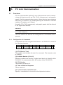
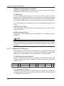
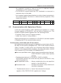
Chapter 5 PC Link Communication
5.4.5
BRS
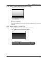
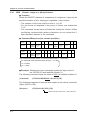
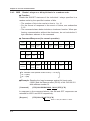
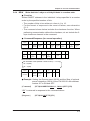
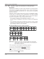
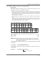
Specifies I relays to be monitored on a bit-by-bit basis.
● Function
Specifies the numbers of I relays to be monitored on a bit-by-bit basis.
Note that this command simply specifies I relays. Actual monitoring is
performed by the BRM command after the I relay numbers are specified
with this command.
When the volume of data is large and you wish to increase the communication rate, it is effective to use a combination of the BRS and BRM
commands rather than the BRD or BRR command. If the power supply is
turned off, the specified I relay numbers will be erased.
• The number of registers to be specified at a time is 1 to 16.
• For the format of response in the event of failure, see subsection
5.1.2.
• The command shown below includes the checksum function. When
performing communication without the checksum, do not include the 2byte checksum element in the command.
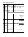
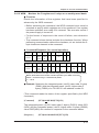
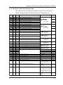
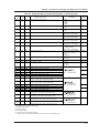
● Command/Response (for normal operation)
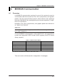
Number of
Bytes
Command
element
1
2
2
1
3
2
5
1
5
1
STX
Address
(Station
number)
CPU
number
01
0
BRS
Number
of bits
(n)
I relay
number
1
Comma
or
space
I relay
number
2
Comma
or
space
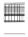
Command (continued)
Number of
Bytes
Response
element
5
2
1
1
I relay
number
n
Check
sum
ETX
CR
1
2
2
2
2
1
1
STX
Address
(Station
number)
CPU
number
01
OK
Check
sum
ETX
CR
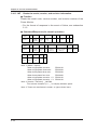
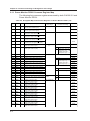
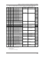
● Example: Monitoring the Input overrange against full input scale
(I0001) and the Remote reset (I0010) of the CW120/121
with address number 01.
(This command is used simply for specifying registers.)
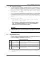
[Command] [STX]01010BRS01I0001,I0010[ETX][CR]
“OK” is returned in response to the command above.
[Response] [STX]0101OK[ETX][CR]
5-10
IM CW120C-E