1
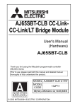
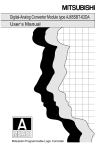
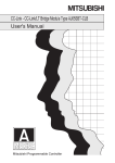
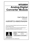
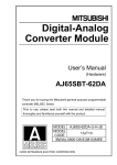
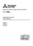
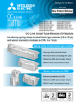
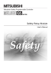
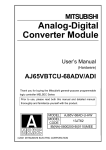
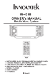
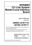
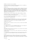
AJ65SBT-CLB CC-LinkCC-Link/LT Bridge Module
User’s Manual
(Hardware)
AJ65SBT-CLB
Thank you for buying the Mitsubishi programmable controller
MELSEC Series
Prior to use, please read both this manual and detailed manual
thoroughly to fully understand the product.
MODEL AJ65SBT-CLB-U-HW
MODEL
13JP11
CODE
IB(NA)-0800240-C(0804)MEE
©2002 MITSUBISHI ELECTRIC CORPORATION
z SAFETY PRECAUTIONS z
(Be sure to read these instructions before using the product.)
Before using this product, read this manual and the relevant manuals introduced
in this manual carefully and handle the product correctly with full attention to
safty.
Note that these precautions apply only to this product. Refer to the user's manual
of the CPU module for the PLC system safety precautions.
In this manual, the safety instructions are ranked as "DANGER" and "CAUTION".
DANGER
Indicates that incorrect handling may cause hazardous
conditions, resulting in death or severe injury.
CAUTION
Indicates that incorrect handling may cause hazardous
conditions, resulting in minor or moderate injury or property
damage.
Note that the failure to observe
CAUTION level instructions may also lead to
serious results according to the circumstances.
Be sure to observe the precautions of both levels to ensure personal safety.
Please keep this manual in accessible place and be sure to forward it to the end
user.
[DESIGN PRECAUTIONS]
DANGER
z When there are communication problems with the data link, the data for the
master module will be held.
Configure an interlocking circuit in a sequence program so that the safety of
the overall system is always maintained.
CAUTION
z Do not bunch the control wires or communication cables with the main circuit
or power wires, or install them close to each other.
They should be installed 100mm (3.9inch) or more from each other.
Not doing so could result in noise that would cause erroneous operation.
z Do not write data to the "reserved areas" of the remote I/O and remote
devices.
Doing so can pose the risk of malfunctioning the product.
A-1
[INSTALLATION PRECAUTIONS]
CAUTION
z Use each product in an environment as specified in the “general
specification” in the detailed manual.
Using the PLC outside the range of the general specifications may result in
electric shock, fire or malfunction, or may damage or degrade the product.
z Securely fix the product to a DIN rail or securely fix it with the Module
mounting screw.
Not doing so can cause a drop or malfunction.
z Do not touch the conducted area or electric parts of the product.
Doing so may cause product malfunctioning or breakdowns.
[WIRING PRECAUTIONS]
CAUTION
z For the CC-Link/LT, use the cables specified by the CC-Link Partner
Association.The performance of the CC-Link/LT cannot be assured if any
other cables than the specified are used.
Also, observe the network wiring specifications given in Chapter 2.Normal
data communication is not guaranteed if the wiring is not conducted
according to the specifications.
z Be sure to shut off all phases of the external power supply used by the
system before installation or wiring.
Not doing so can cause the product to be damaged or malfunction.
z Always ground the FG terminal to the protective ground conductor.
Not doing so can cause a malfunction.
z Wire the product correctly after confirming the rated voltage and pin layout of
the product.
Not doing so can cause a fire or failure.
z Ensure that no foreign matter such as chips and wire-offcuts enter the
product.
Foreign matter can cause a fire, failure or malfunction.
A-2
[WIRING PRECAUTIONS]
CAUTION
z Be sure to fix the wires or cables by ducts or clamps when connecting them
to the module. Failure to do so may cause damage of the module or the
cables due to accidental pull or unintentional shifting of the cables, or
malfunctions due to poor contact of the cable.
z Do not install the control lines together with the communication cables, or
bring them close to each other. Failure to do so may cause malfunctions due
to noise.
z When disconnecting the communication and power supply cables from the
module, do not hold and pull the cable part.
Disconnect the cables after loosening the screws in the portions connected
to the module. Pulling the cables connected to the module can damage the
module and cables or can cause a malfunction due to a cable connection
fault.
[STARTING AND MAINTENANCE PRECAUTIONS]
CAUTION
z Do not touch the pin while the power is on. Doing so may cause malfunction.
z Be sure to shut off all phases of the external power supply used by the
system before cleaning.
Not doing so can cause the product to fail or malfunction.
z Never disassemble or modify the product.
This may cause breakdowns, malfunctioning, injury and/or fire.
z Do not drop the product or give it hard impact since its case is made of resin.
Doing so can damage the product.
z Be sure to shut off all phases of the external power supply used by the
system before mounting or dismounting the product to or from the panel.
Not doing so can cause the product to fail or malfunction.
z Before handling the module, always touch grounded metal, etc. to discharge
static electricity from the human body.
Failure to do so can cause the module to fail or malfunction.
[DISPOSAL PRECAUTIONS]
CAUTION
z When disposing of this product, treat it as industrial waste.
A-3
Revisions
* The manual number is noted at the lower left of the back cover.
Print Date
Oct.,2002
Nov.,2004
*Manual Number
IB(NA)-0800240-A
IB(NA)-0800240-B
Apr.,2008
IB(NA)-0800240-C
Revision
First printing
Correction
SAFETY PRECAUTIONS, Section 2.1,
5.1.4, 5.1.5
Correction
Manuals, Compliance with the EMC
Directive and the Low Voltage Directive,
Section 2.1, 2.2.1, 5.1
This manual confers no industrial property rights or any rights of any other kind, nor does it
confer any patent licenses. Mitsubishi electric Corporation cannot be held responsible for
any problems involving industrial property rights which may occur as a result of using the
contents noted in this manual.
© 2002 MITSUBISHI ELECTRIC CORPORATION
CONTENTS
1. Overview .......................................................................................................1
2. Specification .................................................................................................1
2.1 Performance specifications ......................................................................1
2.2 Network wiring specifications....................................................................2
2.2.1 CC-Link network wiring specifications .............................................2
2.2.2 CC-Link/LT network wiring specifications ........................................2
3. Part names and setting .................................................................................3
4. Mounting and Installation ..............................................................................7
4.1 Handling instruction .................................................................................7
4.2 Installation environment............................................................................7
5. Wiring ............................................................................................................7
5.1 Wiring of data link cables..........................................................................7
5.1.1 Connection of the CC-Link dedicated cables...................................8
5.1.2 How to wire the CC-Link one-touch connector plug.........................9
5.1.3 Connection of modules by CC-Link/LT connection cables...............9
5.1.4 How to mount the CC-Link/LT connection cable connector .............9
6. External Dimensions ...................................................................................10
A-4
Manuals
The following table list the manuals related to this product.
You can order it os necessary.
Detailed Manual
Manual name
AJ65SBT-CLB CC-Link - CC-Link/LT Bridge Module
User’s Manual
Manual No.
(Model code)
SH-080362E
(13R63)
Relerant Manual
Manual No.
(Model code)
IB-66721
(13J872)
IB-66722
(13J873)
SH-080394E
(13JR64)
Manual name
CC-Link System Master/Local Module
type AJ61BT11/A1SJ61BT11 User’s Manual
CC-Link System Master/Local Module
type AJ61QBT11/A1SJ61QBT11 User’s Manual
CC-Link System Master/Local Module
type QJ61BT11N User’s Manual
Type A80BDE-J61BT11 CC-Link System Master/Local
IB-0800175
Interface Board User’s Manual
(13JR28)
(For SW4DNF-CCLINK-B)
Type Q80BD-J61BT11N CC-Link System Master/Local
SH-080527ENG
Interface Board User’s Manual
(13JR77)
(For SW1DNC-CCBD2-B)
A-5
Compliance with the EMC Directive and the Low Voltage Directive
(1) For programmable controller system
To configure a system meeting the requirements of the EMC and Low
Voltage Directives when incorporating the Mitsubishi programmable
controller (EMC and Low Voltage Directives compliant) into other
machinery or equipment, refer to the "EMC AND LOW VOLTAGE
DIRECTIVES" chapter of the User's Manual for the CPU module used.
The CE mark, indicating compliance with the EMC and Low Voltage
Directives, is printed on the rating plate of the programmable controller.
(2) For the product
For the compliance of this product with the EMC and Low Voltage
Directives, refer to the "CC-Link module" section in the "EMC AND LOW
VOLTAGE DIRECTIVES" chapter of the User's Manual for the CPU
module used.
A-6
1. Overview
This manual describes the specifications, part names, settings, etc. of the
AJ65SBT-CLB CC-Link - CC-Link/LT bridge module (hereafter abbreviated to
the AJ65SBT-CLB) used as a remote device station in a CC-Link system.
After unpacking, confirm that the following product is contained.
Item name
Number of items
AJ65SBT-CLB CC-Link - CC-Link/LT bridge module
1
2. Specification
2.1 Performance specifications
The following table indicates the performance specifications of the
AJ65SBT-CLB.
Refer to the detailed manual for the general specifications.
Item
Specifications
Remote device station
Ver.1.10
64 points each for RX and RY (16 points are used in the
2 stations
system)
8 points each for RWr and RWw
128 points each for RX and RY (16 points are used in the
Number of
occupied
4 stations
system)
stations
16 points each for RWr and RWw
256 points each for RX and RY (32 points are used in the
8 stations
(4 occupied stations 2 system)
modules)
32 points each for RWr and RWw
AJ65SBT-CLB connection position
No restrictions
One-touch connector for communication [transmission
circuit] (5-pin, insulation displacement type connector plug
External connection system
is sold separately)
<Option> Online connector for communication:
A6CON-LJ5P
4-point mode
8-point mode
16-point mode
Maximum number of link points
Number in parentheses
224 points (448 points)
assumes use of the same I/O
addresses
Number of link points per station
Number in parentheses
4 points
8 points
16 points
assumes use of the same I/O
(8 points)
(16 points)
(32 points)
addresses
Transmission speed
2.5Mbps/625kbps/156kbps
Communication method
Broadcast polling method
Transmission path format
T-branch system
Error control system
CRC
Number of connected modules 56 modules
Remote station number
1 to 56
AJ65SBT-CLB connection
Connected at the end of the main line
position
Network diagnosis, internal loopback diagnosis, slave
RAS functions
station separation, automatic return to system
Dedicated flat cable (0.75mm2 4) *4, VCTF cable *3, High
Connection cable *1
flexible cable *4
Communication specifications
CC-Link/LT side
Control
specifications
CC-Link side
Station type
CC-Link Version
1
Item
Specifications
M4 0.7mm 16mm or more screw
Tightening torque range 78 to 108N cm
DIN rail can also be used for mounting.
Can be mounted in any of six orientations.
(No restrictions on mounting directions)
24VDC externally supplied (20.4V DC to 26.4V DC, ripples
within 5%)
Common
Module mounting screw
Module mounting direction
Voltage
24VDC power
supply *2
Current
consumption
Start-time current
Level of protection
Weight
0.075A (24V DC)
0.165A (24V DC)
IP2X
0.09kg
*1 Performance of the CC-Link/LT cannot be guaranteed for use of cables other
than the dedicated flat cables, VCTF cables and high flexible cables.
*2 Supplied by a CC-Link/LT dedicated power supply or power supply adaptor.
*3 For VCTF cable specifications, see Table 2.1.
*4 Use the dedicated flat cables and high flexible cables accredited by the
CC-Link Partner Association.
CC-Link Partner Association’s website: http://www.cc-link.org/
Table 2.1 VCTF cable specifications (Extract from JIS C 3306)
Type
Conductor
No. of
Insulator Sheath
Nominal
Composition
cores cross-sectional No. of wires/wire Outside thickness thickness
diameter
area
diameter
Vinyl cabtyre,
Round cord
4
2
0.75mm
30/0.18mm
1.1mm
0.6mm
1.0mm
Conductor
resistance
(20 )
25.1Ω/km
2.2 Network wiring specifications
2.2.1 CC-Link network wiring specifications
For the network wiring specifications of CC-Link, refer to the user's manual of the
used master module.
2.2.2 CC-Link/LT network wiring specifications
This section describes the system configuration of the CC-Link/LT.
Item
Transmission speed
Distance between stations
Max. no. of connectable
modules per drop line
Length of trunk line
2.5 Mbps
Specifications
625 kbps
Not limited
Remarks
156 kbps
8 modules
35 m
T-branch interval
100 m
500 m
Cable length between
terminating resistors. Length
of drop lines not included
Not limited
Max. length of drop line
4m
16 m
60 m
Max. cable length per branch
line
Overall length of drop
lines
15 m
50 m
200 m
Total length of all drop lines
2
Master
station
Remote
device station
Remote
I/O station
Remote
I/O station
Length of trunk line (Drop line not included)
CC-Link side
AJ65SBT-CLB
CC-Link/LT side
T-branch
Length
of
connection
Terminating
resistor
drop
line
Interval length of T-branch
Power
supply
adapter
Length
of
drop
line
Remote
station
*1 *2
Remote
station
Remote
station
Remote
station
Remote
station
Terminating
resistor
Remote
station
Remote
station
Distance
between stations
Remote
station
Remote
station
Trunk line
Drop line
Remote
station
*1 The length of drop line includes the length of 2. (The max. length of drop line
and overall length of drop lines include the length of 2.)
3. Part names and setting
This chapter describes part names.
1)
CC-Link
Diagram 1
CC-Link/LT
CC-Link
PW L RUN L ERR. LRUN L ERR. ERR.
A J65SBT-CLB
STATION NO. BRATE NOS TSTMODEBRATE NC
402010 8 4 2 1 4 2 1 2 1
2 1 2 1
1 2 3 4 5 6 7 8 9 10 1 2 3 4 5 6 7 8
ON
2)
CC-Link
(FG)
6)
CC-Link/LT
CC-Link/LT
3)
4)
5)
3
Number
1)
Name
Description
Shows the module status by turning the LED on/off.
LED name
Description
CC-Link side
CC-Link/LT side
On: Module normal
PW
Off: Module fault or not supplied with power
On: Data link communication <During normal operation>
normal
On: Data link being executed
Off: Data link communication Off: Data link stopped
off (time-out)
<In self-loopback test mode>
L RUN
On: Self-loopback test
completed.
Off: Self-loopback test failed
On: CC-Link side switch
<During normal operation>
setting fault
On: Data link error station
Data link communication
(detected)
LED display
fault
Station outside control
Flicker: CC-Link side switch
range detected
setting is changed
Flicker: Data link error stations
L ERR.
during operation.
(all stations)
Off: No faults
Off: No faults
<In self-loopback test mode>
On: Self-loopback test failed
Off: Self-loopback test
completed
Setting error detection
On: CC-Link/LT side switch
setting fault
Flicker:
CC-Link/LT side switch
ERR.
setting is changed
during operation.
Off: No faults
4
Diagram 1
CC-Link
CC-Link/LT
STATION NO. BRATE NOS TST MODE BRATE NC
402010 8 4 2 1 4 2 1 2 1
2 1 2 1
1 2 3 4 5 6 7 8 9 10 1 2 3 4 5 6 7 8
ON
1 2 3 4 5 6 7 8 910 1 2 3 4 5 6 7 8
Number
Name
Station
number
setting
switches
(CC-Link side)
STATION NO.
Case silkscreen No.*
*: The case silkscreen No. and
switch silkscreen No. correspond
to each other.
Switch silkscreen No.*
Description
Use the switches in STATION NO. "10", "20" and "40" to set the tens of the
station number.
Use the switches in STATION NO. "1", "2", "4" and "8" to set the units of the
station number.
Tens
Units
Station
Number
40
20
10
8
4
2
1
1
OFF
OFF
OFF
OFF
OFF
OFF
ON
2
OFF
OFF
OFF
OFF
OFF
ON
OFF
3
OFF
OFF
OFF
OFF
OFF
ON
ON
10
11
OFF
OFF
OFF
OFF
ON
ON
OFF
OFF
OFF
OFF
OFF
OFF
OFF
ON
63
ON
ON
OFF
OFF
OFF
ON
ON
The switches are all factory-set to OFF.
The station number can be set within the range 1 to 63 when two stations
are occupied, 1 to 61 when four stations are occupied, or 1 to 57 when
eight stations (four occupied stations two modules) are occupied.
Setting a value other than the above will result in a setting error. (The "L
ERR." LED on the CC-Link side is lit.)
2)
Setting Switches
Setting
Transmission Speed
Value
4
2
1
Transmission
0
OFF
OFF
OFF
156 kbps
speed setting
(factory-set)
switches
1
OFF
OFF
ON
625 kbps
(CC-Link side)
2
OFF
ON
OFF
2.5 Mbps
B RATE
3
OFF
ON
ON
5.0 Mbps
4
ON
OFF
OFF
10 Mbps
Setting a value other than the above will result in a setting error. (The "L
ERR." LED on the CC-Link side is lit.)
Number of
Setting
Number of occupied
Setting Switches
occupied
Value
stations
2
1
stations
0
setting
OFF
OFF
2 stations
(factory-set)
switches
1
OFF
ON
4 stations
(CC-Link side)
8
stations
NOS:
2
ON
OFF
(four occupied stations
Numbers of
two modules)
Occupied
Setting
a
value
other
than
the
above
will
result
in
a
setting
error. (The "L
stations
ERR." LED on the CC-Link side is lit.)
5
Number
2)
Name and
appearance
Self-loopback
test setting
switch
(CC-Link/LT
side)
TST
4)
5)
6)
OFF: Normal operation mode (factory-set)
ON: Self-loopback test mode
Setting
Setting Switches
Points
Value
2
1
Point mode
setting switches
0
OFF
OFF
8 points
(CC-Link/LT
(factory-set)
side)
1
OFF
ON
4 points
MODE
2
ON
OFF
16 points
Setting a value other than the above will result in a setting error. (The "L
ERR." LED on the CC-Link/LT side is lit.)
Transmission
speed setting
switches
(CC-Link/LT
side)
B RATE
3)
Description
One-touch
connector for
communication
CC-Link/LT
Interface
connector
DIN rail hook
FG terminal
Setting Switches
Setting
Transmission Speed
Value
2
1
0
OFF
OFF
156 kbps
(factory-set)
1
OFF
ON
625 kbps
2
ON
OFF
2.5 Mbps
Setting a value other than the above will result in a setting error. (The "L
ERR." LED on the CC-Link/LT side is lit.)
A one-touch connector for communication line connection.
Connect two optional one-touch connector plugs for communication to
the connectors during wiring top and bottom.
Connector for CC-Link/LT communication line connection.
Used to mount the module to the DIN rail.
Ground terminal
6
4. Mounting and Installation
4.1 Handling instruction
This section explains the handling instruction of the module.
Be careful not to drop it or expose the module case to strong impact, since it is
made of resin.
4.2 Installation environment
Use the module in the environment that meets the general specifications
described in the tailed manual.
Failure to observe this instruction can cause an electric shock, fire, malfunction,
damage to the product, or deterioration.
Tighten the module mounting screws and terminal block screw within the
following ranges.
Screw Location
Module mounting screw (M4 screw)
FG terminal block terminal screw (M3 screw)
Tightening Torque Range
78 to108 N cm
42 to 58 N cm
5. Wiring
5.1 Wiring of data link cables
7
5.1.1 Connection of the CC-Link dedicated cables
Connect the CC-Link dedicated cable between the AJ65SBT-CLB and master
module as shown below.
One-touch connector plug
for communication
Online connector for
communication
54 32 1
5 4 3 2 1
One-touch connector plug
with terminating resistor
A6CON-TR11
[CC-Link dedicated cable wiring diagram]
Terminating
resistor
(Blue)
Master module
NC
DA
(White)
NC
DB
NC
(Yellow)
(Blue)
(White)
(Yellow)
SLD
NC
(Blue)
(White)
(Yellow)
NC
SLD
DG
SLD
FG
Online connector
for communication
Online connector
for communication
1
2
3
4
5
CONA
1 DA
2 DB
3 DG
4 NC
5 SLD
1
2
3
4
5
CONB
1 DA
2 DB
3 DG
4 NC
5 SLD
(Blue)
(White)
(Yellow)
SLD
Terminating
resistor
(A6CON-TR11)
1
2
3
4
5
CONA
1 DA
2 DB
3 DG
4 NC
5 SLD
1
2
3
4
5
CONB
1 DA
2 DB
3 DG
4 NC
5 SLD
FG
Ver.1.10 Compatible CC-Link dedicated cable (FANC-110SBH,CS-110,FA-CBL200PSBH)
Point
• For this module, use the Ver. 1.10-compatible CC-Link dedicated cable
(FANC-110SBH,CS-110,FA-CBL200PSBH).
You cannot use the Ver. 1.10-compatible CC-Link dedicated cables other than
the above types, CC-Link dedicated cables or CC-Link dedicated,
high-performance cables.
• The shield wire of the CC-Link dedicated cable should be connected to “SLD”
in each module, and both ends should be grounded through “FG”.
“SLD” and “FG” are connected inside the module.
8
5.1.2 How to wire the CC-Link one-touch connector plug
For details of how to wire the one-touch connector plug, refer to the
AJ65SBT-CLB CC-Link - CC-Link/LT Bridge Module User's Manual.
5.1.3 Connection of modules by CC-Link/LT connection cables
For details of how to connect the modules by the CC-Link/LT connection cables,
refer to the AJ65SBT-CLB CC-Link - CC-Link/LT Bridge Module User's Manual.
(1) The station number is not relevant to the order of connecting the
connection cables.
(2) Be sure to place the AJ65SBT-CLB at one end of the main line. Also,
connect the AJ65SBT-CLB side terminating resistor within 20cm of the
AJ65SBT-CLB.
(3) Always connect terminating resistors at both ends of the CC-Link/LT trunk
line.
(4) For required number of the connectors, refer to the AJ65SBT-CLB CC-Link
- CC-Link/LT Bridge Module User’s Manual.
5.1.4 How to mount the CC-Link/LT connection cable connector
For details of how to mount the CC-Link/LT connection cable connector, refer to
the AJ65SBT-CLB CC-Link - CC-Link/LT Bridge Module User's Manual.
9
6. External Dimensions
40 (1.57)
[AJ65SBT-CLB]
CC-Link/LT
CC-Link
A
J65SBT-CLB
ON
CC-Link
CC-Link/LT
10
(0.39)
Center of DIN rail
2-4.5 5.1 mounting hole (M4 mounting screw)
4.5
(0.18)
41
(FG)
CC-Link/LT
STATION NO. BRATE NOS TST MODE BRATE NC
402010 8 4 2 1 4 2 1 2 1
2 1 2 1
1 2 3 4 5 6 7 8 9 10 1 2 3 4 5 6 7 8
0.01) [4]
(0.16)
49 (1.93)
CC-Link
PW LRUN L ERR. L RUN LERR. ERR.
[4.5] (0.18)
0.2 (1.61
78
22 (0.87)
87 (3.43)
0.4 (3.07 0.02)
Unit:mm(inch)
10
Warranty
Mitsubishi will not be held liable for damage caused by factors found not to be the cause of
Mitsubishi; machine damage or lost profits caused by faults in the Mitsubishi products;
damage, secondary damage, accident compensation caused by special factors
unpredictable by Mitsubishi; damages to products other than Mitsubishi products; and to
other duties.
For safe use
y This product has been manufactured as a general-purpose part for general industries, and
has not been designed or manufactured to be incorporated in a device or system used in
purposes related to human life.
y Before using the product for special purposes such as nuclear power, electric power,
aerospace, medicine or passenger movement vehicles, consult with Mitsubishi.
y This product has been manufactured under strict quality control. However, when installing
the product where major accidents or losses could occur if the product fails, install
appropriate backup or failsafe functions in the system.
Country/Region Sales office/Tel
Country/Region Sales office/Tel
U.S.A
Mitsubishi Electric Automation Inc.
Hong Kong
Mitsubishi Electric Automation
(Hong Kong) Ltd.
500 Corporate Woods Parkway Vernon
10th Floor, Manulife Tower, 169 Electric
Hills, IL 60061, U.S.A.
Road, North Point, Hong Kong
Tel : +1-847-478-2100
Tel : +852-2887-8870
Brazil
MELCO-TEC Rep. Com.e Assessoria
China
Mitsubishi Electric Automation
Tecnica Ltda.
(Shanghai) Ltd.
Rua Correia Dias, 184,
4/F Zhi Fu Plazz, No.80 Xin Chang Road,
Edificio Paraiso Trade Center-8 andar
Shanghai 200003, China
Paraiso, Sao Paulo, SP Brazil
Tel : +86-21-6120-0808
Tel : +55-11-5908-8331
Taiwan
Setsuyo Enterprise Co., Ltd.
Germany
Mitsubishi Electric Europe B.V. German
6F No.105 Wu-Kung 3rd.Rd, Wu-Ku
Branch
Hsiang, Taipei Hsine, Taiwan
Gothaer Strasse 8 D-40880 Ratingen,
Tel : +886-2-2299-2499
GERMANY
Korea
Mitsubishi Electric Automation Korea
Co., Ltd.
Tel : +49-2102-486-0
1480-6, Gayang-dong, Gangseo-ku
U.K
Mitsubishi Electric Europe B.V. UK
Seoul 157-200, Korea
Branch
Tel : +82-2-3660-9552
Travellers Lane, Hatfield, Hertfordshire.,
Singapore
Mitsubishi
Electric Asia Pte, Ltd.
AL10 8XB, U.K.
307 Alexandra Road #05-01/02,
Tel : +44-1707-276100
Mitsubishi Electric Building,
Italy
Mitsubishi Electric Europe B.V. Italian
Singapore 159943
Branch
Tel : +65-6470-2460
Centro Dir. Colleoni, Pal. Perseo-Ingr.2
Thailand
Mitsubishi Electric Automation (Thailand)
Via Paracelso 12, I-20041 Agrate Brianza.,
Co., Ltd.
Milano, Italy
Bang-Chan Industrial Estate No.111
Tel : +39-039-60531
Moo 4, Serithai Rd, T.Kannayao,
Spain
Mitsubishi Electric Europe B.V. Spanish
A.Kannayao, Bangkok 10230 Thailand
Branch
Tel : +66-2-517-1326
Indonesia
P.T. Autoteknindo Sumber Makmur
Carretera de Rubi 76-80,
Muara Karang Selatan, Block A/Utara
E-08190 Sant Cugat del Valles,
No.1 Kav. No.11 Kawasan Industri
Barcelona, Spain
Pergudangan Jakarta - Utara 14440,
Tel : +34-93-565-3131
P.O.Box 5045 Jakarta, 11050 Indonesia
France
Mitsubishi Electric Europe B.V. French
Tel
: +62-21-6630833
Branch
India
Messung Systems Pvt, Ltd.
25, Boulevard des Bouvets, F-92741
Electronic Sadan NO:III Unit No15,
Nanterre Cedex, France
M.I.D.C Bhosari, Pune-411026, India
TEL: +33-1-5568-5568
Tel : +91-20-2712-3130
South Africa
Circuit Breaker Industries Ltd.
Australia
Mitsubishi Electric Australia Pty. Ltd.
Private Bag 2016, ZA-1600 Isando,
348 Victoria Road, Rydalmere,
South Africa
N.S.W 2116, Australia
Tel : +27-11-928-2000
Tel : +61-2-9684-7777
HEAD OFFICE : TOKYO BUILDING, 2-7-3 MARUNOUCHI, CHIYODA-KU, TOKYO 100-8310, JAPAN
NAGOYA WORKS : 1-14, YADA-MINAMI 5-CHOME, HIGASHI-KU, NAGOYA, JAPAN
When exported from Japan, this manual does not require application to the Ministry
of Economy, Trade and Industry for service transaction permission.
Specifications subject to change without notice.
Printed in Japan on recycled paper.