Download Manual for install
Transcript
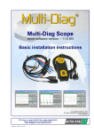
1) Multi-Diag Office
(since SW version – 11.1)
2) Multi-Diag Scope
(since SW version – 10.1, incl. Multi-Diag Motortester)
BASIC INSTRUCTIONS
Programs of Multi-Diag family is not possible install on the windows 9x/me operating system.
If you install the program into a computer with Windows 2000, XP, Vista or 7
operation systems, you must have administrator rights (see Chap. 6.1) and it is recommended to have the device
connected to the Internet (see Chap. 6.3).
Warning: Since version SW 10.2, the support to the 4-day trial version of the programme was
terminated (see Chap. 6.2).
Last updated: May 24, 2011
The right is reserved to change the Manual
ATAL spol. s r.o., Lesní 47, 390 01 Tábor - Horky, Czech Republic
Phone: +420 381 256 392, 381 251 791; Fax: +420 381 253 043
e-mail: [email protected]; web: http://www.atal.cz
DIAGNOSTICS_INST_MANUAL_EN--111--POCKET2.DOC
14.5.2007
změna návodu vyhrazena
CONTENTS
1.
2.
3.
4.
INTRODUCTION................................................................................................................................................................................................................................ ....................3
HOST COMPUTER REQUIREMENTS..................................................................................................................................................................................................................3
IMPORTANT NOTICE ...........................................................................................................................................................................................................................................3
WASTE DISPOSAL ...............................................................................................................................................................................................................................................3
5.1
5.2
5.3
6.
6.1
6.1.1
6.1.2
6.2
6.3
6.3.1
6.3.2
7.
BASIC PARAMETERS...........................................................................................................................................................................................................................................3
STARTING DEVICE AND DESCRIPTION OF PORTS .........................................................................................................................................................................................4
BUTTONS AND LIGHTS .......................................................................................................................................................................................................................................4
INSTALLATION CD DESCRIPTION AND ITS RUNNING .....................................................................................................................................................................................4
POSSIBLE INSTALLATION PROBLEM ON WINDOWS VISTA / 7.......................................................................................................................................................................4
DISABLE THE UAC (USER ACCOUNT CONTROL) – WINDOWS VISTA ...........................................................................................................................................................5
DISABLE THE UAC (USER ACCOUNT CONTROL) – WINDOWS 7....................................................................................................................................................................5
SOFTWARE PROTECTION SYSTEM...................................................................................................................................................................................................................5
WARNING AND RECOMMENDATION FOR THE INTERNET CONNECTION.....................................................................................................................................................5
THE DEVICE WILL DISPOSE OF A FUNCTIONAL INTERNET CONNECTION ..................................................................................................................................................5
THE DEVICE WILL NOT DISPOSE OF A FUNCTIONAL INTERNET CONNECTION..........................................................................................................................................6
MULTI-DIAG FAMILY PROGRAMS – INSTALLATION, CONTROL AND CONFIGURATION ..............................................................................................................................6
5.
TABLET PC .............................................................................................................................................................. 3
7.1
7.1.1
7.1.2
7.1.3
7.1.4
7.1.5
7.1.6
7.1.6.1
7.1.6.2
7.1.7
7.1.8
7.1.8.1
7.1.8.2
7.2
7.2.1
7.2.1.1
7.2.1.2
7.2.2
7.2.2.1
7.2.3
7.3
7.3.1
7.3.2
MULTI-DIAG OFFICE AND MULTI-DIAG PROGRAMS INSTALLATION ............................................................... 6
INSTALLATION DIAGRAM (DEVELOPMENT DIAGRAM) FOR MULTI-DIAG OFFICE........................................................................................................................................7
REQUIREMENT FOR ENTERING THE SERIAL NUMBER OF VCI .....................................................................................................................................................................7
REQUIREMENT FOR THE AUTHORIZATION CODE (ALWAYS OVER THE PHONE) .......................................................................................................................................9
REQUIREMENT FOR THE LICENCE VERIFICATION .........................................................................................................................................................................................9
MULTI-DIAG OFFICE CONFIGURATION ...........................................................................................................................................................................................................12
MULTI-DIAG CONFIGURATION VCI ..................................................................................................................................................................................................................13
VCI SERIAL NUMBER ENTERING .....................................................................................................................................................................................................................13
MULTI-DIAG CONFIGURATION VCI - BLUETOOTH .........................................................................................................................................................................................14
MULTI-DIAG START UP......................................................................................................................................................................................................................................15
MULTI-DIAG CONTROL......................................................................................................................................................................................................................................15
EXAMPLE OF DIAGNOSTICS START THROUGH VIN CODE .........................................................................................................................................................................15
EXAMPLE OF DIAGNOSTICS START THROUGH LIST OF AVAILABLE VEHICLES .......................................................................................................................................16
MULTI-DIAG SCOPE INSTALLATION................................................................................................................... 17
PROGRAM AUTO UPDATE ................................................................................................................................................................................................................................19
AUTO UPDATE INDICATION ON THE SCREEN................................................................................................................................................................................................19
AUTO UPDATE INDICATION ON MULTI-DIAG SCOPE ....................................................................................................................................................................................19
MULTI-DIAG SCOPE START UP ........................................................................................................................................................................................................................20
ERROR MESSAGE WHEN MULTI-DIAG SCOPE IS DISCONNECTED ............................................................................................................................................................20
CONTROL OF INDIVIDUAL FUNCTIONS AND SETTING OF PARAMETERS ..................................................................................................................................................21
NEWLY RECOGNISED HARDWARE (HW) INSTALLATION................................................................................ 21
INSTALLATION OF ATAL DEVICES – GENERAL ..............................................................................................................................................................................................21
ADAPTER USB-RS232 FINAL INSTALLATION ..................................................................................................................................................................................................21
Diagnostics_inst_manual_en--111--pocket2.doc
—2—
Multi-Diag - Basic instructions for installations
1.
INTRODUCTION
Detailed description, user’s manual and necessary program equipment are placed on the CD that makes part of the
basic set.
Here you will find basic information about the Multi-Diag diagnostic system you have to know when unwrapping
individual parts and the setting procedure basic parameters for the communication of Multi-Diag with the computer.
2.
HOST COMPUTER REQUIREMENTS
Windows 2000/XP/Vista/7
Windows 7 (32 bit) for M-D Scope
VGA 800x640/16bits
CD ROM drive
3.
•
Processor: Intel Pentium 400 MHz compatible and faster
RAM 256 MB (minimum), 512 MB (recommended)
Free RS 232 or USB port
IMPORTANT NOTICE
Before Windows re-installation is necessary connect the USB splitter with at least 2 USB ports selfpowered for connection of the keyboard and DVD drive. When you install Multi-Diag Office, you can already use
the virtual keyboard, that can be launched as is on Fig. 3.
Multi-Diag shall be operated in compliance with the User’s Manual.
The communication interface (VCI) should not be connected to vehicle before Multi-Diag Pocket 2 is started
(first, start the computer, second, connect the VCI to diagnostic plug)
For operating Tablet PC, you shall use only the supplied „pen“ so as not to damage the touch-screen.
Do not use the diagnostic tool in the rain and do not put in on wet surfaces.
Do not put the diagnostic tool on hot surfaces.
The device shall not be transported or temporarily stored on open platforms which are not protected against rain
or in vehicles or rooms where acids, chlorine, mercury vapours etc. can be present.
To clean it, use suitable detergents (cleansing articles for screens of monitors). Do not use solvents.
Non-usable batteries are a dangerous waste and shall be handled accordingly. They shall not be disposed in the
ordinary communal garbage.
The universal adapter (AT 107 3086) should be connected to the vehicle battery first and only after that to the
Multi-Diag VCI.
If you install the program into a computer with Windows 2000/XP/Vista/7 operation systems, you must have
administrator rights (see Chap. 6.1).
•
•
•
•
•
•
•
•
•
•
4.
WASTE DISPOSAL
A NOTE ABOUT RECYCLING:
This product's packaging materials are recyclable and can be reused. Please dispose of any materials in
accordance with the local recycling regulations.
When discarding the unit, comply with local roles or regulations.
Batteries should never be thrown away or incinerated but disposed of in accordance with the local
regulations concerning chemical waste.
This product and the accessories packed together constitute the applicable product according to the WEEE
directive except batteries
5.
TABLET PC
TABLET PC is a PC-based diagnostic terminal. Its ergonomics and robustness and its control by means of touch screen
fulfils high requirements for the use in the workshop.
5.1
BASIC PARAMETERS
µP ...................................................... Intel ATOM 1.2 GHz
Memory.............................................. 1 GB
HDD................................................... SSD 16GB
OS – Platform .................................... Windows 7 Home Premium OEM
Diagnostics_inst_manual_en--111--pocket2.doc
—3—
Multi-Diag - Basic instructions for installations
Screen............................................... 1024 x 600 (Widescreen)
Display .............................................. Color 7", Touch Screen
Working............................................. 5 h. (in use) / 6 h. (sleeping)
Expresd diag time (average)............. 1min 55s
Dimension ......................................... 22.1 x 11.7 x 2.25 cm
Weight............................................... 660g
WLAN................................................ WiFi 802.11b/g
BlueTooth.......................................... 2.0+EDR
Multimedia......................................... Microphone, webcam
5.2
STARTING DEVICE AND DESCRIPTION OF PORTS
Fig. 1 – Description of ports
5.3
Fig. 2 – Starting device
BUTTONS AND LIGHTS
Fig. 3 – Buttons and lights
6.
INSTALLATION CD DESCRIPTION AND ITS RUNNING
The attached CD contains all the necessary software for the use of Multi-Diag system including the accompanying files
such as user’s manuals, prospectuses and the most used service procedures.
Insert the CD in your CD-ROM drive. If the CD does not run automatically, run the autorun.exe program which you will
find on the CD.
6.1
POSSIBLE INSTALLATION PROBLEM ON WINDOWS VISTA / 7
Before you install Office Multi-Diag on Windows Vista or Windows 7, it is necessary to ensure the following conditions:
§
§
§
The actual Multi-Diag Office program must not be running.
YOU MUST have administrator rights!
YOU MUST disable the UAC (User Account Control) service – see Chap. 6.1.1 or 6.1.2
Diagnostics_inst_manual_en--111--pocket2.doc
—4—
Multi-Diag - Basic instructions for installations
o
o
6.1.1
Following these changes, it is necessary to restart the computer
After installation, do not forget to set the default values and restart the system!
DISABLE THE UAC (USER ACCOUNT CONTROL) – WINDOWS VISTA
For Windows Vista UAC (User Account Control) off as follows:
§ In "Control Panel" (Start/Control Panel) go to the section
"User Account"
§ Go to the section "Turn User Account Control on or off”
§ Tick appropriate box - see picture
Fig. 4 – Disable the UAC – Windows Vista
Notice:
After installation, do not forget to set the default values and restart the system!
6.1.2
DISABLE THE UAC (USER ACCOUNT CONTROL) – WINDOWS 7
For Windows 7 UAC (User Account Control) off as follows:
§ In "Control Panel" (Start/Control Panel) go to the section
"User Account and family Safety"
§ Go to the section "Change User Account Control
setting“
§ In the "Always notify" to reduce the value of the slider to
"Newer notify" – see picture
Fig. 5 – Disable the UAC – Windows 7
Notice:
After installation, do not forget to set the default values and restart the system!
6.2
SOFTWARE PROTECTION SYSTEM
§
§
Since version SW Multi-Diag 9.2 version introduces a new software protection system. The activation password
can be requested after Multi-Diag launch or during of Multi-Diag work depending on your license. The activation
password shouldn’t be requested in case of version upgrade.
Since version Multi-Diag SW 10.2, the support to the 4-day trial version of the programme was terminated
6.3
WARNING AND RECOMMENDATION FOR THE INTERNET CONNECTION
Prior to proceeding with the installation, it is recommended to have the device connected to the Internet.
6.3.1
THE DEVICE WILL DISPOSE OF A FUNCTIONAL INTERNET CONNECTION
If the device has a functional Internet connection, all SW-HW authorization will proceed
automatically and the installations will ensue automatically after a certain time limit.
We therefore recommend connecting the device to the Internet prior to any update and verify this
connection for reliability and integrity (e.g. open a browser and click on any link). Only then launch
the actual installation or update.
Diagnostics_inst_manual_en--111--pocket2.doc
—5—
Multi-Diag - Basic instructions for installations
6.3.2
THE DEVICE WILL NOT DISPOSE OF A FUNCTIONAL INTERNET CONNECTION
If the device does not have a functional Internet connection, all authorizations (entering the
authorization code) will be performed manually and over the phone with the authorization centre
(Hot Line) of ATAL spol. s r.o. Tábor or potentially via your dealer.
7.
MULTI-DIAG FAMILY PROGRAMS – INSTALLATION, CONTROL AND CONFIGURATION
Multi-Diag Office installations (see Chap. 7.1) and Multi-Diag are connected to each other, Multi-Diag installation is
started automatically once Multi-Diag Office is installed.
Installation of the Multi-Diag Scope measuring system is (enables to measure and follow the courses of electrical voltage
signals) is described in Chap. 7.2.
Installation of the newly recognised hardware (HW) is described in Chap. 7.3.
7.1
MULTI-DIAG OFFICE AND MULTI-DIAG PROGRAMS INSTALLATION
Multi-Diag Office program is not possible install on the windows 9x/Me
If you install the program on the computer with Windows 2000/XP/ Vista/7 operation system, log in as a system administrator
(viz Chap. 6.1).
Select the Multi-Diag Office xx.x (Install.) option (see Fig. 6) from the menu.
Installation is intuitive – you will follow the Installation Wizard displayed on the PC screen.
The default language of the Wizard is English but it can correspond to your language version of Windows.
The installation may take several minutes. Click on "Finish" to complete the installation (see Fig. 17).
The following set of images comes from the installation wizard for the Windows XP and Win 7 operation system. The
Windows Vista wizard is similar:
Fig. 6 – Menu for Multi-Diag Office installation (the right is reserved to
change the Fig.)
Diagnostics_inst_manual_en--111--pocket2.doc
Click “Next” to proceed with the installation
—6—
Multi-Diag - Basic instructions for installations
Click the <Next> button to decide about the following
installation steps, namely whether:
It is a new installation of the VCI
(Vehicle communication interface).
It is an upgrade.
Fig. 7 – Installation will continue as soon as the license conditions are
agreed on
7.1.1
INSTALLATION DIAGRAM (DEVELOPMENT DIAGRAM) FOR MULTI-DIAG OFFICE
Note:
The print-friendly version of the installation diagram (development diagram) is available at the website www.atal.cz
under the section SUPPORT (FAQ).
When installing Multi-Diag-Office, we recommend using the installation (development) diagram – see Fig. 9 depicting the
individual steps of taking decisions when verifying the validity of the licence number, authorization code and the entitlement
to use the actual installed software.
Orientation in the diagram:
The arrow indicates the path to the window where the user decides by answering either YES or NO and continues to the
next decisions in the direction of the arrow:
Blue line – positive decision
Red line – negative decision
Black line – automatic continuation
7.1.2
REQUIREMENT FOR ENTERING THE SERIAL NUMBER OF VCI
See the block diagram on Fig. 9 – section A
If it is:
A brand new installation, the box will be (pos. 1) empty
An upgrade, the box will be (pos. 1) pre-populated
Recommendation:
Prior to proceeding to another step of the installation (update),
we recommend you connect to the Internet or potentially
make sure that the device has really established a functional
connection to the Internet (see Chap. 6.3), because this
moment is critical for further installation.
1
Note:
The serial number of the VCI interface that needs to be
entered or checked (pos. 1), can be found on its reverse side
(a six-digit number) – see Fig. 28 or Fig. 9 – section A.
2
Fig. 8 – Prior to proceeding with installation, it is necessary to enter or
check the VCI number.
Diagnostics_inst_manual_en--111--pocket2.doc
—7—
Multi-Diag - Basic instructions for installations
Fig. 9 – Installation of Multi-Diag Office (verification of the serial number, authorization code and license)
Diagnostics_inst_manual_en--111--pocket2.doc
—8—
Multi-Diag - Basic instructions for installations
7.1.3
REQUIREMENT FOR THE AUTHORIZATION CODE (ALWAYS OVER THE PHONE)
See the block diagram on Fig. 9 – section B
You can skip this operation during installation but it needs to be completed at a later time anyway. The programme will not
run without the authorization code. This requirement will appear every time a new PC or VCI is connected or on the
reinstallation of the operation system.
Important warning!
The “authorization code” can be acquired only over the phone at a moment when it is necessary
to contact the authorization centre (ATAL spol. s r.o. Tábor Hot Line) or potentially via your dealer.
Prior to calling, have the following prepared:
a) 6-digit number of the VCI (see Note in 7.1.6.1)
b) A generated identifier (see Fig. 10)
1
3
3
2
5
4
Fig. 10 – Prior to further proceeding with the installation, it is necessary to enter the “activation code” and have it authorized by the authorization
centre (ATAL Hot Line or Dealer).
7.1.4
REQUIREMENT FOR THE LICENCE VERIFICATION
See block diagram on Fig. 9 – section C
Recommendation:
Prior to proceeding with the licence verification, we recommend connecting the device to the Internet or checking an existing
Internet connection for functionality (see Chap. 6.3) because the device will contact the authorization server, download the
key and will automatically proceed with the installation.
If your internet connection is not functional, you will need to verify the “activation code” manually!
If an unauthorized activation code is detected, the installation
process will be terminated or it will return to the step where
the new activation code is entered.
After the licence validity has been verified, the installation
proceeds in a standard way.
Fig. 11 – Dialogue box verifying the access right of the activation code.
Diagnostics_inst_manual_en--111--pocket2.doc
—9—
Multi-Diag - Basic instructions for installations
Fig. 12 – Select the setup type
Fig. 13 – Validation of setup type
Fig. 14 – Enter your profile
Note to Fig. 14:
In case the selected installation site is the “Czech Republic” (see Fig. 12), the ATAL profile is selected by default
(accompanying Fig. 18). The preselected profile should not be changed!
Fig. 15 – Installing of Multi-Diag Office
Diagnostics_inst_manual_en--111--pocket2.doc
Fig. 16 – Information on the configuring installed components ...
— 10 —
Multi-Diag - Basic instructions for installations
The installation may take several minutes. Click on "Finish" to
complete the installation.
Alternative – see Fig. 18
Fig. 17 – Click on "Finish” to complete the installation
Alternative:
The installation may take several minutes. Click on "Finish" to
complete the installation.
1
Note to Pos.1:
Checking the box "Add to Startup folder" will cause an
automatic start of the Multi-Diag Office application after
computer power up.
The check box appears for the profile ATAL (see Fig. 14).
Fig. 18 – Click on "Finish” to complete the installation
After successful program installation, a new Multi-Diag program group is created (see Fig. 19), or updated if it already
exists. A Multi-Diag icon (see Fig. 20) is placed on the desktop.
Fig. 19 – Multi-Diag program group (Start \ Programs \ ... )
Diagnostics_inst_manual_en--111--pocket2.doc
Fig. 20 – Multi-Diag Office program icon appears on the desktop of
the screen
— 11 —
Multi-Diag - Basic instructions for installations
Note to:
A warning of the OS Windows informs that the installed
driver was not certified by Microsoft. This notification can
be displayed in the process of installation several times
and it is possible to ignore it without any concerns!
Fig. 21 – A warning of the Windows XP operating system is displayed
7.1.5
MULTI-DIAG OFFICE CONFIGURATION
Click the button (pos.1, Fig. 22) and the configuration screen appears (see Fig. 22). An example of selecting the application
language is provided in Fig. 23.
1
1
Fig. 22 – Configuration screen – basic parameters
Fig. 23 – Configuration dialogue box, specifically for the application
language selection (in this case changed from Czech into English) step 1st
2
3
Fig. 24 – Configuration dialogue box, specifically for the application
language selection (in this case changed from Czech into English) step 2nd
Diagnostics_inst_manual_en--111--pocket2.doc
Fig. 25 – Configuration dialogue box, specifically for the application
language selection (in this case changed from Czech into English) step 3rd
— 12 —
Multi-Diag - Basic instructions for installations
7.1.6
MULTI-DIAG CONFIGURATION VCI
Warning:
For the „Czech Republic“ installation site only (see Fig. 12) and profile ATAL (see Fig. 14).
7.1.6.1
VCI SERIAL NUMBER ENTERING
The VCI configuration step is essential to the operation of your diagnostic tool. You must therefore remember to configure
your VCI before using it for the 1st time.
Warning:
Remember to reconfigure your VCI if you replace it.
Click the button (pos.1, Fig. 22) and the configuration screen appears (see Fig. 26).
Select from menu „Multi-Diag Configuration“ and confirm selection (see Fig. 27)
Fig. 26 – Configuration screen – basic parameters
Fig. 27 – Multi-Diag configuration
Note: You will find the VCI serial number to be entered at the back of the VCI (6 digits).).
Fig. 28 – VCI Serial Number dialogue box
Note for Fig. 28:
This number is identical for each device and cannot be substituted!
It shall correspond to the label stuck on the interface (see Fig. 28) and to the ”released“ number on the CD that was entered
when burning on the CD depending on the paid license (carried out by the Sales Department).
If for instance a small letter instead of a capital letter is entered, the interface WILL NOT COMMUNICATE with the computer
and therefore the diagnostic program will not run either.
If the program update is carried out, this dialogue box will not be displayed! The necessary data are known from the
previous installation.
Diagnostics_inst_manual_en--111--pocket2.doc
— 13 —
Multi-Diag - Basic instructions for installations
7.1.6.2
MULTI-DIAG CONFIGURATION VCI - BLUETOOTH
You must configure the Bluetooth link between the VCI and your diagnostic station in order to
benefit from the wireless connection possibilities offered by the tool
VCI 2 Bluetooth
st
1 step
Check that your diagnostic station has a Bluetooth-type wireless connection.
If such is not the case, you can use a Bluetooth antenna connected to a USB port.
During the connection, your diagnostic station automatically recognises the Bluetooth device.
2
nd
step
Connect the VCI to the vehicle by using the OBD cable. The VCI is now powered up.
rd
3 step
Launch the configuration application to configure the Bluetooth link between your diagnostic station and the VCI. Follow the
steps below.
Click the button and the configuration screen appears (see Fig. 29).
Select from menu „Bluetooth configuration“ and confirm selection (see Fig. 30)
Fig. 29 – Configuration screen – basic parameters
Wait while the configuration application is being launched
Diagnostics_inst_manual_en--111--pocket2.doc
Fig. 30 – Multi-Diag configuration (Bluetooth)
To continue with the configuration, you must connect the VCI
in USB wire mode
— 14 —
Multi-Diag - Basic instructions for installations
Connect the VCI to your diagnostic station using the USB
cable provided
7.1.7
The VCI has been configured.
Click on the "Exit" button to exit the application.
MULTI-DIAG START UP
To start the program up, click on the Multi-Diag icon on the monitor desktop (see Fig. 32) or on the Multi-Diag Office option
from the „Start\Programs“ program group (see Fig. 31).
Fig. 32 – Multi-Diag Portal program icon appears on the
desktop of the screen
Fig. 31 – Multi-Diag program group(Start \ Programs \ ... )
Note for the USB port:
If the USB communication is selected the „MultiDiag VCI“ icon will be displayed on the Windows Main
Toolbar (on the lower right-hand side of the screen).
Fig. 33 – Program Multi-Diag icon when communicating via USB port
7.1.8
MULTI-DIAG CONTROL
Control program is intuitive and makes use of custom Windows operating system.
An example how to start the diagnostics is given in 7.1.8.1 and 7.1.8.2.
7.1.8.1
EXAMPLE OF DIAGNOSTICS START THROUGH VIN CODE
Example for CITROËN C1
Upon entering the VIN Code (see pos.1-Fig. 34) you will get directly to the appropriate vehicle mark and possibly also
vehicle type. After vehicle type selection (see pos.2-Fig. 35) the list of systems available for diagnostics (see Fig. 36).
Then the diagnostics itself can start (see Fig. 37) either as a global test (see pos. 3a-Fig. 36) – which is vehicle ECUs
overview – or directly (using mouse double-click) with a desired system (see pos 3b-Fig. 36).
Diagnostics_inst_manual_en--111--pocket2.doc
— 15 —
Multi-Diag - Basic instructions for installations
1
2
Fig. 34 – Select a car brand in terms of VIN Code
Fig. 35 – Select a car type
3b
4
3a
Fig. 36 – Running global test or desired system diagnostics
7.1.8.2
Fig. 37 – Report on communication
EXAMPLE OF DIAGNOSTICS START THROUGH LIST OF AVAILABLE VEHICLES
Example for CITROËN C1
a)
First select a car brand from list of available vehicles (see pos.1-Fig. 38)
1
2
Fig. 38 – Select a car brand from list of available vehicles
b)
Fig. 39 – Select a car type
Then select a car type (see pos.2-Fig. 39)
c)
Finally the diagnostics itself can start (see Fig. 37) either as a global test (see pos. 3a-Fig. 36) – which is vehicle
ECUs overview – or directly (using mouse double-click) with a desired system (see pos 3b-Fig. 36).
Diagnostics_inst_manual_en--111--pocket2.doc
— 16 —
Multi-Diag - Basic instructions for installations
7.2
MULTI-DIAG SCOPE INSTALLATION
CAUTION! The Multi-Diag Scope measuring system including all accessories can be only in used and connected to
the electrical system of the diagnosed motor vehicle.
! Do not use for the mains of 230V A/C !
Multi-Diag Diagnostic program is not possible install on the windows 9x/Me
If you install the program on the computer with Windows 2000/XP/Vista/7 (32 bit) operation system, log in as a system
administrator.
Select the Multi-Diag Scope xx.x (Install) option (see Fig. 40) from the menu.
Installation is intuitive – you will follow the Installation Wizard displayed on the PC screen.
The default language of the Wizard is English but it can correspond to your language version of Windows.
The installation may take several seconds. Click on "Finish" to complete the installation (see Fig. 43).
Fig. 40 – Menu for Multi-Diag Scope (the right is reserved to change the Fig.)
Fig. 41 – The installation can be interrupted at any time during the setup
by clicking on „Cancel“
Diagnostics_inst_manual_en--111--pocket2.doc
Fig. 42 – Click „Next“ to proceed with the installation
— 17 —
Multi-Diag - Basic instructions for installations
Fig. 43 – The installation may take several seconds. Click on "Finish" to complete the installation
Diagnostics_inst_manual_en--111--pocket2.doc
— 18 —
Multi-Diag - Basic instructions for installations
Fig. 44 – You must also pre-install the Converter RS 232 to USB (see Chapter 7.3) after a successful installation of Multi-Diag Scope
Note:
For a change of port which you want to use on
your computer, run the „Multi-Diag Scope
configuration“ program from Start menu –
Programs – Multi-Diag and select desired port
(see Fig. 48).
Fig. 45 – Dialogue box is displayed in which you shall set up the basic parameters
for the communication of Multi-Diag Scope and the computer.
7.2.1
PROGRAM AUTO UPDATE
When the program is started up and the initialization window is displayed (see Fig. 50), the system automatically verifies
which program versions are in the computer and in the Multi-Diag Scope and Motortester modules.
If there is a newer version in the computer (after the UpDate installation from the CD), the internal software (the so-called
firmware) will be overwritten either directly in Multi-Diag Scope or in the Motortester module. The indications are described
in the following chapters 7.2.1.1 and 7.2.1.2. When the overwriting is finished, the Multi-Diag Scope program is
automatically started up.
Note:
•
•
•
7.2.1.1
The overwriting takes a few tens of seconds or some minutes.
In the case of problems with overwriting (the so-called „”stalling“), we recommend switching off the power supply.
After the reconnection and the program start-up everything will be reinitialized.
In the case of computer “freezing“ we recommend restarting the computer.
AUTO UPDATE INDICATION ON THE SCREEN
When the auto update is in progress in Multi-Diag Scope or in the Motortester module, this state is indicated on the
screen with the “Loading firmware“ flashing message - see the cursor in Fig. 46.
7.2.1.2
AUTO UPDATE INDICATION ON MULTI-DIAG SCOPE
When the auto update is in progress in Multi-Diag Scope or in the Motortester module, this state is indicated with a
flashing LED indicator on Multi-Diag Scope (see the cursor in Fig. 46).
Diagnostics_inst_manual_en--111--pocket2.doc
— 19 —
Multi-Diag - Basic instructions for installations
Quick flashing = overwriting in the Motortester module
Slow flashing = overwriting in Multi-Diag Scope
Fig. 46 – Initialising window with the message that firmware is being
updated in Multi-Diag Scope or in Motortester module
7.2.2
Fig. 47 – Flashing LED indicator signalizes the SW overwriting in MultiDiag Scope or in Motortester module
MULTI-DIAG SCOPE START UP
To start the program up, click on the Multi-Diag Scope icon on the monitor desktop (see Fig. 49), or on the Multi-Diag
Scope option from the „Start\Programs Multi-Diag “ program group (see Fig. 48).
Fig. 48 – Multi-Diag Scope program group (Start \ Programs \ ...)
Fig. 49 – Multi-Diag Scope program icon on
the monitor desktop
After its activation, the initialization window is displayed (see Fig. 50) and then displays the custom screen Multi-Diag Scope.
Fig. 50 – Initialization window when starting up the Multi-Diag Scope program (from 8.1 version)
7.2.2.1
ERROR MESSAGE WHEN MULTI-DIAG SCOPE IS DISCONNECTED
If an error message (see Fig. 51) is displayed after the program is started up, the cause shall be find out (power supply,
communication port, license and so on) and then you shall try to restart the program up.
Fig. 51 – Dialogue box with the error message about the disconnected Multi-Diag Scope
Diagnostics_inst_manual_en--111--pocket2.doc
— 20 —
Multi-Diag - Basic instructions for installations
7.2.3
CONTROL OF INDIVIDUAL FUNCTIONS AND SETTING OF PARAMETERS
In all its functional modes, Multi-Diag Scope is controlled by means of the mouse cursor and mouse left-button. In the case
of the touch screen it is controlled with the “control pencil” by touching the respective symbol or by it’s moving on the screen.
7.3
7.3.1
NEWLY RECOGNISED HARDWARE (HW) INSTALLATION
INSTALLATION OF ATAL DEVICES – GENERAL
After you have successfully installed any program from the Multi-Diag family and you then connect any USB device from
the ATAL company to your computer, information about new hardware (HW) will appear in the form of a Windows “Info tip”
(see Fig. 52).
Note:
The language of the Wizard will correspond to your language version of Windows.
Fig. 52 – Examples of info tips about the detection of a new device (Windows XP)
If any problems occur with the installation a new device (e.g. missing drivers), another info tip appears.
Fig. 53 – Info tip informing about a problem with the installation of the new device (Windows XP)
After the new device has been installed successfully, a final Info Tip appears about successful installation (see Fig. 54)
Fig. 54 – Info tip about the successful installation of the device (Windows XP)
7.3.2
ADAPTER USB-RS232 FINAL INSTALLATION
1.
2.
3.
4.
Initiation of the converter installation is dependent on successful Gas Analyser installation.
Connect the converter to the PC (insert it into a free USB port)
The device should be detected, see Fig. 52.
The hardware installation is straightforward and is guided by the installation wizard on the PC screen.
Note:
The language of the Wizard will correspond to your language version of Windows.
The following series of figures was taken from the installation wizard for the Windows XP operating system. The wizard for
Windows Vista is similar:
Diagnostics_inst_manual_en--111--pocket2.doc
— 21 —
Multi-Diag - Basic instructions for installations
Fig. 55 – New Hardware Found Wizard (Windows XP). Proceed with the installation by clicking “Next”
Fig. 56 – A warning from Windows XP is displayed (for further details
see the Note below)
Note to Fig. 56:
A warning by Windows XP informs that the driver is not certified by Microsoft. This notification can be displayed in the
process of installation several times and it can be ignored without any concerns!
Fig. 57 – Click on "Finish" to complete the installation
Diagnostics_inst_manual_en--111--pocket2.doc
Fig. 58 – Info tip about the successful installation of the device
(Windows XP)
— 22 —
Multi-Diag - Basic instructions for installations
Note:
Diagnostics_inst_manual_en--111--pocket2.doc
— 23 —
ATAL spol. s r.o., Lesní 47, 390 01 Tábor - Horky, Czech Republic
Phone: +420 381 256 392, +420 381 251 791; Fax: +420 381 253 043
e-mail: [email protected]; web: http://www.atal.cz
QUALITY
CERTIFICATE
Measuring instrument is complete and in accordance with contract of purchase,
technical documentation and with basic product requirements.
Type
Serial number
Production month & year
Multi-Diag EOBD
Multi-Diag Access
Multi-Diag Ident
PC Tablet
Multi-Diag Scope
Multi-Diag Motortester
..............................
Date
.....................................
Stamp, signature


