1
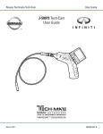
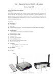
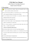
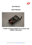
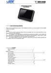
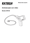
DCS400
USER’S MANUAL
THE SEEKER 400
WIRELESS
VIDEO INSPECTION SYSTEM
Please read this manual carefully and thoroughly before using this product.
CONTENTS
Welcome.....................................................................1
Features .....................................................................1
Packing List ........................................................... 1
Structure ................................................................ 2
Operation .................................................................5
Basic Operation
................................................................ 5
Other Operation and Settings for Monitor ........................ 6
Record Video .....................................................................6
Take Photo ....................................................................... 7
Play Video/Picture ..................................................... 7
Delete Video/Picture
..................................................8
Delete Folder ...............................................................9
Language Setting ........................................................9
Video System Setting ................................................10
Format ........................................................................10
Default Setup ..................................................................10
View Version Information ...........................................11
Frame Rate Setting ...................................................11
Time Stamp Setting ...................................................11
Recording Type
........................................................12
Date/Time Setting .....................................................12
Event Playback ..........................................................12
Specifications ........................................................13
FCC Information ....................................................14
WELCOME
Thanks you for purchasing our data-logging wireless inspection
camera scope. Please read the User’s Manual carefully before
using this product.
The product is designed as a remote inspection device. It can be
used to look into tight spots and beam back real time video to
monitor and record video/take pictures.
Typical applications may include HVAC inspection, automotive inspection, cable routing, automotive/boat/aircraft inspection, etc.
FEATURES
• 3.5" (88.9mm) TFT-LCD Wireless Color Monitor, can be detached
from the unit for remote viewing up to 32.8ft (10m) away
• 3.28ft (1m) Flexible Waterproof (IP67) Obedient Probe
retains configured shape
Standard Length: 3.28ft (1m)
Optional Length: up to 18ft (5.5m)
• 0.67" (17mm) diameter Camera-tipped Probe has built-in
adjustable LED lighting
• Records in Still Photo (JPEG) and Video (AVI), or view it live
• Records up to 3 hours continuously
• NTSC or PAL compatible
• Choices of 10 languages in the menu: English, Spanish, French, German,
Chinese, Portuguese, Italian, Japanese, Dutch, and Russian
PACKING LIST
1
STRUCTURE
INSTALLATION
Please install the batteries, probe and insert the SD card first
before using product, and choose the accessory according
to actual situation.
Please follow the installation steps listed below:
Install Batteries
1. Using a screwdriver, remove screw and cover.
2
2. Remove battery compartment and insert four new “AA”
batteries into the proper slots in the battery compartment.
Proper battery orientation is indicated on the battery
compartment.
3. Reinstall battery compartment and battery cover and screw
as previous.
NOTE! Dry your hands before installation or replacing batteries.
Install the Camera with Flexible Probe
Connect the camera with the probe; make sure the keyed ends
are properly aligned. Once they are aligned, tighten the knurled
knob to hold the connection in place.
Install Accessory
The three accessories include (mirror, hook and magnet), all are
attached to the camera by the same way. Install as follows:
Make sure the stem is placed at side face from the arrow mark,
and tighten to secure the accessories in place.
Install Monitor for Wired Use
The product also supports wired use by connecting the monitor to the
camera.
3
Connect Magnetic Base Stand to the Monitor
The magnetic base stand allows user to stick the monitor on any
metal surface for true hands-free and wireless viewing. Connect
it to the monitor as shown in the following diagram:
Insert SD Card
After the SD card was inserted
successfully into SD card socket,
“ ” icon will appear on the screen;
otherwise, “ ” icon will appear.
Connect USB Cable
Use the USB cable to connect
the monitor to a PC. The USB
online icon appears on the PC.
Open My Computer, and find the
Mobile Disk, the video/picture files
in SD card could be copied/cut/played back.
NOTE! If the video files do not play on the PC normally, please
install the plug-in the enclosed CD-ROM.
Connect Monitor Power
Connect the adapter to the monitor, the red power indicator
will light or the battery capacity icon on LCD of the monitor
will flicker which indicates charging, and will turn off after
a full charge.
Video Output
Insert the video cable into the VIDEO OUT socket of monitor.
4
Insert the other end of the cable into the VIDEO IN jack of a TV or
another monitor. The LCD Monitor will output a high quality video.
OPERATION
Basic Operation
1. Roll the ON/OFF switch to turn ON the camera, and the power
indicator will light up. The switch then acts as a dimmer for the
twin LED’s that surrounds the camera on the camera head and
provides lighting.
F
ON
OF
2. Press and hold on the Power ON/OFF button of the monitor
for 2 seconds, and power indicator will be green, then press
button to select the CH4 (channel 4) and the picture will
display on LCD of the monitor and press
button to
select recording video or take pictures status:
3. Roll the ON/OFF switch of camera for a better image effect.
4. When in use, maneuver the probe into position.
5
TIP! The flexible probe can be bent into a certain shape.
This may help you insert the probe into narrow areas.
5. The accessories can be
used to retrieve small items
such as dropped rings
or screws.
Other Operation and Settings for Monitor
Record Video
1. In the real time monitoring status, press
VIDEO status as follows:
button to enter
2. Press OK button to record as follows:
3. Press OK button again to stop recording.
Notice!
* The Video will be automatically saved as a file every
30 minutes.
* SD card is full when the SD card icon changes to “ ”
6
Take photo
1. In the real time monitoring status, press
photo taking status as follows:
2. Press OK button to take photo.
Notice! when the SD card icon changes to “
card is full.
button to switch to
”it means the SD
Play Video/Picture
1. In the real time monitoring status, press
enter into the following interface:
button to
2. Press
or
button to select folder, then press OK button
to enter into it:
3. For Video:
Press
or
button to select video, then press the OK
button to play as following interface:
7
Pause: press OK button in playing status to pause;
press again to resume;
Fast Forward: press
button in playing status
Fast Backward: press
button in playing status
Stop/Exit: press
button.
For Picture:
Press
or
button to select picture, then press OK button
to display. Press the OK button again to exit.
Delete Video/Picture
1. In the real time monitoring status, press
enter into the following interface:
button once to
2. Press
or
button to select folder, then press OK
button to enter into the following interface:
3. Press
or
button to select file, press and hold
on
button for 2 seconds will enter the following
interface:
8
4. Press
or
button to select YES , then press OK button
will be deleted has been selected by the file; NO will be exit.
Delete Folder
Delete folder is the same as delete file, but make sure the folder
is empty, otherwise it will not delete it and a warning interface
will appear:
How to enter the Setting Mode
In the real time monitoring status, press and hold on
button for about 1 to 2 seconds to enter into the setting
interface as follows:
Language Setting
1. In the setting mode, press
or
button to select
“SYSTEM SETTING” press OK button to enter.
2. Press
or
button to select “Language” press
the OK button to enter into the following interface.
3. Press
or
button to select a suitable language.
4. Press OK button to confirm and exit.
9
Video System Setting
1. In the setting mode, press
or
button to select
“SYSTEM SETTING” press OK button to enter
2. Press
or
button to select “Video System”, press OK
button to enter into the following interface:
3. Press
or
button to select right type, press OK button to
confirm and exit.
Format
1. In the setting mode, press
or
button to select
“SYSTEM SETTING” press OK button to enter.
2. Press
or
button to select “Format” press OK button
to enter into the following interface:
3. Press
or
button to select YES, then press OK button
will erase all data; NO will be exit.
Default Setup
1. In the setting mode, press
or
button to select
“SYSTEM SETTING” press OK button to enter.
10
2. Press
or
button to select “Default Setup” press OK
button to enter into the following interface:
3. Press
or
button to select YES, then press OK button
will restore default; NO will be exit.
View Version Information
1. In the setting mode, press
or
button to select
“SYSTEM SETTING”, then press OK button to enter.
2. Press
or
button to select “ Version”, press OK button
to enter and view the version of product.
Frame Rate Setting
1. In the setting mode, press
or
button to select
“RECORDER SETTING” press OK button to enter.
2. Press
or
button to select “Frame Rate” press OK
button to enter into interface:
3. Press
or
button to select suitable frame rate.
4. Press OK button to confirm and exit.
Time Stamp Setting
1. In the setting mode, press
or
button to select
“RECORDER SETTING” press the OK button to enter.
2. Press
or
button to select “Time Stamp” press OK
button to enter into the following interface:
11
3. Press
or
button to select “Off” or “On” then press the
OK button to confirm and exit.
Recording Type
1. In the setting mode, press
or
button to select
“RECORDER SETTING” press OK button to enter.
2. Press
or
button to select “Recording Type” press the
OK button to enter into the following interface:
3. Press
or
button to select “STILL VIDEO” then press
the OK button to confirm and exit.
Date/Time Setting
1. In the setting mode, press
or
button to select
“Date/Time” then press the OK button to enter into the
following interface:
2. Press the OK button to select Date or Time; press
or
button to modify; press
button to confirm and exit.
Event Playback
1. In the setting mode, press
or
button to select
“EVENT PLAYBACK” then press the OK button to enter.
2. Other operations see: “Play Video/Picture”,
“Delete Video/Picture”, “Delete Folder” section.
12
SPECIFICATIONS
Camera
Imaging Sensor
Total Pixels
Horizontal View Angle
Transmission Frequency
Minimum Illumination
Modulation Type
Bandwidth
Power Source
Unobstructed Effective Range
Waterproof Capacity
Dimensions (WxDxH)
Weight (about)
CMOS
704 x 576 (PAL)/712 x 486 (NTSC)
50°
2468MHz
0 Lux
FM
18MHz
4 “AA” batteries
32.8" (10m)
IP67 (only for probe head)
7.3" x 5.7" x 1.6" (186 x 145 x 41mm)
(Excluding Flexible Tube)
19oz (530g)
Monitor
LCD Screen Type
Effective Pixels
Video System
Transmission Frequency
Exterior Supply Voltage
Consumption Current (Max.)
Charge Time
Work Time
Picture/Video Pixels
Video Size
Frame Rate
Video Output Level
Receiving Sensitivity
Dimensions (W x D x H)
Weight (About)
Operating Temperature
Operating Humidity
3.5" TFT-LCD
320 (R.G.B.) x 240
PAL/NTSC
2414MHz,2432MHz,
2450MHz,2468MHz
5VDC
500mA
3 hours
2 hours
640 x 480
27M byte/minute
30 frame/second
0.9-1.3VP-P@75ohm
≤-85dBm
4" x 2.8" x 1" (100 x 70 x 25mm)
5oz (140g)
14° to 122°F (-10° to 50°C)
15%~85%RH
* Actual transmission range may vary according to the weather, location,
interference and building construction.
* All the specifications are subject to minor change without prior notice.
13
FCC INFORMATION
This device complies with part 15 of the FCC Rules. Operation
is subject to the following two conditions: (1) this device may
not cause harmful interference. (2) this device must accept any
interference received, including interference that may cause
undesired operation. Changes or modifications not expressly
approved by the party responsible for compliance could void
the user’s authority to operate the equipment.
CAUTIONS!
• The apparatus shall not be exposed to dripping or splashing
and that no objects filled with liquids, such as vases, shall be
placed on the apparatus. Do not expose instrument to moisture.
• Turn off the Camera/Monitor if the system is not in use.
• The adapter is used as the disconnect device from the mains.
The adapter shall remain readily operable.
• The Camera/Monitor can only be completely disconnected from
the mains by unplugging the adapter.
• Do not cut the DC power cable of the apparatus to fit with
another power source.
• Attention should be paid to dispose batteries in environmentallyfriendly ways.
• Remove the batteries when cleaning the unit.
• Remove the batteries before storing the unit for a long time.
• When necessary, replace all four batteries in this unit with new ones.
• Use only the size and type of battery specified.
• Be sure to install the battery with the correct polarity as
indicated in the battery compartment.
EU Environmental Protection
Waste electrical products should not be
disposed of with household waste.
Please recycle where facilities exist.
Check with your Local Authority or
retailer for recycling advice.
14
NOTES
GENERAL TOOLS & INSTRUMENTS™
80 White Street
New York, NY 10013-3567
PHONE (212) 431-6100
FAX (212) 431-6499
TOLL FREE (800) 697-8665
e-mail: [email protected]
www.generaltools.com
DCS400 User’s Manual
Specifications subject to change without notice
©2009 GENERAL TOOLS & INSTRUMENTS™
NOTICE - WE ARE NOT RESPONSIBLE
FOR TYPOGRAPHICAL ERRORS.
MAN#DCS400 7/09