1
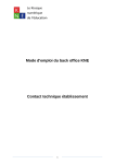
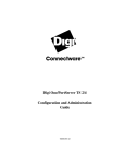
SUPER PSG VST SN76489 SMS www.alyjameslab.com USER MANUAL 1.0 BY Aly James ©2013-2014 ALYJAMESLAB TABLE OF CONTENTS SUPER PSG VST ..................................................................................................................... 1 INTRODUCTION............................................................................................................................. 3 INSTALLATION............................................................................................................................... 6 CONTROL PANELS ......................................................................................................................... 9 THE SN76489 PSG CHIP ................................................................................................................11 MAIN CONTROLS..........................................................................................................................15 SETTINGS.....................................................................................................................................17 AMP GENERATOR.........................................................................................................................19 PITCH GENERATOR.......................................................................................................................22 ARPEGGIATOR .............................................................................................................................25 SPECIAL - TIMERS & AY-EG ............................................................................................................27 TABLES ........................................................................................................................................35 NOISE LFSR CHANNEL ...................................................................................................................37 PCM SAMPLES .............................................................................................................................39 PRESETS IMPORT / EXPORT...........................................................................................................41 MIDI AUTOMATION......................................................................................................................42 HARDWARE .................................................................................................................................44 HIDDEN SECRETS..........................................................................................................................45 LINKS...........................................................................................................................................48 DISCLAIMER & LICENCE AGREEMENT ............................................................................................50 INTRODUCTION My name is Aly James; French steam funky musician, composer and creator of strange musical DIY devices and software. Based on the relatively good success of my Sega Megadrive/Genesis VSTi, FMDrive, I was planning to make an entirely separate VST dedicating to the second Sound Chip aka PSG, SN76489 also known as DCSG. The SN76489 was also the main sound chip of the Sega Master System console and the second sound chip of the Sega Megadrive/Genesis. It was originally integrated in my FMDrive VST but I have decided to give it its own dedicated host with lots of features and controls. A very similar chip was also the AY3 8910 (ZX SPECTRUM, MSX…) that lacks a real independent frequency control of the noise channel but adds a hardware envelope that can be used to produce waveforms instead. It is nice to notice that his looping envelope feature will also end in the YM2612 as the SSG envelope part… The Japanese Master System also featured a limited FM module via the YM2413 chip. This is not emulated in SPSG VST because we have YM2612 FMDrive VST that can do way better on the FM side! ________________________________________________________________________________ Like said previously, I am not very used to tracker music making or MML programming, which is why I needed an SN76489 VST Instrument. I also needed a way to control the real hardware via MIDI. I learn a lot from documentations and hardware testing and also from all the nice people who documented the SN76489 on the web. You know who you are. It started out as a simple but accurate SN76489 emulator then slowly turned into a complex featured synth. I wanted to make any sound possible with the chip included some of the features the AY3 8910 had and also circuit bent the technology used to produce the noise channel. It turns out to be quite nice so I decided to make it public in exchange for a small donation for the large amount of work I put into this. The goal was on one hand to make a bit perfect SN76489 emulation with control over the master clock frequency because as you will learn latter in this manual, the frequency range that can be played by the chip highly depends on the master clock… On the other hand, 3 square wave generators and 1 noise/periodic generator can be pretty limited if used in a basic way…, which is why I have experimented what could be done on the real chip to produce extended modulation options. In the end I have implemented those experiments results into the VST an also added the AY3 8910 hardware envelope part and a nice circuit bending option for the noise generator. All and all the SUPER PSG EXTENDED emulation turns out to be a fantastic 8bit synth suitable for chip music and Sega nostalgic pleasure and also a powerful tool for modern music production. This emulation uses a totally new core with band limited waveforms (excepted for the Timer waveforms which are raw). The product has been assembled through the SYNTHEDIT engine using the very last version, custom C++ coding and some third party licensed code. It may be ported to OSX at some point in the future. ________________________________________________________________________________ Thanks to all the nice people that started to use SPSG and support my projects. A special thanks to SMS.org, Maxim and TmEE, also Sebastian Tomczak who designed the SMSN,GENMDM midi hardware interface and provide great sources of inspiration and to Yuzo Koshiro and Alberto Gonzales “Mc Alby” for their music and support on SPSG. Full Credits & Thanks can be accessed on the SPSG GUI panel. Mainly, SPSG can act either as the SN76489AN CH1, 2, 3 or CH4 Noise channel. It can be either polyphonic (copy the settings to 3 voices) or mono like the real chip and can act as 3 SN76489 Tone channels at once with the same patch when in poly mode... The Noise channel is always mono and can be controlled separately. PCM samples can also be played and controlled separately through the Tone volume register. In addition to the above, software Timers are provided to produce some unusual Tone modulation by writing to the volume register and an emulated AY3 8910 Sound Chip Envelope generator part is available to produce some classic and not so classic “Buzzers” type of sound. However you have to load 3 instances of the VST to have 3 really independent Tone channels. This particular implementation allows getting over the original channels limit if ones need it. It also simplifies automation control as there are a lot of parameters for a single channel. It was unnecessary to implement an internal echo feature as every single DAW features a Stereo delay that can be set to produce a classic 2 or 3 PSG channel delay easily. A delay greatly enhances some PSG sounds particularly if you use the chip as a single instrument among a complex composition, just remember to limit the polyphony to 3 for accuracy. Basic MIDI implementation: MIDI IN: SPSG can receive any MIDI CH as main source for notes and key on/off. Independent MIDI IN can be set for TONE, NOISE and PCM source control. MIDI OUT: SPSG can send MIDI CC & PITCHBEND data over any MIDI channels. For example if you assign MIDI CC#11 to the volume amplitude register of the Tone channel, when it is changed, SPSG will also send CC#11 DATA over the chosen MIDI channel and also PITCHBEND DATA for ARP or PITCH ENVELOPE (Pitch bend output resolution is 48 semitones) allowing to send the amplitude envelope to the hardware or for example to make a MIDI track suitable for VGM conversion. INSTALLATION COMPATIBILITY SPSG is a Windows 32Bit VST Instrument for use with MIDI capable DAWs. RUN on 32/64 Bit Systems. If you want to use it with a 64bit DAW you can use JBridge or internal DAW Bridge. INSTALL VST 1. Decompress the downloaded archive file 2. Copy the entire Folder SPSG to your VST PLUGINS folder 3. Load it in your DAW INSTALL STANDALONE 1. Decompress the downloaded archive file 2. Copy the entire Folder SPSG_STANDALONE where you want 3. Simply RUN SPSG.exe State of SPSG current features WIN 32 VST runs on 32/64Bit Systems and it is multicore compatible HIGH QUALITY GUI (Different panels for controls etc...) INSTANT UPDATE FOR ALL CONTROLS FULL MIDI AUTOMATION With midi learn (right click to assign MIDI) 3 CHANNELS POLY & MONO MODE With Portamento Control DIRECT CHIP OUTPUT OR CONSOLE FILTERING Sega Master System or Sega Megadrive/Genesis SN76489AN classic features SUPPORT ANY CLOCK RATE From 1 MHz to 4 MHz like the real chip 1-64 STEPS Amplitude Envelope Generator 64 steps persistent memory, up to 300 Hz, synced or independent speed rate, loop, ping pong and release step 1-64 STEPS Pitch Envelope Generator 64 steps persistent memory, up to 300 Hz, synced or independent speed rate, loop, ping pong and delay LFO VIBRATO For quick expression INTERNAL ARPEGGIATOR Programmable or live controlled via MIDI Input MEMORY SLOTS & TABLES 8 memory slots per envelope, arpeggiator and advanced waveforms than can be internally sequenced at any available clock speed (can be used as a wave-table for software waveforms...) PCM & PWM (4 slots to load any PCM WAV files/ auto converted to mono) that will be played to the SN76489 volume register on one or three channels at the time. SN76489AN extended features AY3 8910 ENVELOPE GENERATOR Optional AY3-8910 emulated Envelope Generator, Buzzers, Sync Buzz... A feature that was only available on the AY and YM2149 chip (ZX spectrum, MSX, Atari ST…) Z80 SOFTWARE TIMER Z80 Timer pulse width modulation, (SID) Sound or custom waveforms, can also synced the AY3 8910 Hardware Envelope Generator for sync type effect. NOISE CHANNEL CIRCUIT BENDING the LFSR generator is tweak-able in real-time (tapped bits mask and feedback bit), from the original fixed 16-bit configuration of the Sega Master System/Genesis to anything in between…which basically gives you the ability to reach some different sound chips type of noise or mess it up in a unique way, all of that in real-time. MIDI OUT FOR AMPLITUDE & PITCH LOAD & SAVE FULL PATCH & BANKS in FXB/FXP CONTROLS A REAL SN76489 CHIP or MASTER SYSTEM/MEGADRIVE HARDWARE VIA MIDI (For Master system or Megadrive, Needed Little Scale SMSN/GENMDM Midi Device) An ATMEGA MIDI controlled SN76489 device can be easily built if needed (open source code is available on request) CONTROL PANELS Overview SPSG GUI INTERFACE stores the different parameters on different panels. The main sliders TONE, NOISE & PCM sets the global volume multiplier for each channel. SYNC is the master envelope clock in BPM that is affected to an envelope, if set (see ENVELOPES). LFO set the vibrato speed and PMS the amount of pitch modulation (only affect TONE channel). The SETTINGS button opens the main settings, MIDI configuration and circuit bending menu (see SETTINGS) Each main channel types (TONE, NOISE or PCM) can be selected at the bottom. Once in, they contain different features/panels that can be selected at the top and activated/deactivated on the bottom right of the GUI. Access to the TABLE feature (see TABLES), if available, is done by clicking on the SEQ TABLE button. These are sections are for: TONE CHANNEL: AMP Volume envelope PITCH Frequency, Pitch envelope ARP Arpeggiator SPECIAL Advanced controls, Transpose, Fine tune, Z80 Timer, AY3 8910 Hardware envelope generator SEQ TABLE Enter in TABLE mode for the selected section, where memory slots can be sequenced (see TABLES). NOISE CHANNEL: AMP Volume envelope PITCH Frequency, Pitch envelope LFSR Set the LFSR configuration, White Noise, Periodic or customs ones, Frequency control mode from FIXED or KEY (uses MIDI NOTE frequency) SEQ TABLE Enter in TABLE mode for the selected section, where memory slots can be sequenced (see TABLES). PCM CHANNEL: PCM Channel as only one main panel that let you import .WAV samples and control play modes. (See PCM) Right click on a knob, button or slider will open a midi learn assign menu. Ctrl click + move allow fine tuning. THE SN76489 PSG CHIP The SN76489 (N or AN) Digital Complex Sound Generator (DCSG) is a TTL-compatible Programmable Sound Generator chip from Texas Instruments, a custom version was included into the Sega VDP chip. It contains three square wave tone generators and one white noise generator, each of which can produce sounds at various frequencies and sixteen different volume levels. It has been used in lots of arcade systems and consoles and was generally clocked at 3.5 MHz (NTSC, PAL) witch limited the bass response available (the chip can be clocked between 1 to 4 MHz). The lower the clock, the lower the frequencies available but also there will be high frequencies precision lost. The way these sound chips calculated the frequency was usually by dividing the master clock which results in a lack of precision on higher frequencies. These limitations are a noticeable part of the characteristic sound of the PSG when you use it in conjunction with other sound source such as FM. Because the chip will never be perfectly in tune, this gives movement in sound… This graphic shows the SN76489 frequencies available in regard to a linear frequency sweep. Frequencies are set via a 10-bit register (1024 values) and counted down until they reach 0, at which point the output waveform for that channel will toggle (0 or 1) and the counter will be reloaded. This counter usually runs at 3.5MHz (Master System/Genesis), the same clock as the Z80 processor. For reference: the 10-bit FNUMBER can be calculated this way: 𝑭𝑵𝑼𝑴𝑩𝑬𝑹 𝟏𝟎𝑩𝑰𝑻 = 𝑪𝑳𝑶𝑪𝑲𝑯𝒛 𝑭𝑹𝑸𝑯𝒛 ∗ 𝟑𝟐 The lowest possible frequency for a fixed clock can be calculated this way: 𝑭𝑹𝑸 𝑯𝒛 The frequency range VS master clock speed. = 𝑪𝑳𝑶𝑪𝑲 𝑯𝒛 𝟏𝟎𝟐𝟒 ∗ 𝟑𝟐 DCSG CLOCK (Hz) DCSG FREQUENCY RANGE (Hz) 4000000 122.070312 ---------------------------------------------------------------------------- 125000 3579545 (NTSC) 109.239044 ------------------------------------------------------------------- 111860.78125 3546893 (PAL) 108.242584 -------------------------------------------------------------------- 110840.40625 2000000 61.0351562 ------------------------------------------------------------------------------- 62500 1000000 30.517578 -------------------------------------------------------------------------------- 31250 The noise channel can be either WHITE noise or PERIODIC, as for the tone channels the output bit is toggled between 0 and 1 but this time it is sent to a 16-bit* “Linear Feedback Shift Register” (LFSR) which can generate pseudo random noise with a periodicity up to 65535 (2^16 -1, excluding all 0 state) or act as a divider. In the case of the Sega Master System PSG the periodicity for the white noise is 57337** and 16 for the “periodic” noise . The frequency of the noise is either fixed at CLOCK divided by (512, 1024 or 2048) or controlled by the frequency of the third tone channel. Doing this will also disable the third tone channel… The so called periodic noise will then output a 1/16 duty cycle pulse wave which is 4 octaves down compared to the tone channels, even if the same frequency is set. This is mainly because it takes 16 more time for the output bit to be toggled than on a normal tone channel, resulting in the actual frequency being FRQ/16. The frequency resolution of higher notes being limited this also results in a slight detuning between periodic and tone output frequency although they have the same frequency setting. * On the SEGA VDP integrated version of the chip. ** It means that it will take 57337 different 16-bit patterns before the LFSR comes back to its initial 0x8000 (1000000000000000) state. In addition, several advanced techniques can be used to produce interesting modulation, for example you can use the Z80 processor of the Sega Master System to write MAX volume, MIN volume to the volume register of a channel, if you do this at audio rate, this will produce another square wave… If you set this modulation at nearly the same frequency than the actual tone, this will produce a change in time of the pulse width and the more detuned the more the beating effect (you can also output more complex waveforms this way). PCM samples can also be played in a limited way on the volume register by setting the frequency to 0x000 to produce a DC modulated by the sample data. You can either use PCM or PWM method. Mixing the two without setting all 0 frequencies can lead to interesting creative results. The volume setting is then used as a 4-bit DAC. All three tone channels can be used together to get maximum volume if needed. The logarithmic nature of the PSG volume versus linear PCM data will also give the samples a characteristic sound if you use Pulse Code Modulation method (PCM). Data sample can be rescaled before being outputted to the PSG to maintain the natural linearity of the original data, however with particular settings; the output of not rescaled data sample can act as a transient enhancer of some sort. PWM method is basically a raw 1-bit (MAX volume or MIN volume) conversion of the sample data and will therefore be louder than PCM method. MAIN CONTROLS Each channel is selectable to control or edit via the 3 select buttons, CH TONE, CH NOISE and CH PCM. Setting LFO to minimum also disable vibrato generator saving system memory resources when not in use. Common Parameters: • TONE: Tone channel general volume multiplier (can also be MIDI assigned to an external CC# with AMP envelope deactivated to play data from a VGM MIDI transcoded track). • NOISE: Noise channel general volume multiplier (can also be MIDI assigned to an external CC# with AMP envelope deactivated to play data from a VGM MIDI transcoded track). • PCM: PCM data general volume multiplier. • SYNC: Is a value in BMP that serves as a master clock for any SYNCED AMP, PITCH and ARP envelopes. As you will see later each envelope can be clocked to this SYNC BPM or can have an independent clock source… • LFO: the frequency of the LFO Vibrato ranges from 3.98Hz to 72.2Hz like on the YM2612. (Vibrato applies only on TONE channels). Set in to minimum to disable when not in use, this will also saves CPU. • PMS: Pitch Modulation Sensitivity (vibrato applies only on TONE channels). Note that as the pitch resolution of the SN76489 sound chip will decrease the higher the notes so will be the resolution of the vibrato. This means that a small modulation setting cannot be heard any more on high octave. PMS EFFECT ON PITCH 0 1 2 3 4 5 6 7 No effect Displacement of ± 3.4%* Displacement of ± 6.7%* Displacement of ± 10%* Displacement of ± 14%* Displacement of ± 20%* Displacement of ± 40%* Displacement of ± 80%* * Percent of a halftone. • SETTINGS: Access the main settings of the VST, like MIDI IN, OUT channels configuration, Sound chip output filtering, Pitch Bend Range, Mono, Poly and Portamento… (See SETTINGS). • • • CH TONE: Enters the TONE channel panel CH NOISE: Enters the NOISE channel panel CH PCM: Enters the PCM channel panel Last but not least, an oscilloscope display lets you see the changes in the waveform. SETTINGS The Global settings panel lets you assign the MIDI IN channels that will control each sound source, TONE, NOISE & PCM. This is where you can set the MASTER CLOCK rate of the SN76489 chip. You can choose between 4 built-in settings, NTSC, PAL, 1MHz or 4MHz. Of course you can set anything in between and every calculation of the ship will accurately depend on that clock. You can also choose the output filtering of the SN76489 between Sega Master System console, Sega Genesis/Megadrive and the direct unfiltered output of the chip. This is also here that you can set the Pitch Bend Range and the mono Portamento affect for TONE & NOISE channels. You can also choose if you play only one TONE channel (Mono) or the 3 at the time which will share the same envelopes and settings (POLY). The Last part will set the configuration for MIDI OUT data that SPSG will be sending (see MIDI AUTOMATION). Settings Parameters: • MASTER CLOCK: Select NTSC, PAL, 1Mhz or 4Mhz. You can also type in any value between 1 MHz and 4 MHz (1000000 and 4000000). • VOICE CONTROL: Choose the MIDI channel that the voice will respond to. Note that you can assign the same MIDI channel to many sources, for example to control noise & tone at the same time. The configuration is saved with patches. • TONE POLY STATE: Switch between MONO, plays only one tone channel or POLY to play the 3 tone channels at the time with the same envelopes and settings. • ENVELOPE RETRIGGER: When ON, each new key will retrigger envelopes from the beginning, sometimes it is preferable to retrigger only on non-legato notes so this can be OFF. • MONO CONTROL: PT is the Portamento setting and PBR is the pitch bend range in semitones. • SN76489 FILTERING: Choose between SMS, GENESIS or direct non buffered, unfiltered chip output. • NOISE LFSR STATE: Is just a reminder of the actual state of the LFSR (noise channel). • MIDI OUT: ENABLE the MIDI OUT if needed or leave it to DISABLED (see MIDI AUTOMATION). AMP GENERATOR Simply draw the envelope with the mouse, click on a particular step to select it. Any numbered parameters can also be typed directly via keyboard. HINT: You can randomize any envelope by Left clicking + CTRL + MAJ. THIS SWITCH WILL ACTIVATE OR DEACTIVATE THE ENVELOPE GENERATOR Volume Envelopes AMP ENVELOPE GENERATOR FOR THE TONE & NOISE CHANNEL AS THE SAME BEHAVIOR The SN76489 can produce 16 discrete levels, internally set from 15 (MAX attenuation) to 0 (FULL VOLUME) The sound starts when the key is depressed, a process called ‘key on’. The sound will then passes to each stages/steps of the envelope and sustain on the last step. The more the steps and speed the less stepper the resulting envelope will be. SPSG can reach near 300 Hz speed (ticks per second) however keep in mind that most of the sound drivers used in past games rarely outputs more than 60 Hz…even if the sound chip itself can. These are the main parameters of an AMP envelope: • STEPS: Is the number of steps that will be played, can be anything between 1 to 64 steps. The number of steps played can be automated in real time and will not discard the steps previously set if you reduce the number dynamically. • SPEED: Is a clock speed multiplier it will multiply the AMP CLOCK by the amount (ex: CLOCK= 120, SPEED = 2, will play each step at 120*2 = 240 BPM). • SLOTS: There are 8 MEMORY SLOTS available; these are memory storage for the 64 envelope steps levels, you can switch between them via automation at any time for complex envelopes and even sequence them with TABLES (see TABLES). You can also COPY a MEMORY SLOT to another via the COPY FROM button. • CLOCK: This is the main CLOCK of the envelope in BPM; it is the principal parameter to calculate the envelope step final speed. If you click on the SYNC button the CLOCK value will turn green and will be controlled by the main SYNC value (SYNC slider on the main panel). • LOOP: Is the number of steps that has to be played before activating the LOOP mode. For example let’s say we have set a 16 steps envelope then if you set the LOOP parameter to 32, the result will be: >> PLAY the 16 STEPS>>WAIT for 16 STEPS>>PLAY AGAIN from STEP 1 and so on. Basically set it to 2 to LOOP endlessly. • RSTEP: Is a special feature that when set above 0, will apply an automated high resolution release curve to the final step. The higher the setting, the longer the release tail will be. This is also useful for quick simple decaying envelope, just set the envelope to only 1 step and activate RSTEP. (Note that the last step has to be reached before applying). If a release step is activated the display will highlight a full bar for the last step. • SYNC: When this button is ON (red) the CLOCK BPM value will turn green and will be controlled by the main SYNC value (SYNC slider on the main panel). It is useful to sync AMP, PITCH etc… when in need, to control the main speed with only one main SYNC slider. • GATE / RELEASE: When in GATE mode, the sound will immediately stops and be set to minimum volume when a key is released, regardless of what value the current step volume was on. This is the most common setting. When in RELEASE mode, the sound will play all the steps in the envelope even if a key is released except if it encounters a 0 volume STEP, in this case it will stops at the first step that as a 0 volume value. Be careful with this release setting as it will maintain a voice awake an can produce a sound when you load a project, this should only be used to record and set back to GATE mode before saving for safer usage. • NORMAL / REVERSE: Only if the LOOP parameter is activated a REVERSE setting will play the envelope from END STEP to START STEP once the last step is reached. PITCH GENERATOR Simply draw the envelope with the mouse, click on a particular step to select it (draw or single). Any numbered parameters can also be typed directly via keyboard. HINT: You can randomize any envelope by Left clicking + CTRL + MAJ. THIS SWITCH WILL ACTIVATE OR DEACTIVATE THE ENVELOPE GENERATOR Pitch Envelopes PITCH ENVELOPE GENERATOR FOR THE TONE & NOISE CHANNEL AS THE SAME BEHAVIOR REMINDER: The SN76489 can produce 1024 discrete pitch The sound starts when the key is depressed, a process called ‘key on’. The sound will then passes to each stages/steps of the envelope and sustain on the last step. The more the steps and speed the less stepper the resulting envelope will be. SPSG can reach near 300 Hz speed (ticks per second) however keep in mind that most of the sound drivers used in past games rarely outputs more than 60 Hz…even if the sound chip itself can. These are the main parameters of the PITCH envelope: • STEPS: Is the number of steps that will be played, can be anything between 1 to 64 steps. The number of steps played can be automated in real time and will not discard the steps previously set if you reduce the number dynamically. • SPEED: Is a clock speed multiplier it will multiply the PITCH CLOCK by the amount (ex: CLOCK= 120, SPEED = 2, will play each step at 120*2 = 240 BPM). • SLOTS: There are 8 MEMORY SLOTS available; these are memory storage for the 64 envelope steps levels, you can switch between them via automation at any time for complex envelopes and even sequence them with TABLES (see TABLES). You can also COPY a MEMORY SLOT to another via the COPY FROM button. • CLOCK: This is the main CLOCK of the envelope in BPM; it is the principal parameter to calculate the envelope step final speed. If you click on the SYNC button the CLOCK value will turn green and will be controlled by the main SYNC value (SYNC slider on the main panel). • LOOP: Is the number of steps that has to be played before activating the LOOP mode. For example let’s say we have set a 16 steps envelope then if you set the LOOP parameter to 32, the result will be: >> PLAY the 16 STEPS>>WAIT for 16 STEPS>>PLAY AGAIN from STEP 1 and so on. Basically set it to 2 to LOOP endlessly. • DELAY: Will wait x DELAY amount of steps before triggering the pitch envelope, this is very useful when you don’t want to apply a pitch modulation immediately after a key on. • DISPLAY MAX & MIN: The pitch envelope ranges from -4 Octaves down to +4 Octaves up, It is a value in semitones (where + 12 = 1 Octave) you can set the MAX and MIN value of the envelope and the display will scale accordingly. Note that if a previous step was out of the new range, it will not be rescaled, only new entered step value will. • SCALE: Will scale the envelope to the nearest integer semitone value. As The SN76489 got 1024 possible frequency values we can simplify this linearly and say that we can adjust the pitch to 1/8 of a semitone, so the chip can recognize 0.25 (1/8 of a semitone). This is actually not totally true because the resolution increases for low notes and decrease for high pitched ones… However you can enter non integer values in the SELECTED STEP PITCH text box and when you draw the pitch envelope the remainder part is also kept. This means that you cannot draw precise semitones easily (in draw mode) if needed and that is what the SCALE function is used for. It will scale the envelope to the nearest integer semitone value. This is useful the make more complex arpeggios, glissandos and runs pretty quickly! (Single mode is more precise). This not particularly needed for non-musical pitch effects. • SELECTED STEP PITCH: It is a text box where you can type the desired semitone value for the selected step. First select the desired step by moving or clicking it then enter the value in the text box, click anywhere to leave. (You can also enter non integer values in the limit of -48 to +48). • DRAW & SINGLE Edit Mode: The TONE PITCH envelope features a special edit function, Draw or Single, DRAW will let you draw a full shape in one quick movement, SINGLE will let you move only the selected step then, allows precise editing with click + MAJ and for ultraprecise editing, click + CTRL. (Also the step will not be changed when you click on it as in draw mode; this is useful to check what value a particular step is.) ARPEGGIATOR This can be a quick programmable 3 notes arpeggiator or a complex MIDI driven one. These 2 behavior modes, PROGRAM or MIDI, can be selected by clicking on the red centered screen display. Any numbered parameters can also be typed directly via keyboard. THIS SWITCH WILL ACTIVATE OR DEACTIVATE THE ARPEGGIATOR Arp Play Modes SPSG can reach near 300 Hz speed (ticks per second) however keep in mind that most of the sound drivers used in past games rarely outputs more than 60 Hz…even if the sound chip itself can. The arpeggiator can behave in two distinct ways, depending on the setting: PROGRAM MODE: In PROGRAM mode, you set the desired 3 notes via the 3 red sliders or by selecting the value directly; the arpeggiator will always begin on NOTE 1. MIDI MODE: In MIDI mode, the arpeggiator will process the notes that you play according to the MIDI MODE OCTAVE & MIDI DIRECTION settings, regardless of the STEPS setting. This mode is more adapted to complex live playing and produces great results in term of nonlinear arpeggios. These are the main parameters of the ARPEGGIATOR: • STEPS: Is the number of steps that will be played, can be anything between 1 to 64 steps. The number of steps played can be automated in real time. As the arpeggiator in PROGRAM mode as only 3 steps, the STEPS parameter is used for the amount of time you want it to be on. Depending on the STEPS setting, the last note will not necessary be the First or the Last… An easy way to calculate for the last step being the first is that the STEPS must be equal to a multiple of 3 and add 1. • SPEED: Is a clock speed multiplier it will multiply the ARP CLOCK by the amount (ex: CLOCK= 120, SPEED = 2, will play each step at 120*2 = 240 BPM). • SLOTS: There are 8 MEMORY SLOTS available; these are memory storage for the 3 ARP notes, you can switch between them via automation at any time for complex evolving arpeggios and even sequence them with TABLES (see TABLES). You can also COPY a MEMORY SLOT to another via the COPY FROM button. • CLOCK: This is the main CLOCK of the arpeggiator in BPM; it is the principal parameter to calculate the arpeggiator step final speed. If you click on the SYNC button the CLOCK value will turn green and will be controlled by the main SYNC value (SYNC slider on the main panel). • LOOP: Is the number of steps that has to be played before activating the LOOP mode. For example let’s say we have set a 15 steps arpeggiator then if you set the LOOP parameter to 32, the result will be: >> PLAY the 15 STEPS>>WAIT for 16 STEPS>>PLAY AGAIN from STEP 1 and so on. As the loop mode is a power of 2 some STEPS settings can ends on a different notes on each new pass, this can be used creatively. Basically set it to 2 to LOOP endlessly. • DELAY: Will wait x DELAY amount of steps before triggering the arpeggiator, this is very useful when you don’t want to apply the arpeggiator immediately after a key on. These are the main parameters of the MIDI MODE: • MIDI MODE OCTAVE: X1 will basically cycles the entered notes, X2 will push it one octave, X2 two Octaves and so on. • MIDI DIRECTION: Will set the direction of the arpeggio, UP, DOWN, UPDOWN & also RANDOM. Set it to OFF will disable the MIDI ARPEGGIATOR. SPECIAL - TIMERS & AY-EG This panel features some complex modulation routines using software TIMER interrupts, the AY3 8910 emulated envelope generator or both. Any numbered parameters can also be typed directly via keyboard. HINT: You can randomize custom timer waveforms by Left clicking + CTRL + MAJ. THE BUTTONS ON THE LEFT WILL ACTIVATE THE DIFFERENT MODULATORS AVAILABLE. This important to understand that the TIMER interrupt routine and the HARDWARE envelope can generate both very low frequencies while the 10-bit frequency counter of the natural TONE channel is more limited in regard of the MASTER CLOCK frequency. The result is that when you use TIMER or HARDWARE to modulate the TONE, you will hear that the TONE frequency will stick to its lowest limit according to the chip MASTER CLOCK while the TIMER & the HARDWARE still outputs the played frequency. You can minimize this effect simply by lowering the MASTER CLOCK (lowest possible clock of 1000000 Hz will have a limit of 30.52 Hz). Z80 Timer The SN76489 can produce 16 discrete levels, internally set from 15 (MAX attenuation) to 0 (FULL VOLUME) If you use a TIMER Interrupt to write a routine to the volume register at audio rate you will obtain another raw waveform, this can be used to play another software voice or to modulate the actual TONE. A common technique on these basic sound chips is to create a pulse width modulation on the TONE channel even if the chip can only generate a fixed 50/50 duty cycle square wave. This technique, commonly used on the ATARI ST scene, was named the SID sound or SID voice as it mimics the type of moving lead sound the C64 sound-chip (SID 6581) was able to produce. Another possibility is to use a Timer Interrupt to trigger a little 4-bit sample of a 1 cycle waveform; this will produce a completely new waveform to use alone or as a “SID” modulator. The way the frequency for the Timer Interrupt is calculated allows for an acceptable precision. A possible use with Z80 is the Horizontal Blank Interrupt. As you will see for the emulated AY3 8910 HARD envelope generator a frequency ratio conversion is available to adjust the pitch. AY3 8910 Hardware Envelope The AY3-8910 PSG has a built in basic envelope generator that can replace any written amplitude data by the output of the envelope. The start en end value is always MAX or MIN. 4 Particulars envelope types are interesting because they will automatically loop; this is how when the envelope period reaches the audio range it can output a SAW, RAMP or TRIANGLE type of waveform also known as “BUZZERS”. The AY Envelope had 16 steps versus 32 for the YM2149. The envelope period is calculated by dividing the MASTER CLOCK by 256*EP (16-bit Envelope period). The AY was usually clocked at 2 MHz; this calculation allows a relatively good resolution for slow period as low as 0.1 Hz but will greatly reduce fast period resolution and will top at 7812.5 Hz. This is why it was only mainly used for bass lines has it will be out of tune pretty quickly on higher octaves. Fig.1 shows the looping shapes in red are the looping ones, and the ones that you can set in SPSG. Fig.3 shows the envelope possible levels. Emulating the envelope generator as to take in account that the Hardware envelope counter is 16-bit versus the SN76489 frequency is 10-bit. So you have to binary left shift by 3 (*8) the envelope period to obtain the desired frequency on the PSG. Doing the opposite will result in precision loss and will not produce perfect pitch synchronization. This technique as its counterpart because it will reduce the high notes resolution of the PSG, this will also apply the same precision loss on high pitched notes the hardware envelope has. SPSG internally uses a FREQUENCY RATIO from 1:1 that tries to apply the PSG frequency to the hardware frequency with precision loss, to 8:1 that will produce a more similar pitch. A liberty has also been taken on the original design to allow the hardware frequency to cover the DCSG range. This graphic shows the differences between Tone and Hardware frequency resolution at 1:1 ratio and also demonstrate that the hardware can produce very low frequencies that the SN76489 alone cannot. LOSS OF PITCH DEFINITION LIMIT OF SN76489 LOWEST FREQUENCY . The frequency of the tone being 10-bit versus 12-bit for the AY tone you will need to lower the Master CLOCK frequency of the SN76489 chip to obtain possible modulation on lower octaves. You can also disable the tone and only use the HARDWARE generated waveform by forcing the tone period to ZERO. You can then use the hardware waveform alone as a saw or triangle bass tone and, as you will see in the features details, also use the TIMER to synchronize the hardware envelope. Because each time the internal Hardware register is rewritten by the TIMER it will restart the envelope, it allows sync type effects also known as “SYNC BUZZERS” The use of different frequencies between TONE, TIMER & HARWARE can produce a lots of effects some harsh and some more mellow, this is a great way to experiment and this is why you have a Transposition and fine tune panel available. Main Special Controls • 3 WAY BUTTONS SELECTOR: These buttons let you switch between normal TONE output with no modulation, TIMER or HARDWARE modulation. IMPORTANT when HARD is selected it will completely disables the AMP envelope; any setting will have no more effect on the volume. • PM: When ON, this button will send the ARP & PITCH ENVELOPE modulation to the TIMER & HARDWARE. • TONE PERIOD: Will usually be set to “KEY” that means that the TONE channel frequency is controlled by the notes you play. However if you want to only hear the Timer waveform or the Hardware waveform without Tone modulation you have to force the TONE frequency to 0. The setting “ZERO” will then set the Tone frequency to 0 disabling the TONE output. (Note that this can also be used to only modulate DC with the AMP envelope generator…) • HARD SYNC: This is the “SYNC BUZZERS” type effect, when on the TIMER will be also used to restart the HARDWARE envelope producing a sync type effect. (Great effect is applicable if you set the TIMER frequency lower than the HARWARE and from there, change the hardware frequency to hear the effect…the type of waveform will also influence the final output). • HARD RETRIG: When ON, this will rewrite the hardware register with the current selected envelope, doing this will restart the envelope and the phase. (Note that the TIMER phase is automatically restarted). Useful to synchronize waveforms phase movements or to simply add a little punch to the sound. • FREQ RATIO: Will calculate the frequency needed to synchronize the TONE frequency with the TIMER & HARDWARE (as explain previously). From 1:1 that tries to apply the PSG frequency to the hardware frequency with precision loss, to 8:1 that will produce a more similar pitch and anything in between. You can experiment with this as it will produce different more or less out of tune results that can be used creatively. • TONE RETRIG: When set to FORCE it will try to reset the phase of the TONE by very quickly writing 0x000 to the TONE frequency register before writing the actual frequency. This is very useful to synchronize the phase with the TIMER or HARDWARE in order to produce a more predictable modulation each time you press a key. • HARD SHAPE SELECT: Clicking on the waveform shape will switch between the 4 possible looping HARDWARE envelopes, each change will retrigger the envelope. • TIMER SQUARE: Clicking on the TIMER type will switch between the normal SQUARE interrupt routine and the CUSTOM 4-bit waveform one. When you activate the TIMER CUSTOM you will be able to select from 8 MEMORY SLOTS to store a 4-bit waveform shape by clicking on the small memory shape number. EDIT SHAPE will open the edition panel display where you can draw each of the 16 bytes. (Note that the EDIT SHAPE panel will update immediately when you change memory shape slots but the central display will only update if a key is pressed an a note is played). Additional Controls The clever use of different frequencies between TONE, TIMER & HARWARE can produce a lots of interesting effects some harsh and some more mellow, this is a great way to experiment and this is why you have a transposition and fine tune control available in the SPECIAL panel. An OCT switch is provided to limit the transposition to octave only for great musical effects. • TRANS & FINE: Provide a separate 48 semitones (4 Octave) UP & DOWN control over the TONE, TIMER & HARDWARE frequencies. And additional FINE slider will be often used to detune one voice from another and to control the beating effect and modulation between them. Each parameter can be incremented and decremented by 1 via the arrows at the top. • SLOTS: There are 8 MEMORY SLOTS available; these are memory storage for most of the SPECIAL panel settings, you can switch between them via automation at any time for complex evolving sequence, and even control them with TABLES (see TABLES). You can also COPY a MEMORY SLOT to another via the COPY FROM button. Here is a table that shows which parameters are saved within these SLOTS and which don’t. SAVED PARAMETERS • • • • • • • • • • • • • TONE,TIMER,HARD SELECTOR PM HARD SHAPE SELECT TIMER SQUARE/CUSTOM TIMER CUSTOM MEMORY SHAPE FIXED NON SAVED PARAMETERS • • • • • • • • • TONE PERIOD HARD SYNC HARD RETRIG FREQ RATIO TONE RETRIG TRANSPOSE SETTINGS FINE SETTINGS These complex modulation under the SPECIAL panel where usually hard to program on these sound chips without going low level with assembly programming language…and this is when TABLES will be useful, which is fine because it is our next section! TABLES The sequenced table when available will provide a programmable sequence of memory slots up to 50 steps with 1 to 16 repetition of each slot. Independent sequenced tables are available for AMP, PITCH, ARP, SPECIAL & LFSR section of SPSG. The speed of the TABLE can be as fast as 300Hz! These tables allow for complex volume pattern to be made exceeding the 64 steps limit of envelopes, like custom mono delay, rhythmic patterns, complex runs & arpeggios, many pitch effects and completely original LFSR modulations (see NOISE). A special mark as to be made for the SPECIAL & LFSR panel controls possibilities with tables. The SPECIAL memory slots store much more parameters than any other one and can then provide very complex sequences of effects, wavetables, evolving sounds etc… This is the same for the Noise LFSR. IMPORTANT: DO NEVER RECORD AUTOMATION WHEN A TABLE IS RUNNING IN THE SPECIAL OR LFSR PANEL! THIS CAN LEAD TO UNPREDICTED RESULTS. AS THE RECORDED AUTOMATION IS ALWAYS SMOOTHED OUT IN MANY DAWS THE INTERNAL STATE OF THE TABLE WILL FIGHT WITH THE RECORDED AUTOMATION DATA. Unless if you want to mess it up in a creative way … HINT: You can still use separate instances of SPSG VSTi to combine TABLE featured tracks and nonTABLE featured automated ones or you can also record your own automation in a DAW that can act as tables. Usage of Tables… As soon as you push the SEQ TABLE button you will enter in TABLE MODE for this particular section. Once a new key is played, the TABLE will restart from STEP1 and will usually stops where it is if you release a key (unless a RELEASE MODE is set, see GATE/RELEASE in the AMP or PITCH section). The Step table time will be defined by the defined number of steps of an envelope, except for the SPECIAL & LFSR table that featured their own separated clock source. That means that if a volume envelope has for example, 16 steps, the time of a step in the table before changing the memory slots will take 16 steps. The Slot Sequencer Cartridge displays the current playing memory SLOTS while the sequence cycles through. While tables can reach complicated patterns, they also might mess with the registers sometimes; real chips have some non-linearity and unpredictability that I try to slightly inject in the SPSG VST… NOISE LFSR CHANNEL SPSG provide an independent control over the noise channel, it features the same type of volume & pitch envelope as the tone channel but adds a different control over the special capabilities of noise source. The envelopes colors are lighter than the TONE ones for easy distinction. The LFSR state can be seen in real time and can also be configured in a completely different way than on the SEGA SN76489 VDP integrated chip. Frequency Control The SN76489 differed from other types of PSG via the possibility to control the NOISE frequency precisely. • FRQ CONTROL: Will switch between to 2 frequency modes, FIXED will use any of the 3 FIXED FRQ available, the MASTER CLOCK divided by 512, 1024 or 2048 and will not receive any pitch modulation. The other mode will use the frequency of the third channel and will received pitch modulation (SPSG internally route for convenience the frequency signal independently so the frequency that will be used in KEY mode will be the actual key played frequency*). • KEY FOLLOW: When FRQ CONTROL is in KEY mode you can specify if the NOISE frequency will follow the keys + the pitch envelope or ONLY the pitch envelope. *precisely the played frequency divided by 16 (see SN76489 CHIP). Linear Feedback Shift Register (LFSR) An LFSR is a common technique in electronics derived from the shift register, in order to produce complex patterns with the longest period possible. The relative randomness of the process is highly based on the number of bits in use and the clever usage of XOR bits. (XOR is a logic operator) The SN76489 features a 15-bit LFSR but the SEGA custom one that is modeled here was 16-bit. The XOR bits or Tapped bits are B0 and B3 (MASK 0x9) fed back into B15. This particular configuration results in a relatively good periodicity of 57337 for the WHITE NOISE. However a choice of a different bit mask such as MASK 0x81 would have result in a better periodicity of 63457. Notice that even the so called white noise is in fact periodic. You can easily hear a change in frequency an even recognize a note. The nature of this noise is very 8-bit sounding and immediately links you to some magic era. The LFSR can also be put in a closed loop when in PERIODIC mode; the output bit will also be the input bit resulting in a 1/16 pulse waveform witch is also 4 octaves down from the played frequency. This allowed for crunchy bass lines that the tone channels cannot reach at NTSC or PAL CLOCK. Each time the NOISE register is rewritten the LFSR is reset. This means that you can have better randomness in the noise if you play drums with a FIXED frequency as you will only write to the volume register. (Note that when you start the VST some cycles will pass through and the LFSR state displayed will be different than 0x8000, but the initial state is really 0x8000). NOISE channel was often used for drums, percussion or explosion type effects. It also can be used in conjunction with a tone channel for example to fatten a percussive sound or provide a transient part. • SLOTS: There are 8 MEMORY SLOTS available; these are memory storage for most of the LFSR panel settings, you can switch between them via automation at any time for complex evolving sequence, and even control them with TABLES (see TABLES). You can also COPY a MEMORY SLOT to another via the COPY FROM button. SPSG VST provides some circuit bending options over the LFSR configuration if you want to expand the palette of noise types… You can change the NOISE TYPE between WHITE or PERIODIC witch are the Sega Master System / Genesis bit MASK but you can also choose some WHITE ALT bit MASKS in real time that will mess with the LFSR and change the periodicity and type of noise. Even the feedback bit can be changed. PCM SAMPLES LOADING SAMPLES The SN76489 has not built-in ability to play samples but a common trick was to output PCM sound data on the volume registers (see SN76489 chip). It is useful to play complex sounds, effects, vocals and percussions that the chip alone could not reproduce. SPSG has 3 SLOTS to load sample data from wave files. (.WAV) and will play them like on the Master System with a crunchy sound. Click on the LOAD folder to browse your hard drives and load WAV files. There is a volume slider for each of the 3 PCM slot. The pitch sliders control the playback rate. SLOTS are MAPPED to standard midi GM drums. MIDI CH Notes like so: MIDI MAPPING for DAC SAMPLE SLOTS • • • Slot 1 MIDI notes 35, 36 (KICK) Slot 2 MIDI notes 38, 40 (SNARE) Slot 3MIDI notes 42, 44,46 (HIHAT) PCM & PWM You can choose between the playback modes via the MODE button. PCM is quieter than PWM but also more precise. • PUSLE CODE MODULATION (PCM): The volume setting is used as a 4-bit DAC. All three tone channels can be used together to get maximum volume if needed by selecting PLAY ON 3 CHANNELS. The logarithmic nature of the PSG volume versus linear PCM data will also give the samples a characteristic sound if you use Pulse Code Modulation method (PCM). Fig1. PSG volume. If the sample data is to quiet you may have bad results, so be sure to have volume optimized sampled source. Data sample can be rescaled before being outputted to the PSG to maintain the natural linearity of the original data, however with particular settings; the output of not rescaled data sample can act as a transient enhancer of some sort. • PULSE WIDHT MODULATION (PWM): This method is basically a 1-bit (MAX volume or MIN volume) conversion of the sample data and will therefore be louder than PCM method and really raw. PRESETS IMPORT / EXPORT FXP & FXB SPSG can load and import its own format presets & banks. All memory SLOTS from the current preset are also saved with the patch. All MIDI LEARNED & ASSIGNED parameters will also be saved with the patch. Simply name the preset and right click the PATCH MENU to save either 1 preset instrument or the whole bank, you can also copy the current patch to another location. MIDI AUTOMATION MIDI LEARN Almost all of the SPSG parameters can be automated via midi learn or DAW automation allowing great control over the sound. (Be careful when used in conjunction with TABLES! (See SPECIAL)). Simply right click on a button, knob or slider to assign external MIDI Control or use DAW automation. Almost all type of MIDI message can be assigned or MIDI learned. MIDI OUT All assigned midi parameters via the SETTING panel will also send MIDI OUT message. The MIDI OUT Channel is also chosen via the panel. All assigned MIDI parameters will send MIDI OUT data on global patch change. SPSG can send MIDI CC & PITCHBEND data over any MIDI channels. For example if you assign MIDI CC#11 to the volume amplitude register of the Tone channel, when it is changed, SPSG will also send the volume envelope CC#11 DATA over the chosen MIDI channel and also PITCHBEND DATA for ARP or PITCH ENVELOPE. Pitch Bend output resolution is 48 semitones that means that the receiver must also be in that resolution to receive correct pitches. You can send these MIDI commands first to make sure it will: >> CC#101: Value =00 >> CC#100: Value =00 >> CC#6: Value =48 (which is the number of PB semitones). This MIDI OUT feature for AMPLITUDE and FREQUENCY is useful if you want to convert SPSG commands to a VGM file that can be embedded into some machine code or played on the console itself. A free tool called M2v_PSG (Midi -> VGM Converter - SN76489 by Valley Bell) can be used to convert MIDI data to VGM, it will recognize MIDI CC#11 as volume envelope and can handle SPSG pitch bend message well if you embed the previous MIDI command* at the beginning of you MIDI track. However, my tests with high speed envelope rates above 40 or 50 ticks per seconds might result in errors in this program, so keep in mind to stay under 40 ticks or experiment. Timer & Buzzers are not supported as they modulate at audio rate. The MIDI OUT will also be able to control any microcontroller capable of handling MIDI data and transferring them to a real SN76489 chip. * CC#101: Value =00 >> CC#100: Value =00 >> CC#6: Value =48 HARDWARE OPEN SOURCE HARDWARE An open source code solution for microcontroller is available on request based on my modified version of Sebastian Tomczak Sn76489 code. You can build your own SN76489 MIDI interface and used my modified code to use it with SPSG as a controller. Fig1: DIY SN76489 MIDI INTERFACE & GENMDM. GENMDM The GENMDM is a midi hardware interface created and designed by Sebastian Tomczak that allows the real SEGA MEGADRIVE/GENESIS to understand MIDI data. It means you can control the YM2612 FM chip & the PSG sound chip built in in real time via MIDI. My FMDrive VST takes care of the FM part. (See FMDrive VST at alyjameslab.com) SPSG can act as a visual controller for the PSG providing complex envelopes and allowing more user friendly control the parameters and visual feedback. (See the GENMDM Control MANUAL) The VST plugin can control the GENMDM by setting the appropriate MIDI CC on each parameter. Some of the extended features are not available yet on GENMDM such as TIMERS, AY3 8910 emulation and custom parameters. Some are still in development and could be implemented in future SPSG and GENMDM updates. GENMDM is no longer available at the moment. HIDDEN SECRETS Video Game Composers techniques… A huge part of the feel from video game music sound of the past is that composers had to use lots of trick to make the most out of these simple sound generators…the following information’s might help you when you are trying to design new sounds with a particular purpose. Drums & Percussions As you will see analyzing a real word drum sound sample visually will help you a lot to understand the nature of the changes in the sound. The TABLE features my help a lot to create a wavetable. First let me share with you this article on chip drums found at: http://kometbomb.net/2011/10/11/chiptune-drums/ Hi-hat: We’ll start with the easiest drum. Generally, just a stable noise waveform with a sharpish attack and a longer decay is enough. If a filter is available, filtering out the low frequencies with a high or bandpass filter helps to make the other rhythm sounds stand out – you don’t want the hi-hat to drown out the snare. For a shaker type sound, make the attack phase longer. Kick drum: Kick drum is a quite simple drum as well, if you need a basic techno kick or longer 808-style sine wave oomph. The theory behind a basic kick goes like this: start high, finish low. Make the amplitude and the frequency drop sharply. If you hear a sharp decay in the frequency, you will perceive it like something punching through the other sounds. This example below is a generic Roland 909 bass drum. However, if we look at a more interesting (and louder) kick sound, we will notice it’s not just a sine wave. There are higher frequencies there even though they are not that pronounced. A good thing to do is to combine the soft sine wave (triangle wave is a nice approximation) with something sharper and louder in the first moments of the kick. Try having a few milliseconds worth of square wave and/or noise in the beginning of the drum. Then continue as usual with a low-frequency tail. To simulate a distorted drum, use the square waveform. As in the example below, you can see a hard-limited sine wave looks like square wave: An analysis of the kick drum sound used in Auf Wiedersehen Monty confirms the ideas discussed above: It begins with a triangle wave, which is active for 20 Ms. [one program tick] There after there is a short noise part for 20 Ms. It ends with a pulse wave, the frequency and amplitude gets lower Snare drum: Creating a convincing snare drum starts to get a bit complicated. It helps if we once again look at what is actually happening in a good snare sound. As you can see, the snare sound consists of noise and a lower sine wave sound, the low frequency hum is the drum membrane vibrating. Also, the beginning of the hit the low sine wave is louder than the noisy rattle which adds a nice punch. We can emulate this by having a short pure triangle wave tone (use square wave to make it louder) in the beginning and change it to noise a moment later. As you can see, the waveform now looks a bit more like the original and has a beefy attack. Another method to make an interesting snare often used by e.g. Rob Hubbard (I think) is to vary the noise frequency with a multi-octave arpeggio. If you need a real world analogue, you could think the cycling noise frequency (low-hi-low-hi-etc.) as reverberation. Fast Arpeggios One common technique to override the limitation of mono only channels and the inability to play chords without using all available channels was to play fast arpeggios. The result will sound as a chord to the human ear and can produce an awesome harmony with many channels. Arpeggios do not necessarily need to be looping forever; they can also enhance the attack of a sound. In addition to this, bending from one arpeggio to another will result in a more natural feel. The MIDI mode of SPSG arpeggiator lets you create very complex nonlinear arpeggios in real time as you play the melody. This was at the time pretty time consuming to program and thanks to composers like Tim Follin, we have had some great use of this effect. Echoes & Reverbs These primitive sound chips rarely comes embedded with a DSP effect processor, so again composers had to imagine some tricks to overcome the limitation and add more depth to the music. You can see an echo effect in to ways, a mono echo which will be made only by repetition of the previous volume at a later time with a quieter value or a polyphonic echo which will use quickly other channels to reproduce the envelope with a delay. The later gives better results at the cost of 1 or 2 channels during the effect. This is easily made with a DAW and SPSG, first be sure to be in MONO mode then open any built in Stereo Delay plugin and be sure to have no feedback or damping effect. Just set one repetition on LEFT side and one later on RIGHT side. This will shine any SID type of Lead sound really well! Reverb can be simulated well with 3 channels by simply letting the sound decay while another note is played. AY3-8910 Buzzers The use of the built-in envelope generator to produce some nasty sounds has been a huge part of the hype, later my implementation of the SID technique with TIMER on a real Master System also offers to possibility to have a more nasty sound particularly good for leads. Sequence different shapes and you will get a retrigger on each changes, this will produce a nice rhythmic effect. Now combine this with the Tone channel and optionally sync the envelope with a TIMER and you will be able to reach some really interesting sounds. You will need to experiment with different tuning between these 3 sources to obtain some awesome effects or harmonic tones. I will add more information in future revision of this manual! LINKS Aly James centric links Official Website www.alyjameslab.com Dev Blog www.alyjameslab.blogspot.com Facebook News www.facebook.com/alyjamesound Youtube Channel www.youtube.com/alijamesproduction Soundcloud demos http://www.soundcloud/alyjameslab Twitter @alyjamestwitt CONTACT [email protected] External links SN76489 reference by SMS.org http://www.smspower.org/Development/SN76489 GENMDM http://little-scale.com/ HOPE YOU HAVE FUN WITH SPSG! DISCLAIMER & LICENCE AGREEMENT DISCLAIMER SPSG (the software) is provided as-is, without warranty of any kind. Aly James Lab ([email protected], the Author) disclaim all warranties relating to the Software, whether express or implied, including but not limited to any implied warranties of merchantability and fitness for a particular purpose, and all such warranties are expressly and specifically disclaimed. The Author shall not be liable for any indirect, consequential or incidental damages arising out of the use or inability to use the Software even if the Author has been advised of the possibility of such damages or claims. The user of the Software bears all risk as to the quality and performance of the Software. If your computer blows up, I say "I wasn’t there!" of course that should not happen… LICENCE AGREEMENT SPSG is copyright © 2013-2014 Aly James. SPSG (the software) is not public domain, and is protected by the copyright laws of the international community. In using SPSG, you are not obtaining title to SPSG or any copyrights. You may not sublicense, rent, lease, convey, distribute copy, modify, translate, convert to another programming language, decompile, or disassemble the Software for any purpose. You may only redistribute the Software for promotion purpose with Aly James prior written permission. Where redistribution is authorized in writing by the Author, SPSG must be redistributed in its original archive format, and must not be modified in any way. All such authorized redistribution must be accompanied by clear messages stating the origin of the software as an Aly James Lab product, this license, a link to the Website alyjameslab.com. The user ID is hard coded into the GUI and each version of the software is unique. By Using the Software, you are agreeing to this disclaimer and license. VST is a trademark of Steinberg Media Technologies GmbH. SPSG does not emulate a Sega Master System console but the sound chip that was inside; witch basic function is reproduced here but enhanced a lot. It is not a straight binary copy and the system is enhanced & totally new. Secondly the use of Sega name and logo type font is use strictly here for the legitimate purpose of comparison and tribute to this great console, and it does not in any way imply SEGA®’s permission or endorsement of the SPSG product. ©2013-2014 ALYJAMESLAB