1
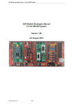
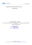
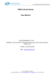
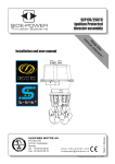
CAR-A-WAN.automotive Plus CAR-A-WAN.coach Plus Optimized vehicle 2G/3G router with integrated WLAN-Hotspot Manual CAWv4E5321gw / CAWv4E5321gwP CAWv4E5321gwC / CAWv4E5321gwPC CAWv4-SE-f3307 / CAWv4-SE-f3307 Plus (g CAWv4-SE-f5521gw / CAWv4-SE-f5521gw Plus ( August 2013 CAR-A-WAN.automotive Manual Index Page 2 of 52 1 Description 6 2 Warranty Terms 7 3 Limitation of product liability 8 4 Safety 9 4.1 General safety advice 9 4.2 Incorrect installation 9 4.3 12V/24V-connection 9 4.4 Mobil communication aerial 9 4.5 Device fitting 10 4.6 Risk of Injury 10 4.7 Danger of material damage & injury risk during assembly 10 4.8 Damaging the airbags 10 4.9 Damaging important vehicle parts 10 4.10 Maintenance, Service und Faults 11 5 Introduction 12 6 System description 13 7 Device description CAR-A-WAN.automotive / .coach 14 7.1 Front Panel Components 14 7.2 Display and ports on the rear 15 7.3 Identification label 16 7.4 Mounting bracket 16 7.5 Acoustic signals of the CAR-A-WAN.automotive / .coach 17 8 Storage and Unpacking 18 8.1 Storage of the CAR-A-WAN.automotive / .coach 18 8.2 Unpacking of the CAR-A-WAN.automotive / .coach 18 CAR-A-WAN.automotive 9 Manual Installation und connection of the CAR-A-WAN.automotive / .coach 19 9.1 Voltage supply of the CAR-A-WAN.automotive / .coach 19 9.2 Antenna connectors of CAR-A-WAN.automotive / .coach 20 9.3 Installation order 20 9.3.1 Mounting bracket 20 9.3.2 Power 20 9.3.3 Thoughts on SIM-Cards 21 9.3.4 De-activating the SIM-Pin 21 9.3.5 Routing of antenna wire – avoid damage! 21 9.3.6 Installation of Oracle’s JAVA (formerly SUN JAVA) 22 9.3.7 Installation of CAR-A-WAN.automotive / .coach Monitor 22 10 Device Operation and Function 23 10.1 CAR-A-WAN.automotive / .coach Monitor Usage 23 10.1.1 Find Router 24 10.1.2 Router Logs 24 10.1.3 Reset Modules 24 10.1.4 Disconnect CAR-A-WAN.automotive / .coach Control from CARA-WAN.automotive / .coach 24 Modules 24 10.1.5 10.1.5.1 Power 24 10.1.5.2 Ready 24 10.1.5.3 Dialing 25 10.1.5.4 Online 25 10.1.5.5 Hang up 25 10.1.6 25 Signal strength und Registration status 10.1.6.1 Yellow: 2G 25 10.1.6.2 Green: 3G 25 10.1.6.3 Blue: Bluetooth 25 10.1.7 26 Dial All Page 3 of 52 CAR-A-WAN.automotive Page 4 of 52 Manual 10.1.8 Hangup All 26 10.1.9 Load Router Configuration. 26 10.1.10 Save Router Configuration. 26 10.1.11 Hide Tabs. 26 10.1.12 Show Statistics. 26 10.1.13 Disconnect CAR-A-WAN.automotive / .coach 26 10.1.14 Router Discovery Dialog 26 10.1.15 CAR-A-WAN.automotive / .coach-Monitor Transfer Chart 27 10.1.16 Configuration Dialog (General) 28 10.1.17 Configuration Dialog (Display) 29 10.1.18 Configuration Dialog (Misc) 29 10.2 CAR-A-WAN.automotive / .coach Web-Administration usage 30 10.2.1 CAR-A-WAN.automotive / .coach Web-Administration start up 30 10.2.2 The landing page 31 10.2.3 User Management / Change Password 32 10.2.4 Module Settings / Global Settings 33 10.2.5 Module configuration 34 10.2.6 Host-Access point 35 10.2.7 Permitted WLAN channels 36 10.2.8 Routing 37 10.2.9 DHCP 38 10.2.10 DNS 38 10.2.11 Port redirections 39 10.2.12 Bluetooth PAN Devices 40 10.2.13 Power management 41 10.2.14 Channel bundling 42 10.3 Operating modes and notifications 42 11 Commissioning the CAR-A-WAN.automotive / .coach 43 12 Troubleshooting 43 CAR-A-WAN.automotive Manual 12.1 Service-Protocol 47 12.2 Service-Hotline 47 13 Technical Data 48 13.1 Specification CAR-A-WAN.automotive / .coach 48 13.2 Specification 12V/24V-Power supply cable (front side) 48 13.3 Specification CAN connector (rear side) 48 13.4 Accessories 49 14 Recycling of the CAR-A-WAN.automotive / .coach 50 15 Identification of CAR-A-WAN.automotive / .coach 50 Declaration of conformity 51 Page 5 of 52 CAR-A-WAN.automotive Manual 1 Description The abbreviation CAW is used in this manual for CAR-A-WAN.automotive / .coach. The version descriptor v4 is not used in the manual. The following symbols will be used in this manual: Warning symbol; please obey to protect your health, operation and safety. Information symbol; highlights additional Information und Tips. Recycling symbol All components and parts marked with this symbol are subject to toxic waste disposal. Never throw these components into the general rubbish This equipment is intended for the legal use in vehicles in all countries if EU (and all countries, who accept EC directive 1999/5/EC), an exception is France: Outdoor usage of WLAN has to be limited to 10mW e.i.r.p. within the frequency range between 2545 and 2483.5 MHz. Copyright© 2012 All Rights Reserved. This manual is copyright protected. The copyright owned by the company IPmotion GmbH. Registered Trade Mark: All Trade Marks used are registered property of their respective owners. IPmotion® and CAR-A-WAN® are Registered Trade Marks. Technical and optical alterations as well as print errors accepted Page 6 of 52 CAR-A-WAN.automotive Manual 2 Warranty Terms The invoice is considered as proof of first purchase and should be retained. It is needed for warranty claims. If the product is sold to another user, then the remaining warranty period will still be valid. The proof of purchase as well as this explanation should be passed on together with the product. We warrant this equipment to be in a fully functional condition and that the technical descriptions contained within the attached documentation are valid. The warranty period for electronic vehicle components is governed by local legislation. This warranty does not cover the following cases: o Defects through: freight damage, accident, natural disasters, abuse, vandalism, inappropriate use, incorrect maintenance or wrong third party repair. o Unauthorized changes/interferences, faulty operation, other equipment or accessories, wrong installation, or other modifications not authorized by us. o Ignoring the instructions provided in the documentation. o Product incompatibility after purchase due to possible technical innovations or regulations. o Incompatibility or malfunctioning caused through product components not installed by us. o Normal wear and tear. o Defects which are caused by external devices. The warranty period for replaced and/or repaired parts expires with the original warranty period for the product. Faulty devices, which are returned without accessories, are replaced without accessories. A returned device is only accepted provided if it was placed in the original packaging to avoid transport damages. Incidental transport costs are generally excluded from the warranty. IPmotion GmbH gives neither explicit nor implicit warranties regarding this equipment and its quality, marketability, or suitability for a certain purpose. In some countries the exclusion of an implicit warranty is legally not valid. In this case the validity of all requirements and implicit warranties is limited to the warranty period. At the end of this period all warranties lose their validity. In some countries a limitation of the validity period of implicit warranties is legally not binding, so that above restriction do not come into play. Page 7 of 52 CAR-A-WAN.automotive Manual 3 Limitation of product liability Claims for damages are ruled out, unless they are based on pre-meditated actions or negligence of the IPmotion GmbH or their employees. The adhesion after the product liability law remains untouched. We are under no circumstances responsible for: o Third party demands due to losses or damages. o Loss or damage of your recordings, files or data, or the costs of the replacement of data. o Economic damages (including lost profits or savings) or associated damage, even if the employees of the IPmotion GmbH were informed about the possibility of such damage. Under no circumstances is IPmotion GmbH responsible for any coincidental, indirect, special, subsequent or other damages of any kind (inclusively of unlimited damage concerning loss of profit, business interruption, loss of business information or any other losses), due to the use of the CAR A WAN.automotive / .coach or in any other association with the equipment, be it on contract, payment of damages, carelessness, liability, or other demands are raised, even if IPmotion GmbH were informed in advance about the possibility of such damage. This exclusion also encompasses any liabilities, arising from demands of third parties placed on the original buyer. In some countries, the exclusion, or the imitation of supplementary- or subsequent damages is legally not binding, so that the above statement does not come into play. Page 8 of 52 CAR-A-WAN.automotive Manual 4 Safety 4.1 General safety advice Before you proceed, please read the user manual and the safety references in this chapter carefully, (transport, storage, connection, start-up, etc.). Authorised personnel only are to carry out work on the router and antennas 4.2 Incorrect installation Inappropriate installation can lead to damage to the equipment or vehicle! The installation of the equipment requires special knowledge and skills. It is strongly recommended to have the installation carried out by an authorized workshop. 4.3 12V/24V-connection Use the accessories cable provided for the connection to the 12V/24V DC onboard power supply of your vehicle. When connecting the CAR-A-WAN.automotive / .coach without adaptor cables, the power supply of the CAR-A-WAN.automotive / .coach must be fitted with a single use 1A (T) fuse. 4.4 Mobil communication aerial The installation of transmitter antenna cables in vehicles is not recommended without expertise and suitable tools. Badly manufactured or arbitrarily shortened or extended high frequency antenna cables can cause bad reception and could interfere with other devices. Not observing minimum kink radii of antenna cables can lead to damaged cores. This can result in bad reception and poor transmitting powers. Page 9 of 52 CAR-A-WAN.automotive Manual 4.5 Device fitting The router is intended to be installed in vehicles. Specific mounting brackets are available, to click the CAR- A-WAN.automotive / .coach into. Location and position determine the number of mounting brackets required. One mounting bracket is required if mounting outside the cabin, e.g. in the trunk or glove compartment. Two mounting brackets are required if the device is located within the cabin. Do not install or operate the equipment in damp areas and keep liquids away from the equipment. The router should be installed away from other heat sources, to allow the aluminium housing to dissipate any generated heat. Do not block the cooling vents of the CAR- A- WAN.automotive / .coach and ensure good air circulation. 4.6 Risk of Injury Unsuitable locations, missing or insufficiently fixed mounting brackets can cause injuries and traffic accidents. 4.7 Danger of material damage & injury risk during assembly When levering out claddings, pointy or sharp tools can lead to injuries and damage the unit. Lever parts carefully. Do not exert direct pressure on leads. 4.8 Damaging the airbags If the unit is installed too close to the airbag, the airbag could be damaged or its function be impaired. Mount the components out of the effective range of the airbags 4.9 Damaging important vehicle parts Important vehicle parts and wiring can be damaged while drilling holes or driving of self-tapping screws. Ensure sufficient space behind the screw and boreholes. Page 10 of 52 CAR-A-WAN.automotive Manual 4.10 Maintenance, Service und Faults Repairs should be carried out by qualified personnel only. Only use spare parts that do not change the safety regulations of the CAR-A-WAN.automotive / .coach. Software updates should only be carried out under instruction and during the update the device must be under a permanent power supply. An interruption of the power supply can lead to a complete failure of the CAR-A-WAN.automotive / .coach. Software updates should only be carried out when there is sufficient mobile coverage, because the size of the updates may increase transmission time beyond the length of the follow-up time of CAR-A-WAN.automotive / .coach. Page 11 of 52 CAR-A-WAN.automotive Manual 5 Introduction This manual contains fundamental information about the vehicle-connected router with integrated Wireless LAN Hotspot, i.e. how it operates, the application of the different functions and troubleshooting. Further, this manual contains references on how to configure, use and install the unit. Contents of this technical manual was accurate at the time of printing, it however can change due to progressive technology. We welcome any feedback on errors. No liability will be accepted for any errors in this manual nor their consequences. The CAR-A-WAN.automotive / .coach is designed to connect computers, laptops, notebooks and Smart phones, electronic cash registers with Internet-Cash-function and other TCP / IP-enabled devices such as webcams from the vehicle to the Internet: o Via wired LAN o Via wireless WLAN The CAR-A-WAN.automotive / .coach autonomously performs dial up to connect to the Internet and redials in case of connection failure. Furthermore, dialing rules are taken into account, such as a roaming lock or minimum signal quality. With the Plus version, the second WAN link o parallel or o alternative can be used to secure the connection in terms of their availability: Two contemporaneous connections are used as a parallel connection and new connection requests are distributed to the two connections, whereby a chosen pathway is maintained until the conclusion of each, previously used WAN connection. If the two WAN connections are initially established as 2G connections (GPRS / EDGE) and one connection switches to a 3G connection, all data traffic is diverted to the faster 3G connection on, while the slower 2G connection is disabled. Page 12 of 52 CAR-A-WAN.automotive Manual 6 System description The Linux Router CAR-A-WAN.automotive / .coach connects local devices to the Internet via LAN or WLAN, using up to two data modems. Integrated rules and user-defined rules control the dial-up behavior,. The shut down delay time and the nearly complete shutdown of the 12V DC power supply is controlled by power management. It also controls the correct manual cold start as well as the watchdog triggered restart by the embedded PCs. A SIM card is directly connected to the 2G / 3G modem, LEDs indicate operating status, a speaker is fitted for alarm chimes, and a switch is wired for the re-set of the router. The modems dissipate their heat generated during operation to the aluminum housing. Plug in power supply and antenna cables make installation easy and no tools are required. Turn-off delay Fig.1: Block diagram Page 13 of 52 CAR-A-WAN.automotive Manual 7 Device description CAR-A-WAN.automotive / .coach This chapter deals with the relevant device components, operating instructions and directions concerning all connections. 7.1 Front Panel Components Fig.2: Front view The front panel has (left to right) ports for LAN (RJ45 100 MBit/s), plugs for the mobile antenna (left module 1, right module 2), the SIM slots (top for module 1, bottom for module 2), USB 2.0 and the power supply socket. a) LAN-Connection (RJ45): The LAN interface and wireless interface are bridged to enable the connection to LAN instead of WLAN. Devices that are connected via LAN can connect to devices connected via WLAN. Two LEDs provide information about the state of the connection: The green LED on the left illuminates to indicate an existing cable connection and flashes when receiving data, while the orange LED on the right lights up when the router is on and flashes when transmitting data. b) FAKRA Main connector for mobile phone antennas The burgundy colored connectors are vibration-proof and make for reliable contact, but must be handled carefully when plugging in the socket. Rough handling can bend the center spine, which results in severe interference. Therefore please check; the position of the contacts before connecting the FAKRA jack on the antenna side . (Use a magnifying glass if necessary.) c) SIM-Cards SIM/U-SIM-Cards CAR-A-WAN.automotive / .coach single, SIM 1 in the top slot CAR-A-WAN.automotive / .coach Plus double, SIM 1 in the upper slot CAR-A-WAN.automotive / .coach Plus double, SIM 2 in the lower slot We recommend disabling roaming locks and the SIM-pin. Page 14 of 52 CAR-A-WAN.automotive Manual Please slide the SIM card for module 1 into its slot, cut out side first, gold contact surfaces face down. This is the same for the SIM card for module 2, cut out side in first, , however gold contact surfaces have to be facing up. b) Backup 12V/24V-Input: The CAR-A-WAN.automotive / .coach has no built in fuses. Therefore, both possible power supply cables require a 1A fuse. The optional car power cable with a 12V accessory plug has an internal 1A fuse. The cables used for hard wiring the device into the vehicle should be overload protected in the fuse box. Should this not be possible, insert an in line fuse holder. 7.2 Display and ports on the rear Fig. 3: Rear view On the rear is (left to right) the connection for CAN, GPS (FAKRA / SMB-A blue and wireless LAN (FAKRA / SMB-A beige), three status LEDs (circle, triangle and square). The following operating conditions are read from the LEDs: o Only is illuminated: ready, but not dialed in o (1) or (2) flashing, illuminated: Module is dialed in, slow flashing 2G, fast flashing 3G o (1) or (2) flashing, flashing: As above, but roaming, at least one module o Only flashing: Ready, but not dialed in, as no roaming is requested o (1) or (2) illuminated, illuminated: Ready, but illuminated module not ready to dial o Continuous illumination of ,and : Software Update in progress, do not switch off the power unit under any circumstance o No LED lights illuminated, not even at the RJ45 port on the front: Device not turned on Page 15 of 52 CAR-A-WAN.automotive Manual 7.3 Identification label Contains information Manufacturer on: Device Model IMEI-Number(s) Serial Number CE- und Barcode- Labeling 7.4 Mounting bracket Fig. 4: cross section Fig. 5: View with drilled holes A plastic mounting bracket (PVC) is available for the CAR-A-WAN.automotive / .coach . It provides a secure attachment. Within the cabin, a second mounting bracket can be installed – maximum safety is achieved when it is fixed on all sides and the two brackets are at a maximum distance. Page 16 of 52 CAR-A-WAN.automotive Manual 7.5 Acoustic signals of the CAR-A-WAN.automotive / .coach Currently none Currently none Page 17 of 52 CAR-A-WAN.automotive Manual 8 Storage and Unpacking 8.1 Storage of the CAR-A-WAN.automotive / .coach If the device is not installed immediately, one should ensure: o The equipment and accessories are kept in the original packaging when warehoused. o Recommended temperatures for storage in the original packaging are: -30 ° C +70 °C. o The device and packaging are protected from moisture. 8.2 Unpacking of the CAR-A-WAN.automotive / .coach Remove shipping boxes and packing materials Check the delivery against the delivery docket. If the delivery is incomplete, or if you receive a wrong delivery, inform the supplier immediately. Also check the shipment for transport damage. Damage during transportation should be claimed immediately: Page 18 of 52 o Keep shipping boxes and packing material for inspection. o Immediately notify the manufacturer or the supplier. o Immediately notify the freight forwarder/ shipping company. CAR-A-WAN.automotive Manual 9 Installation und connection of the CAR-A-WAN.automotive / .coach The listed technical requirements for the environmental and operating conditions must all be followed to ensure the correct functioning of the CAR-A-WAN.automotive / .coach. For the successful installation of the CAR-A-WAN.automotive / .coach the following must be observed: o Only people with competence in automotive electrics should install the device themselves. o To simplify installation, you will receive a cable with a fuse to fit the accessory socket, (refer chapter ‘Accessories’. o Ensure adequate ventilation for the CAR-A-WAN.automotive / .coach. o Take care when routing the antenna cables. Knots and tight bending can lead to fractures in the antenna cables and conductors. o The cables should be at room temperature before installation. o The device is equipped with color-coded system plug-in connections to avoid reverse polarity. An exception is the stub antenna which is threaded, 9.1 Voltage supply of the CAR-A-WAN.automotive / .coach Please observe the connection depicted in the diagram (Fig. 7) below: Fig. 6: Connection on-board electrics Fuse: 2 x1 A slow, behind each terminal 30 and terminal 15 Cable section min. 0.50 mm² / max. 0.75 mm² Power consumption at 12V Typically 550 mA, not more than 750 mA Power consumption at 24V Typically 630 mA, not more than 750 mA Pin assignment Pin 1 (red): Steady plus (KL30) 12V24V DC DC 12V/ DC 30 1A 1A 15 31 Pin 2 (yellow): Switching plus (KL15) Pin 3 (black): Ground (KL31) Page 19 of 52 + o - CAR-A-WAN.automotive Manual 9.2 Antenna connectors of CAR-A-WAN.automotive / .coach The CAR-A-WAN.automotive / .coach lacks built-in antennas; it however has external antenna jacks to improve reception in the car (Faraday cage) and to reduce the radiation emitted in the interior. The unit is supplied with disc mount antennas with sockets. Each antenna cable is 3 meters long, to provide sufficient reception in cities and on highways. It is manufactured in RG174. Due of regulations take care of a minimal distance of 20cm; to prevent a crosstalk between the two radios it’s recommended to have a distance of 180 cm to 220 cm. It is advisable to trace the route of the cable by means of a piece of string, before bonding the antenna to the relevant cable. Should the cable end up less than 2 meters long, a qualified technician is required to cut, and attach a new burgundy FAKRA-D socket to the cable. Figure 8 (top): 3G antenna with an adhesive bonding surface (use an alcohol wipe for cleaning the sticking area). The amplification is 0dBi, ie in areas with weak coverage the RG174 cables should be cut to the minimum length. Ideal for side window between C -& D-columns. Figure 8 (middle): 3G Ronda antenna, its design lends itself for application vehicles with high roofs, such as tour buses, vans, emergency vehicles and general public transport vehicles, comes without or with GPS. Available cable length: RG 58 3m, RG58 5m, RG 58 8m (with GPS only RG 174 3 m) Figure 8 (bottom): WLAN Ronda antenna for mounting of thin surface like covers. 9.3 Installation order 9.3.1 Mounting bracket Install mounting bracket to ensure the CAR-A-WAN.automotive / .coach is securely attached and can reach a power supply. 9.3.2 Power Install the power cord, starting with the earth, then ignition, then permanent positive. Or plug the supplied power supply cable into the accessory plug. Check the device, for no more than 30 seconds, by connecting power to the device. The right, orange LED on the network should begin to glow. Disconnect the device the from power supply by pressing on the top of the plug and pulling it out. Turning off the ignition is not enough as the device has electronic tracking. Page 20 of 52 CAR-A-WAN.automotive Manual 9.3.3 Thoughts on SIM-Cards Have the SIM cards ready. It is recommended to allocate the SIM cards to one of the two modules. Module 1 is addressed about 30 seconds before module 2 in the Plus version of the device as it prepares for dial up.. When both modules are online, they are both used for data transfer, provided connections are not terminated (e.g. due to poor signal quality) and initiated data paths will remain in operation. If you have a choice between a faster, less reliable connection and a slower, more reliable connection, insert the relevant SIM, card matching your preferred choice of network, into the SIM card module 1. We recommend to use the more reliable connection and associated SIM card in module 1. CAR-A-WAN.automotive / .coach is supplied without a SIM pin and it is recommended to disable the SIM pin function if you are the only person to have access to the router and the SIM cards. 9.3.4 De-activating the SIM-Pin Please disable the SIM Pin of your SIM card in your phone now. If this is not successful (this can sometimes be the case), keep in mind that we have to tell CAR-A-WAN.automotive / .coach the PIN for permanent storage and need to avoid mixing up the SIM cards to avoid having them inadvertently locked. Do not insert the SIM-card yet! 9.3.5 Routing of antenna wire – avoid damage! Some important tips for finding the right place (s) for the antenna (s): First try to trace the optimal path for the antenna cable with string. If this is successful, you can now test the antenna. Refer to the chapter about real-time monitoring with the JAVA-based CAR-A-WAN monitor. Measure the required length and, if necessary, have the cable cut to length by a qualified technician. Clean the potential mounting sites with the alcohol wipe and place the antenna (s) carefully in the final position and do not glue the antenna just yet. Page 21 of 52 CAR-A-WAN.automotive Manual 9.3.6 Installation of Oracle’s JAVA (formerly SUN JAVA) You need JAVA ™ to operate the CAR-A-WAN.automotive / .coach monitor. Please search for http://www.java.com to download the appropriate version for your operating system and install it. 9.3.7 Installation of CAR-A-WAN.automotive / .coach Monitor You will find the up to date version for your local installation on the Router (JAVA version) under: http://10.10.10.1:8888 (Standard setting) Unpack the ZIP archive and look in the sub file: cawmonitor.jar Page 22 of 52 CAR-A-WAN.automotive Manual 10 Device Operation and Function The operation of this router has different modes and messages that may be displayed on the CAR-A-WAN.automotive / .coach monitor by means of the JAVA program. You have already downloaded the program from the internal website of the CAR-A-WAN.automotive / .coach. 10.1 CAR-A-WAN.automotive / .coach Monitor Usage Fig. 9: CAR-A-WAN.automotive / .coach monitor with two modules dialed in The CAR-A-WAN.automotive / .coachMonitor appears after dial up via a double click (Windows and Linux) or a single click (Apple) with cawmonitor.jar. The mouse can be used to position it anywhere on the screen. The screen position is saved, even after closing the application, after CAR-A-WAN.automotive / .coach Monitor is opened from a local installation and in the Config. Settings dialog (display), the tick box Save window positions and sizes after modifications is selected. Fig. 10: The tabs show details of the connections. Select show tabs to display detailed information about the status of the connected modules: The CAR-A-WAN.automotive / .coach Monitor offers a docked connection details and in addition to the total content summary including the display of the tunnel condition, individual information such as the IP address of each module. Unfolded connection details appear below the monitor in a summary view area, detailing IP address, connection status and data throughput for each module and for the Tunnelpipe (the channel bundling.) . Hide tabs closes the connection details again. Page 23 of 52 CAR-A-WAN.automotive Manual 10.1.1 Find Router CAR-A-WAN.automotive / .coach, connected to same subnet as the PC, are automatically detected. CAR-A-WAN.automotive / .coach is configured to other subnets can be installed here. The subsequent dialog relevant to this can be found in Router Discovery Dialog. 10.1.2 Router Logs During operation, diagnosis while synchronized with the CAR-A-WAN.automotive / .coach support, displays and analyses detailed settings. A local syslog client is required for this, necessary adjustments are made in the subsequent dialog. 10.1.3 Reset Modules Use this icon when modules are not responding or you want to force a Reconnect after a network-based service change or reactivation (e.g. after a SIM card block),. 10.1.4 Disconnect CAR-A-WAN.automotive / .coach Control from CAR-A-WAN.automotive / .coach This program button closes the connection between A-CAR-CAR-A-WAN.automotive / .coach and WAN.automotive / .coach Control; for example, use it when establishing a new connection to another device. 10.1.5 Modules Individual modules can be contacted directly and made to dial up or disconnect. Possible statuses of the modules are: 10.1.5.1 Power The module is responsive, but not initialized completed: Common error: The SIM PIN is stored in the configuration dialog incorrectly, or the SIM card is blocked due to repeated false entry of the PIN 10.1.5.2 Ready The module is initialized and the SIM PIN has been confirmed. Page 24 of 52 CAR-A-WAN.automotive Manual 10.1.5.3 Dialing The dialing process is started. 10.1.5.4 Online The module is dialed in and connected to the network. 10.1.5.5 Hang up The hang up process is initiated. 10.1.6 Signal strength und Registration status After the initialization of the modules (all module states except power), the signal strength and the currently available wireless technology are displayed. The signal strength, network operator and the registration status will be displayed as a tooltip. Hovering the mouse pointer over the bar display will open up a help window. The registration status has four modes: Home, Roaming, Limited Service and Registering. The CAR-A-WAN can only go online when Home or Roaming appears. Also refer to Chapter 12, Troubleshooting. Furthermore, a colored vertical bar is shown, the = height referring to signal strength and the color to the type of connection: 10.1.6.1 Yellow: 2G GPRS / Edge can be received almost everywhere in Europe. A yellow bar should be visible after two minutes when properly logged into a wireless network (SIM PIN disabled or correct SIM PIN stored, APN may be wrong, see Troubleshooting, Chapter 12) if the cables are intact and the antennas are wired properly.. 10.1.6.2 Green: 3G UMTS or 3G can be accessed frequently in cities and on highways. The signal strength is generally weaker with 3G, achieving download speeds, when stationary, of up to 7-20 Mbp and, while driving 128Kbit / s to 1568 Kbit / s. 10.1.6.3 Blue: Bluetooth After successful pairing, up to 8 other modules can be connected via personal Aerial network profile as gateways. The blue bar is not an indicator of transmission power, but is an idealised representation. Page 25 of 52 CAR-A-WAN.automotive Manual 10.1.7 Dial All Initiates dial-up for all available modules. 10.1.8 Hangup All Initiates disconnect for all available modules. 10.1.9 Load Router Configuration. Loads locally stored settings for the CAR-A-WAN.automotive / .coach monitor as well as default values. Warning: The setting of the CAR-A-WAN.automotive / .coach (Provider, SIM PIN etc.) will be done in the Web interface as described in chapter 10.2.5. 10.1.10 Save Router Configuration. Settings are stored from the CAR-A-WAN.automotive / .coach monitor in an archive in TAR format, a data format without data compression. 10.1.11 Hide Tabs. Hide/ displays enlarged images of module states, including the tunnel pipes. See also CAR-A-WAN.automotive / .coach monitor opened connection details. 10.1.12 Show Statistics. Displays detailed connection statistics per module. See also CAR-A-WAN.automotive / .coach Monitor Transfer Chart. 10.1.13 Disconnect CAR-A-WAN.automotive / .coach This program button closes the connection between CAR-A-WAN.automotive / .coach and CAR-A-WAN.automotive / .coach Control, for example when establishing a new connection to another device, or to close a disrupted connection after a reset or restart - click on program button again to re-connect. 10.1.14 Router Discovery Dialog Fig.7: Displays active CAR-AWAN.automotive / .coach This window is used for manual configuration and displays information about the IP address of the CAR-A-WAN.automotive / .coach, the number of modules, firmware version, MAC address and current availability. Should your CAR-A-WAN.automotive / .coach not be in the same subnet as the PC used to monitor and control it, you can manually add an IP address and connect here under the Add tab. Page 26 of 52 CAR-A-WAN.automotive Manual 10.1.15 CAR-A-WAN.automotive / .coach-Monitor Transfer Chart Fig. 12: Graph with history of the data connection and signal strength for the current module. A multicolor graphic per module displays current information on sent and received data as well as lost data. The scale automatically adjusts to the recent average and displays it on the left side. In addition, the signal strength is displayed if the module can support it during its operation. Page 27 of 52 CAR-A-WAN.automotive Manual Fig.13Detailed Information about the actual module Double-click the chart to access a property page, the chart’s data values can also be saved as a snapshot. 10.1.16 Configuration Dialog (General) Fig.8: General Settings for CAR-A-WAN.automotive / .coach Monitoring-Client and CAR-AWAN.automotive / .coach GPS signal quality logging: Used to record values from test drives and compares the relationship between distance traveled and data throughput or signal strength, e.g. for display in Google Earth. For use with USB GPS “cursor” tested with the GPS receiver from Holux GR-213 and Modem 1 For information on the conversion of CSV data into KML for visualization follow this link:http://code.google.com/apis/kml/documentation/kml_tags_21.html Figure 15: Data throughput rates created with the use of CAR-A-WAN.automotive / .coach and Google Earth. Page 28 of 52 CAR-A-WAN.automotive Manual 10.1.17 Configuration Dialog (Display) Fig.9:Display settings for CAR-A-WAN.automotive / .coach Monitoring-Client Show tray icon: Displays the Icon, when the CAR-AWAN.automotive / .coach Monitor is minimized. Show router tabs: Constantly displays the module details Auto save window setup: Saves the window position Auto load windows setup: Sets the previous window position when starting up again. 10.1.18 Configuration Dialog (Misc) Fig.10: Various settings for the CAR-A-WAN.automotive / .coach Monitoring-Client and CAR-AWAN.automotive / .coach Current Proxy state: Online or offline, offline by default in the CAR-A-WAN.automotive / .coach, because the RAM disk is not suitable for permanent auto-storage and is disabled here. Remote Administration: Opens the CAR-A-WAN.automotive / .coach temporarily for SSH, but requires the user to enter information for the public IP address of the CAR-A-WAN.automotive / .coach. This displays the access status of SSH between the WAN and router. Shutdown Router: Shutting down the CAR-A-WAN.automotive / .coach. A restart can only take place when the power supply is shut off and reconnected again. Restart Router: Performs a new start (cold start) on the CAR-A-WAN.automotive / .coach . Switch offline: (temporary user cache; function disabled) Page 29 of 52 CAR-A-WAN.automotive Manual Keep Proxy offline: (Permanent disconnection from the network until the next reboot of the CARA-WAN, independent of the dial up status of the router; function disabled) 10.2 CAR-A-WAN.automotive / .coach Web-Administration usage For changes to the basic settings of the CAR-A-WAN.automotive / .coach the Administrator Web site is available and can be addressed directly and, unlike the CAR-A-WAN.automotive / .coach monitor, is executable without having to install JAVA. All you need is a Web browser (no JavaScript required) and a network connection to the CAR-A-WAN.automotive / .coach. A computer user can change the configuration values, but should have basic knowledge about the configuration of routers and wireless LAN access points available. Before you configure the CAR-A-WAN.automotive / .coach or administer it, you should have the following information on hand: SIM-PIN (See 9.3.4) APN, dial command User / Password for PPP-authentication 10.2.1 CAR-A-WAN.automotive / .coach Web-Administration start up http://[IP-Adressof the CAR-A-WAN.automotive / .coach]:8888/ Standard Setting: http://10.10.10.1:8888 User: [Not displayed]/ Default-Password: [Not displayed] Locate the print out of the equipment data form, the second page in the ‘Notizen’ section, contains passwords for your device, WLAN and web. Page 30 of 52 CAR-A-WAN.automotive Manual 10.2.2 The landing page Fig.11: Splash screen with link to administration page The main page refers to several links, including the administrator’s menu. The third is to a webpage stored within the IPmotion web server and with tools, including remote maintenance. After clicking on “Click here to proceed to administration” you will be redirected to the configuration of the first module. Fig.12: Module configuration Page 31 of 52 CAR-A-WAN.automotive Manual 10.2.3 User Management / Change Password Fig.13: Dialog to set the Web administrator’s. Password In this dialog you can change the password of the administrator. An empty password is not allowed. Please note that the documentation of the CAR-A-WAN.automotive / .coach is downloadable through the website without verifying the person. If you do not modify the administrator password, any person can configure the router from the LAN. We strongly recommend setting a password to prevent abuse. Please write this password down and store it in a safe place. The CAR-A-WAN.automotive / .coach does not have an integrated process for resetting the password of your choice. Should a password reset be required, it has to be carried on the operating system of the CAR-A-WAN.automotive / .coach and charges will be incurred for these services. Page 32 of 52 CAR-A-WAN.automotive Manual 10.2.4 Module Settings / Global Settings Fig.14: Global Settings The following module settings are principally independent of each other, i.e. the modules can be configured independently. However, both can have dial-up rules set. In this example, an existing, slow 2G (GPRS / Edge) will be discontinued when the other module was able to establish a faster 3G connection (UMTS / HSDPA / HSUPA). Establishment or maintenance of connections is still subject to minimum signal quality.. A value of -1 (in words: minus one) deactivates minimum signal strength for the dial-up. Page 33 of 52 CAR-A-WAN.automotive 10.2.5 Module configuration Fig.15: Module configuration 1 Page 34 of 52 Manual CAR-A-WAN.automotive Manual The menu for the configuration of the data modules allows for changes that affect the authentication in regards to the dial up and the type of command transfer between the CAR-A-WAN.automotive / .coach and integrated data modules. All other fields not described here should only be changed in response to IPmotion support directives and these changes could cause a malfunction or even a fatal defect in the CAR-A-WAN.automotive / .coach. PIN (PIN of the SIM card) is displayed hidden, please ensure that the password manager of your web browser does not recognize this value as a password. This is a common cause of error to be recognized if the module status displays “Power“ instead of „ Ready“ or“ online“) Provider APN: Recognizes the network provider Username & Password (this information is provided by your cell phone provider) Allow auto dialing (This setting controls whether the module can dial when it is ‘Ready’ and has found a cell phone provider. Always (re-dial will be always carried out after the connection was interrupted.) Never (manual dialing can only be performed through the CAR-A-WAN.automotive / .coach Monitor) When not roaming (choose this option to prevent dialing into a foreign network (international). This only prevents a new dial-up, it does not disconnect an existing connection to a foreign network.) PIN-String (If the SIM card PIN is disabled, then the content of this field has to be deleted. If a SIM PIN is used, type (without inverted commas): ‘AT + CPIN =’(not case sensitive)), if not filled automatically. 10.2.6 Host-Access point Fig.16: Configuration of the Access points The optional wireless LAN access point can be switched on or off; the network ID change d and a channel chosen. Please ensure you utilize free and unrestricted WLAN channels applicable in your country, refer to next page. Page 35 of 52 CAR-A-WAN.automotive Manual 10.2.7 Permitted WLAN channels Channel Number Frequency (GHz) Permitted in 1 2,412 Europe, USA, Japan 2 2,417 Europe, USA, Japan 3 2,422 Europe, USA, Japan 4 2,427 Europe, USA, Japan 5 2,432 Europe, USA, Japan 6 2,437 Europe, USA, Japan 7 2,442 Europe, USA, Japan 8 2,447 Europe, USA, Japan 9 2,452 Europe, USA, Japan 10 2,457 Europe, USA, Japan 11 2,462 Europe, USA, Japan 12 2,467 Europe, Japan 13 2,472 Europe, Japan 14 2,484 Japan Source: http://en.wikipedia.org/wiki/Wireless_LAN Page 36 of 52 CAR-A-WAN.automotive Manual 10.2.8 Routing Fig.17: Routing The CAR-A-WAN.automotive / .coach routing menu has a configurable network interface. In the standard configuration a second routing interface is not provided, however, in principle it is conceivable. For example, if the Host Access Point is disabled for WLAN and the WLAN card is enabled, functioning as a transition to other networks. Page 37 of 52 CAR-A-WAN.automotive Manual 10.2.9 DHCP 10.2.10 DNS The CAR-A-WAN has its own DNS server and is bound to the address of the router and is always switched on. This DNS server has the peculiarity that it does not directly contact the local cell phone DNS server but it directs its inquiries to the root servers where the data is received and communicated further via the typical DNS server back to the hosts. This type of communication is inherently slower than communication with the mobile providers, but the advantages is the use of multiple, parallel WAN Connections. Alternatively, an external DNS server can be set up in the DHCP configuration menu, which is passed on to clients like Google (8.8.8.8). In addition, here is a short list of freely accessible, and unlike Google, anonymous DNS servers: (see http://wiki.ak-zensur.de/index.php/Unzensierte_DNS_Server): 85.214.73.63 (anonymisierungsdienst.foebud.org) 194.150.168.168 (dns.as250.net, anycast DNS!) 213.73.91.35 (dnscache.berlin.ccc.de) Page 38 of 52 CAR-A-WAN.automotive Manual 10.2.11 Port redirections Fig.18: Port redirections In this menu, port redirection can be activated and de-activated by clicking on ’Active’; Applications can only be accessed from outside if the service provider allows inward routing and provides a public IP-Address. This is usually not the case and special services such as MDEX.de have to be utilized to securely publish device-internal services on the Internet or intranet. Page 39 of 52 CAR-A-WAN.automotive Manual 10.2.12 Bluetooth PAN Devices Fig.19: Bluetooth PAN In addition to the built-in data modules, the CAR-AWAN.automotive / .coach can be connected to up to eight other data modules via Bluetooth providing the following conditions are met: o The Bluetooth-Option has been purchased o Bluetooth-Dongle is plugged directly into an available USB 2.0 port before the start up (power on) o The Software Option was activated and o a Bluetooth PAN Profile platform data module is available (This can be a Microsoft Windows Mobile 6.0 Smartphone or later version, an iPhone (IOS 4.1) or an android phone. Page 40 of 52 CAR-A-WAN.automotive Manual 10.2.13 Power management Fig. 22: Dialog Channel bundling Page 41 of 52 CAR-A-WAN.automotive Manual 10.2.14 Channel bundling Fig.20: Dialog Channel bundling The channel bundling combines individual data streams to a common fail-safe connection. Enter the server address and your contract associated user Name and Password. After review, you can choose the modules to bundle and combine the data connections. Without channel bundling outbound connections can only be transferred (per process) through a single module. Without channel bundling, incoming data connections can still distribute the load via ECMP (Equal Cost Multi Path, a very fast load sharing option facilitated, directly through the Linux kernel), but relies on free access to public DNS servers. 10.3 Operating modes and notifications The description of main modes of the router as follows: o o o o o o Off On, Offline On, Online On, Roaming On, waiting for Shutdown Updating Page 42 of 52 CAR-A-WAN.automotive Manual 11 Commissioning the CAR-A-WAN.automotive / .coach To guarantee error-free operation, observe the following: 1. Check the SIM-Cards. 2. Check the fit of the antenna. 3. Check input fuses and turn on the ignition (or insert the 12V electrical plug into a socket board). 4. Wait Approx. 60 Seconds. 5. Switch your computer on and connect via WLAN or LAN. If all steps have been carried out successfully, the router should be “ON” mode. 6. Configure the device on the admin website. 7. Insert the SIM cards in their corresponding slots as follows: SIM 1 for module 1 in slot 1 (which is closer to burgundy colored antenna connectors than slot 2) - insert with golden contact area face down until it snaps into place and is flush with the fascia. SIM 2 insert with golden contact area facing up into slot 2 until it snaps into place and is flush with the fascia Restart the device via JAVA program-A-CAR WAN monitor (see Section 10.1.18) or just briefly disrupt the power supply. 8. Check the connection status with your PC. The router should be visible in WLAN after approx. one minute, and online after approx. 90 seconds. The router can now remain operational in this state. 12 Troubleshooting Authorized personnel only to carry out troubleshooting work on the hardware of the CAR-A-WAN.automotive / .coach. Page 43 of 52 CAR-A-WAN.automotive If the router is not functioning properly, please try to resolve the problem with the aid of the following table: Page 44 of 52 Manual CAR-A-WAN.automotive Manual Problem Possible cause Remedy The router cannot be started, no warning. The power supply for the router is not connected or turned off. Ensure that all connections are established and confirm this in corresponding voltage measurements. Check the mains input fuse of the CAR-A-WAN.automotive / .coach. I cannot see the WLAN of the CARA-WAN, even though my operating system has wireless connections available. The WLAN of the CAR-A-WAN is turned off, or other WLAN use the same channel or adjacent channels. Connect a LAN cable to the CAR-A-WAN and navigate to the Administration Web site and turn on the WLAN or change the channel (see Section 10.2.6). I cannot connect to the administration website. You have set a Disable the Web Proxy or bypass the proxy Web proxy in the server for local addresses. Internet connections of the Web browser. The module(s) cannot dial up, even though the SIM PIN has been entered. The tooltip in the CAR-AWAN monitor displays Home or Roaming (see Section 10.1.6). The pin-string was not entered. The PIN-String is a prerequisite for the transfer of the PIN to the modem. In the module configuration under ‘Advanced String’enter the pin string ‘AT+CPIN’ (without the ’inverted commas’) and save the change. Restart the router (see Section 10.1.18). The module(s) cannot dial up, but they display signal strength (see Section 10.1.6). The tooltip in the CAR-A-WAN Monitor shows Home or Roaming (see Section 10.1.6) The modules have possibly found available wireless networks, but cannot register in them. Ensure that, →the data-enabled SIM cards are inserted correctly (see Chapter 7) →the SIM card might need a SIM PIN , but is not correctly configured. →After inserting the SIM card or the reconfiguration of the SIM PIN, was reset (see Section 10.1.18). Page 45 of 52 CAR-A-WAN.automotive Manual The modules cannot successfully dial up, although they are registered on the network and the signal strength is * sufficient. The APN is incorrect, the user / password combination is incorrect; the SIM * Adequate signal strength for dial card is still not up is unique and dependent on unlocked by the network technology (2G/3G), provider or locked. modem, antenna and cables used The prepaid card and providers. You can set a global has run out of minimum value yourself, (see credit. Section 10.2.4) Ensure that, →the provider-specific data (APN / Username / password / authentication method) were transferred correctly to the CAR-A-WAN. →the SIM card is suitable for this application; please get in contact with the hotline of the network provider. The PC can dial into the VPN, but network resources are not accessible. The IP address of Change the IP address of the CAR-Athe CAR-AWAN.automotive / .coach under ‘Routing’. WAN.automotive / Restart the router (see Section 10.1.18). .coach is the same as the IP address of the VPN server. After around 30 minutes, the WLAN is no longer available and network connections are disrupted. The ignition has Turn on the ignition key to ‘accessories’ to been turned off or ensure power supply to the CAR-Athe accessories WAN.automotive / .coach. power supply has been switched off and the run-on time has been exceeded. The signal strength is weak, although a cell phone / USB stick with the same SIM card has a good signal strength display. The burgundy colored FAKRA socket in the housing is defect, the aerial cable is broken or the aerial cable has been bent too tightly.. Conduct a visual inspections of the plug, if necessary, replace the router or the aerial or the aerial cable. If you cannot find the identified error of the CAR-A- WAN.automotive / .coach in the table, contact our service department with the following information: 1. Model number, Serial number 2. Date of problem 3. Detailed description of the problem Page 46 of 52 CAR-A-WAN.automotive Manual 12.1 Service-Protocol Fill out all the setting changes that were made to the CAR-A-WAN.automotive / .coach, and enter the information into the service log. Date: Setting Changes, e.g. passwords etc.: Carried out by: 12.2 Service-Hotline Should the CAR-A-WAN.automotive / .coach experience any unexpected problems or if you need safety information, please contact our service hotline under: Tel.-Nr.: +49 641–350999-0 Fax Nr.: +49 641–350999-90 If the service hotline cannot be reached, use the following e-mail to contact us : [email protected] You can also contact us directly at the following Internet website address: http://www.ipmotion.de/en/support/contact/ Page 47 of 52 CAR-A-WAN.automotive Manual 13 Technical Data 13.1 Specification CAR-A-WAN.automotive / .coach WWAN bands GSM (900/1800 MHz) FDD I (2100 MHz) / FDD III (1800 MHz) / FDD VIII (900 MHz) Antenna gain using an adhesive window antenna < = 0dBi Antenna gain with screwed roof antenna and eight meters of low loss cable RG58 < = 0 dBi WLAN bands IEEE 802.11b/g 2.4 GHz antenna gain m. stumble antenna 0dBi Size: 112 x 30 x 184 mm (164 mm without protruding connectors, housing only) Power consumption: 7.6 Watt at 12V /7.6 Watt at 24V Closed circuit current: Mass (with two Modems): Classification: Functional temperature: Operational temperature:* Storage temperature: 0.9 μA 430 Gramm IP 20 -30 to 70 Degree Celsius -30 to 60 Degree Celsius -40 to 85 Degree Celsius * You suffer an injury if you touch the aluminum surface above 60 Degree Celsius. 13.2 Specification 12V/24V-Power supply cable (front side) Length: Flammability: Allocation: < 3 Meters according EN 60332-1-2 1 = red = steady plus 2 = yellow = switching plus 3 = black = ground 13.3 Specification CAN connector (rear side) Allocation: 1 = CAN low 2 = CAN high 3 = reserved Plug: Pin contact: Tools: tycoAMP 1-929169-1 tycoAMP 963715-1 tyco ERGOCRIMP Matrize Rev A. (2476566077) Page 48 of 52 CAR-A-WAN.automotive Manual 13.4 Accessories Below are accessories, which have been specifically approved and tested for this router by IPmotion GmbH: Accessory: Function: Article number: Vehicle roof antenna RG 58 / 3m FAKRA-D 2G/3G/3G+ 4260031730338 Vehicle roof antenna RG 58 / 5m FAKRA-D 2G/3G/3G+ 4260031730413 Vehicle roof antenna RG 58 / 8m FAKRA-D 2G/3G/3G+ 4260031730444 Vehicle roof antenna RG 174 / 3m FAKRA-D/C 2G/3G/3G+ and GPS 4260031730420 Accessory Plugs and Cable Power supply 4260031730314 WLAN ronde antenna RG 174 / 3m FAKRA-I Internal WLAN antenna 4260031730406 Plastic mounting bracket Provides a secure attachment 4260031730437 Page 49 of 52 CAR-A-WAN.automotive Manual 14 Recycling of the CAR-A-WAN.automotive / .coach All CAR-A-WAN.automotive / .coach devices can be returned to IPmotion GmbH for free of charge recycling. Our modular design allows material separation so that it can be broken down and sorted with recycling of individual components (Aluminum housing/PVC-brackets, electronic components etc. You can request recycling by e-mailing [email protected] and providing at least one IMEI number or serial number. The recycling kit will be posted within Europe free of charge and consists of packaging, a survey and a return label. For your effort, we will refund you EUR 5, - plus VAT. We offer an obligation free upgrade because generally within three years of initial purchase modems can be exchanged for technologically more advanced ones. 15 Identification of CAR-A-WAN.automotive / .coach IPmotion GmbH identifies the various product models of a CAR-A-WAN.automotive / .coach v4 on the back as follows: TYP = Model SN= Serial number MAC = MAC-Address of the LAN/WLAN-Interface IMEI = Identifier of the wireless module Page 50 of 52 CAR-A-WAN.automotive Manual Declaration of conformity The CE-marked router of the CAR-A-WAN.automotive / .coach-series complies as issued with the following harmonized standards and EU guidelines: For IPmotion GmbH Florian Kempff Managing partner Page 51 of 52 CAR-A-WAN.automotive Page 52 of 52 Manual