1
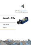
Hardware User Manual
EXT-SBC-i.MX51-DISP V1.2
Contact
Bluetechnix Mechatronische Systeme GmbH
Waidhausenstraße 3/19
A-1140 Vienna
AUSTRIA/EUROPE
[email protected]
http://www.bluetechnix.com
Document No.: 100-2523-1.3
Date: 2011-08-03
EXT-SBC-i.MX51-DISP_HUM_V1.2.docx
2
Table of Contents
i.MX Core Modules..................................................................................................................................................................................... 6
Core Module naming information ...................................................................................................................................................... 7
i.MX Development Boards ...................................................................................................................................................................... 8
1
2
Introduction ....................................................................................................................................................................................... 9
1.1
Overview ..................................................................................................................................................................................10
1.2
Key Features ...........................................................................................................................................................................10
1.3
Applications............................................................................................................................................................................10
General Description ......................................................................................................................................................................11
2.1
2.1.1
3
5
PCB Placement ......................................................................................................................................................................11
2.3
Mechanical Outline ..............................................................................................................................................................12
Specifications...................................................................................................................................................................................13
Digital I/O Characteristics ........................................................................................................................................13
3.1.2
Analog Inputs ...............................................................................................................................................................13
3.1.3
Maximum Ratings.......................................................................................................................................................13
3.1.4
ESD Sensitivity .............................................................................................................................................................14
Connector Description .................................................................................................................................................................15
4.1
Display Data Connector X1 (Toshiba LT084AC3711) .............................................................................................15
4.2
LVDS Backlight Supply Connector X2 (Toshiba LT084AC3711) .........................................................................15
4.3
Display Power Supply Connector X3 ............................................................................................................................16
4.4
Touch Panel Connector X4 (Toshiba LT084AC3711) ..............................................................................................16
4.5
Display Connector X5 (ET0500G0DH6) ........................................................................................................................16
4.6
Image Sensor Connector X13 (BLT-ISM-Connector) ...............................................................................................18
Support ..............................................................................................................................................................................................19
5.1
General Support....................................................................................................................................................................19
5.2
Board Support Packages ...................................................................................................................................................19
5.3
i.MX Software Support .......................................................................................................................................................19
5.3.2
5.4
5.4.1
Linux ................................................................................................................................................................................19
Win CE .............................................................................................................................................................................19
i.MX Design Services ..........................................................................................................................................................19
®
Upcoming Products and Software Releases ....................................................................................................19
Ordering Information ...................................................................................................................................................................20
6.1
7
Electrical Specifications......................................................................................................................................................13
3.1.1
5.3.1
6
Powering ........................................................................................................................................................................11
2.2
3.1
4
Functional Description .......................................................................................................................................................11
Predefined mounting options for EXT-SBC-i.MX51-DISP .....................................................................................20
Dependability ..................................................................................................................................................................................21
EXT-SBC-i.MX51-DISP_HUM_V1.2.docx
3
7.1
8
Product History ...............................................................................................................................................................................22
8.1
Version Information.............................................................................................................................................................22
8.2
Anomalies................................................................................................................................................................................22
9
10
A
MTBF ..........................................................................................................................................................................................21
Document Revision History .......................................................................................................................................................23
List of Abbreviations ................................................................................................................................................................24
List of Figures and Tables............................................................................................................................................................25
EXT-SBC-i.MX51-DISP_HUM_V1.2.docx
4
© Bluetechnix Mechatronische Systeme GmbH 2011
All Rights Reserved.
The information herein is given to describe certain components and shall not be considered as a guarantee of
characteristics.
Terms of delivery and rights of technical change reserved.
We hereby disclaim any warranties, including but not limited to warranties of non-infringement, regarding circuits,
descriptions and charts stated herein.
Bluetechnix makes and you receive no warranties or conditions, express, implied, statutory or in any
communication with you. Bluetechnix specifically disclaims any implied warranty of merchantability or fitness for a
particular purpose.
Bluetechnix takes no liability for any damages and errors causing of the usage of this board. The user of this board is
responsible by himself for the functionality of his application. He is allowed to use the board only if he has the
qualification. More information is found in the General Terms and Conditions (AGB).
Information
For further information on technology, delivery terms and conditions and prices please contact Bluetechnix
(http://www.bluetechnix.com).
Warning
Due to technical requirements components may contain dangerous substances.
EXT-SBC-i.MX51-DISP_HUM_V1.2.docx
5
i.MX Core Modules
CM-i.MX27-C-C-Q26S128F32N512
The Core Module CM-i.MX27 is powered by Freescales' SoC i.MX27 (ARM 926 core, up to 400MHz). It addresses
128MB DDR-RAM, has an onboard NOR-flash of 32MByte and a NAND-flash with 512MByte at a size of 55x45mm.
CM-i.MX31-C-C-Q26S128F40N128-E
The Core Module CM-i.MX31 is powered by Freescales' SoC i.MX31 (ARM1136JF-S core, up to 532MHz). It
addresses 128MB DDR-RAM, has an onboard NOR-flash of 40MByte and a NAND-flash with 128MByte at a size of
55x45mm. Core module is available as connector or BGA.
CM-i.MX53-C-I-Q24S1024F4N2048)
The Core Module CM-i.MX53 is powered by Freescales' SoC i.MX53 (ARM® Cortex™-A8, up to 1GHz). It addresses
1024MB DDR2-SDRAM, has an onboard NOR-flash of 4MByte and a NAND-flash with 2048MByte at a size of
80x45mm.
EXT-SBC-i.MX51-DISP_HUM_V1.2.docx
6
Core Module naming information
The idea is to put more Core Module specific technical information into the product name. New Core Module names
will have following technical information covered in their names.
•
Product Family,
•
CPU-Type,
•
Connection-Type,
•
Operating Temperature Range,
•
Crystal Frequency [MHz],
•
RAM [MB],
•
Flash [MB],
•
External Controllers
•
Optional
o
Special and/or
o
Former name
That expands of course the name but allows the customer to get the most important Core Module specific
information at the first sight. Have a look at the example below to get an idea of the new Core Module names.
Example CM-BF537-C-C-Q25S32F4 (CM-BF537E)
CM - BF537 - C - C - Q25
S32
F4 -
-
(CM-BF537E)
Product Family
Former name
CM = Core Module
Special
SBC = Single Board Computer
Custom Core Modules or specials
CPU-Type
uC = uclinux
Equals the name of CPU
Extra controllers mounted
Connection-Type
E = Ethernet
A = BGA
U = USB
B = Border pad
Flash [MB]
C = Connector
F = NOR Flash [MB]
S = SSpecial
N = NAND Flash [MB]
Operating Temperature Range
RAM
A = Automotive
(-40° to +125°)
S = SDRAM [MB]
C = Commercial
(0° to +70°)
I = Industry
(-40° to +85°)
Crystal Frequency
Notation: QXX[MHz]
EXT-SBC-i.MX51-DISP_HUM_V1.2.docx
7
i.MX Development Boards
DEV-i.MX27
The DEV-i.MX27 development board is an extendable development platform for the CM-i.MX27 processor modules.
With display connector and keypad it can be used as a reference design for a low power mobile handheld device
powered by a single Lithium Ion battery. The development board provides all interfaces of the connector version on
dedicated expansion connectors. Extender boards can be plugged on top of the development board in order to
enable additional interfaces.
DEV-iMX31
The DEV-i.MX31 Development Board is an extendable development platform for the CM-i.MX31 processor module.
With display connector and keypad it can be used as a reference design for a low power mobile handheld device
powered by a single Lithium Ion battery. The development board provides all interfaces of the connector version on
dedicated expansion connectors. Extender boards can be plugged on top of the development board in order to
enable additional interfaces.
SBC-i.MX51-S-C-Q24S512N2048
The Single-Board Computer SBC-i.MX51 is based on Freescale’s high-performance i.MX51 mobile platform,
incorporating an ARM Cortex-A8 CPU, an Image Processing Unit (IPUv3EX), a Video Processing Unit (VPU) and a
Graphical Processing Unit (GPU). The IPUv3EX provides comprehensive support for connectivity to displays and
cameras. The VPU supports hardware encoding and decoding of MPEG-4, H.263, H.264 and many more standards.
The GPU serves 3D and 2Dacceleration in hardware. The board‘s memory capabilities (NAND Flash, DDR2) and
numerous interfaces like Ethernet, HDMI,4xUSB and USB-OTG turn the SBC-i.MX51 into the ultimate development
board for future high-end embedded devices.
DEV-i.MX53
The DEV-i.MX53 development board is an extendable development platform for the CM-i.MX53 processor module.
The development board provides all interfaces of the connector version (Ethernet, HDMI,4xUSB and USB-OTG) on
dedicated extender connectors. Extender boards can be plugged on top of the development board in order to
enable additional interfaces.
Extender boards
Extender boards (EXT-SBC-i.MX51-) are expanding the development board SBC-i.MX51 by several interfaces and
functionalities. Targeted application areas are: audio/video processing, security and surveillance, Ethernet access,
positioning, automation and control, experimental development and measuring.
Note! Bluetechnix is offering tailored board developments as well.
EXT-SBC-i.MX51-DISP_HUM_V1.2.docx
8
1 Introduction
The EXT-SBC-i.MX51-DISP is a pluggable extender board for the SBC-i.MX51. It offers a display and a camera
interface (BLT-ISM-Connector) for the SBC-i.MX51. It is a low cost extender board designed for audiovisual systems
e.g. HMI, touch-control, interactive systems etc
Figure 1-1: Connected EXT-SBC-i.MX51-DISP on SBC-i.MX51
EXT-SBC-i.MX51-DISP_HUM_V1.2.docx
9
1.1
Overview
EXT-SBC-i.MX51-DISP
LVDS Display Connector
TFT Connector
Touch Pane Connector
LVDS Backlight
Supply Connector
LVDS Transmitter
BLT-ISM-Connector
Figure 1-2: Main components of EXT-SBC-i.MX51-DISP
1.2
Key Features
•
•
•
TFT Connector
o
40 pin ZIF connector
o
Various EDT displays available (3,5” to 7”; 320x240 to 800x480)
LVDS Connector
o
30 pin connector
o
Supports Toshiba LT084AC3711 LVDS display
LVDS Transmitter
o
•
Touch Panel Connector
o
•
•
1.3
National Semiconductor DS90C365
4 pin Connector for connection of a resistive Touch Panel
Power Supply
o
LVDS Backlight supplied via separate external power supply (not included)
o
EXT-SBC-i.MX51-DISP is powered via SBC-i.MX51
Camera Connector (BLT-ISM-Connector)
o
30 pin ZIF connector
o
Compatible with all Bluetechnix Image Sensor Modules
Applications
•
Rapid prototyping
•
POS terminals
•
Automation and control systems
•
Graphical User Interfaces
EXT-SBC-i.MX51-DISP_HUM_V1.2.docx
10
2 General Description
2.1
2.1.1
Functional Description
Powering
The EXT-SBC-i.MX51-DISP is supplied by the SBC-i.MX51. Please consider the chapter Electrical Specifications. If an
LVDS display is used (e.g. LT084AC3711) an external 12V power supply must be connected to the connector X3.
2.2
PCB Placement
Figure 2-1: Connector positions
EXT-SBC-i.MX51-DISP_HUM_V1.2.docx
11
2.3
Mechanical Outline
This section shows the position of all connectors and mounting holes. All dimensions are given in mm.
Figure 2-2: EXT-SBC-i.MX51-DISP top view
Figure 2-3: EXT-SBC-i.MX51-DISP bottom view
EXT-SBC-i.MX51-DISP_HUM_V1.2.docx
12
3 Specifications
3.1
Electrical Specifications
3.1.1
Digital I/O Characteristics
Parameter
High-Level Output Voltage
High-Level Output Voltage
Low-Level Output Voltage
High Level Output Current
Low-Level Output Current
High-Level Input Voltage
Low -Level Input Voltage
High -Level Input Voltage
Low -Level Input Voltage
Power Domain
P_VIOHI
P_SW4
all domains
all domains
all domains
P_VIOHI
P_VIOHI
P_SW4
P_SW4
Symbol
Voh
Voh
Vol
Ioh
Iol
Vih
Vil
Vih
Vil
Min
2.625
1.65
1.9
1.9
1.95
0
1.26
0
Typ.
2.775
1.8
-
Max
3.075
2.1
0.15
6.6
6.6
2.775
0.83
1.8
0.54
Unit
V
V
V
mA
mA
V
V
V
V
Table 3-1: Digital IO characteristics
3.1.2
Analog Inputs
Parameter
Resolution
Conversion Current
Conversion Core Input Voltage
Conversion Time Per Channel
Symbol
Min
Ic
Vin
tc
0
Typ.
10
1
-
Max
2.4
10
Unit
Bit
mA
V
µs
Table 3-2: ADC characteristics
3.1.3
Maximum Ratings
Stressing the device above the rating listed in the absolute maximum ratings table may cause permanent damage
to the device. These are stress ratings only. Operation of the device at these or any other conditions greater than
those indicated in the operating sections of this specification is not implied. Exposure to absolute maximum rating
conditions for extended periods may affect device reliability.
Symbol
VIO
VLED
IOH /IOL
TAMB
TSTO
TSLD
φAMB
Parameter
Input or output voltage
Backlight supply voltage
Current per pin
Ambient temperature
Storage temperature
Solder temperature for 10 seconds
Relative ambient humidity
Min
-0.5
0
0
-20
-55
Max
3.6
20
10
70
100
260
90
Unit
V
V
mA
°C
°C
°C
%
Table 3-3: Absolute maximum ratings
EXT-SBC-i.MX51-DISP_HUM_V1.2.docx
13
3.1.4
ESD Sensitivity
ESD (electrostatic discharge) sensitive device. Charged devices and circuit boards can
discharge without detection. Although this product features patented or proprietary
protection circuitry, damage may occur on devices subjected to high energy ESD.
Therefore, proper ESD precautions should be taken to avoid performance degradation or
loss of functionality.
EXT-SBC-i.MX51-DISP_HUM_V1.2.docx
14
4 Connector Description
4.1
Display Data Connector X1 (Toshiba LT084AC3711)
Pin No.
1
2
3
4
5
6
7
8
9
10
11
12
13
14
15
16
17
18
19
20
21
22
23
24
25
26
27
28
29
30
Signal Name
NC
NC
P_3V3
GND
TxCLK_N
TxCLK_P
P_3V3
GND
Tx0_N
Tx0_P
Tx1_N
Tx1_P
Tx2_N
Tx2_P
NC
NC
NC
NC
NC
NC
NC
NC
NC
NC
NC
NC
P_3V3
GND
NC
NC
Type
NC
NC
PWR
PWR
O
O
PWR
PWR
O
O
O
O
O
O
NC
NC
NC
NC
NC
NC
NC
NC
NC
NC
NC
NC
PWR
PWR
NC
NC
Power Domain
P_3V3
GND
P_3V3
P_3V3
P_3V3
GND
P_3V3
P_3V3
P_3V3
P_3V3
P_3V3
P_3V3
P_3V3
GND
Description
Not Connected
Not Connected
Display Power Supply
Power Ground
LVDS clock
LVDS clock
Display Power Supply
Power Ground
LVDS Channel 0
LVDS Channel 0
LVDS Channel 1
LVDS Channel 1
LVDS Channel 2
LVDS Channel 2
Not Connected
Not Connected
Not Connected
Not Connected
Not Connected
Not Connected
Not Connected
Not Connected
Not Connected
Not Connected
Not Connected
Not Connected
Display Power Supply
Power Ground
Not Connected
Not Connected
Table 4-1: Display Data Connector description (X1)
4.2
LVDS Backlight Supply Connector X2 (Toshiba LT084AC3711)
Pin No.
1
2
3
4
5
6
Signal Name
12V
12V
GND
GND
LVDS-nRESET
PWM1
Type
PWR
PWR
PWR
PWR
O
O
Power Domain
12V
12V
GND
GND
P_3V3
P_VIOHI
Description
Display Power Supply
Display Power Supply
Power Ground
Power Ground
Display ON/OFF
PWM1 Output
Table 4-2: Display Power Connector description (X2)
EXT-SBC-i.MX51-DISP_HUM_V1.2.docx
15
4.3
Display Power Supply Connector X3
Pin No.
1
2
3
Signal Name
12V
NC
GND
Type
PWR
NC
PWR
Power Domain
V_LED
GND
Description
External Backlight Power Supply
Not Connected
External Power Ground
Figure 4-1: Display Power Supply Connector description (X3)
4.4
Touch Panel Connector X4 (Toshiba LT084AC3711)
Pin No.
1
2
3
4
Signal Name
ADIN1
ADIN2
ADIN3
ADIN4
Type
AI
AI
AI
AI
Description
Touch Panel XR Terminal
Touch Panel YU Terminal
Touch Panel XL Terminal
Touch Panel YD Terminal
Figure 4-2: Touch Panel Connector description (X4)
4.5
Display Connector X5 (ET0500G0DH6)
Pin No.
1
2
3
4
5
6
7
8
9
10
11
12
13
14
15
16
17
18
19
20
21
22
23
24
25
26
27
28
29
30
Signal Name
DISP.nRESET
GND
DISP2.D4
DISP2.D3
DISP2.D2
DISP2.D1
DISP2.D0
DISP2.D4
GND
DISP2.D10
DISP2.D9
DISP2.D8
DISP2.D7
DISP2.D6
DISP2.D5
GND
DISP2.D15
DISP2.D14
DISP2.D13
DISP2.D12
DISP2.D11
DISP2.D15
GND
TFT.CLK
GND
TFT.HSYNC
TFT.VSYNC
TFT.DE
TFT.PWRCTRL
P_3V3
Type
O
PWR
O
O
O
O
O
O
PWR
O
O
O
O
O
O
PWR
O
O
O
O
O
O
PWR
O
PWR
O
O
O
O
PWR
Power Domain
P_3V3
GND
P_VIOHI
P_VIOHI
P_VIOHI
P_VIOHI
P_VIOHI
P_VIOHI
GND
P_VIOHI
P_VIOHI
P_VIOHI
P_VIOHI
P_VIOHI
P_VIOHI
GND
P_VIOHI
P_VIOHI
P_VIOHI
P_VIOHI
P_VIOHI
P_VIOHI
GND
P_VIOHI
GND
P_VIOHI
P_VIOHI
P_3V3
P_VIOHI
P_3V3
EXT-SBC-i.MX51-DISP_HUM_V1.2.docx
Description
Display Reset
Power Ground
Blue Data Bit 5
Blue Data Bit 4
Blue Data Bit 3
Blue Data Bit 2
Blue Data Bit 1
Blue Data Bit 0
Power Ground
Green Data Bit 5
Green Data Bit 4
Green Data Bit 3
Green Data Bit 2
Green Data Bit 1
Green Data Bit 0
Power Ground
Green Data Bit 5
Green Data Bit 4
Green Data Bit 3
Green Data Bit 2
Green Data Bit 1
Green Data Bit 0
Power Ground
Dot Data Clock
Power Ground
Horizontal Sync
Vertical Sync
Data Enable
Power Control
Power Supply
16
Pin No.
31
32
33
34
35
36
37
38
39
40
Signal Name
GND
GND
P_3V3
P_3V3
NC
PWM1
ADIN1
ADIN3
ADIN2
ADIN4
Type
PWR
PWR
PWR
PWR
NC
O
AI
AI
AI
AI
Power Domain
GND
GND
P_3V3
P_3V3
P_VIOHI
Description
Power Ground
Power Ground
Power Supply
Power Supply
Not Connected
Backlight Brightness Control
Touch Panel YU Terminal
Touch Panel XL Terminal
Touch Panel YD Terminal
Touch Panel XR Terminal
Figure 4-3: Display Connector description (X5)
EXT-SBC-i.MX51-DISP_HUM_V1.2.docx
17
4.6
Image Sensor Connector X13 (BLT-ISM-Connector)
Pin No.
SignalName
Type
Power Domain
Description
1
VCAMA
PWR
P_CAM_2V75
Camera Analog Voltage Supply
2
GND
PWR
GND
Power Ground
3
NC
NC
4
CAMCLK
O
P_SW4
Camera Master Clock
5
NRESET
O
P_SW4
Global Reset
6
SIO.C
O
P_SW4
Configuration Bus Clock Line
7
SIO.D
I/O
P_SW4
Configuration Bus Data Line
8
VCAMC
PWR
1V8
Camera Core Voltage Supply
9
GND
PWR
GND
Power Ground
10
CSI1.PCLK
I
P_SW4
Pixel Clock
11
CSI1.VSYNC
I
P_SW4
VSYNC
12
CSI1.HSYNC
I
P_SW4
HSYNC
13
GPIO3.5
O
P_SW4
Camera Trigger
14
STROBE
I
Strobe Signal from Camera (available only on solder pad)
15
NC
NC
Not Connected
16
NC
NC
17
CSI1.DO
I
P_SW4
Pixel Data
18
CSI1.D1
I
P_SW4
Pixel Data
19
VCAMIO
PWR
1V8
Camera IO Power Supply
20
GND
PWR
GND
Power Ground
21
CSI1.D2
I
P_SW4
Pixel Data
22
CSI1.D3
I
P_SW4
Pixel Data
23
CSI1.D4
I
P_SW4
Pixel Data
24
CSI1.D5
I
P_SW4
Pixel Data
25
GND
PWR
GND
Power Ground
26
CSI1.D6
I
P_SW4
Pixel Data
27
CSI1.D7
I
P_SW4
Pixel Data
28
CSI1.D8
I
P_SW4
Pixel Data
29
CSI1.D9
I
P_SW4
Pixel Data
30
CSI1.PWDN
O
P_SW4
Output Enable (Active Low)
Not Connected
Not Connected
Table 4-3: BLT-ISM-Connector interface description (X13)
EXT-SBC-i.MX51-DISP_HUM_V1.2.docx
18
5 Support
5.1
General Support
General support for products can be found at Bluetechnix’ support site https://support.bluetechnix.at/wiki
5.2
Board Support Packages
Board support packages, boot loaders and further software downloads can be downloaded at the products wiki
page at https://support.bluetechnix.at/wiki
5.3
5.3.1
i.MX Software Support
Linux
Linux BSP and images of derivates can be found at Bluetechnix’ support site https://support.bluetechnix.at/wiki at
the software section of the related product.
5.3.2
Win CE
WinCE is only supported on ARM platforms. Please contact Bluetechnix for support information.
5.4
i.MX® Design Services
Based on more than seven years of experience with Blackfin and i.MX, Bluetechnix offers development assistance as
well as custom design services and software development.
5.4.1
Upcoming Products and Software Releases
Keep up to date with all product changes, releases and
http://www.bluetechnix.com.
EXT-SBC-i.MX51-DISP_HUM_V1.2.docx
software
updates
of Bluetechnix at
19
6 Ordering Information
6.1
Predefined mounting options for EXT-SBC-i.MX51-DISP
Article Number
100-2523-1
100-9910-1
100-4110-2
Name
EXT-SBC-i.MX51-DISP
EDT-TFT-5.0"-WVGA-G-ET0500G0DH6
SBC-i.MX51-S-C-Q24S512N2048
(SBC-i.MX51)
Description
Display and camera extender board for SBC-i.MX51
EDT Display TFT 5.0" WVGA, 300cd/m² LED, TTL, touch
Single-Board Computer SBC-I.MX51 based on i.MX51
SoC
Table 6-1: Ordering information
NOTE:
Custom hard and software developments are available on request! Please contact Bluetechnix
([email protected]) if you are interested in custom hard- and software developments.
EXT-SBC-i.MX51-DISP_HUM_V1.2.docx
20
7 Dependability
7.1
MTBF
Please keep in mind that a part stress analysis would be the only way to obtain significant failure rate results,
because MTBF numbers just represent a statistical approximation of how long a set of devices should last before
failure. Nevertheless, we can calculate an MTBF of the development board using the bill of material. We take all the
components into account. The PCB and solder connections are excluded from this estimation. For test conditions
we assume an ambient temperature of 30°C of all development board components. We use the MTBF Calculator
from ALD (http://www.aldservice.com/) and use the reliability prediction MIL-217F2 Part Stress standard. Please get
in touch with Bluetechnix ([email protected]) if you are interested in the MTBF result.
EXT-SBC-i.MX51-DISP_HUM_V1.2.docx
21
8 Product History
8.1
Version Information
Version
1.2
1.1
8.2
Date
2011-05-30
2011-04-20
Changes
Changed layout of Image Sensor Connector X13
First release V1.1 of the Hardware.
Table 8-1: Overview product changes
Anomalies
Version
1.1
Date
2011-04- 20
Description
No anomalies reported yet.
Table 8-2: Overview product anomalies
EXT-SBC-i.MX51-DISP_HUM_V1.2.docx
22
9 Document Revision History
Version
3
2
1
Date
2011 08 03
2011 05 30
2011 04 20
Document Revision
Changed product photos
Update for Board Revision 1.2
First release V1.0 of the Document
Table 9-1: Revision History
EXT-SBC-i.MX51-DISP_HUM_V1.2.docx
23
10 List of Abbreviations
Abbreviation
ADI
AI
AMS
AO
CM
DC
DSP
eCM
EBI
ESD
GPIO
I
I²C
I/O
ISM
LDO
MTBF
NC
NFC
O
OS
PPI
PWR
RTOS
SADA
SD
SoC
SPI
SPM
SPORT
TFT
TISM
TSC
UART
USB
USBOTG
ZIF
Description
Analog Devices Inc.
Analog Input
Asynchronous Memory Select
Analog Output
Core Module
Direct Current
Digital Signal Processor
Enhanced Core Module
External Bus Interface
Electrostatic Discharge
General Purpose Input Output
Input
Inter-Integrated Circuit
Input/Output
Image Sensor Module
Low Drop-Out regulator
Mean Time Between Failure
Not Connected
NAND Flash Controller
Output
Operating System
Parallel Peripheral Interface
Power
Real-Time Operating System
Stand Alone Debug Agent
Secure Digital
System on Chip
Serial Peripheral Interface
Speech Processing Module
Serial Port
Thin-Film Transistor
Tiny Image Sensor Module
Touch Screen Controller
Universal Asynchronous Receiver Transmitter
Universal Serial Bus
USB On The Go
Zero Insertion Force
Table 10-1: List of abbreviations
EXT-SBC-i.MX51-DISP_HUM_V1.2.docx
24
A
List of Figures and Tables
Figures
Figure 1-1: Connected EXT-SBC-i.MX51-DISP on SBC-i.MX51 ................................................................................................................9
Figure 1-2: Main components of EXT-SBC-i.MX51-DISP ........................................................................................................................ 10
Figure 2-1: Connector positions ...................................................................................................................................................................... 11
Figure 2-2: EXT-SBC-i.MX51-DISP top view ................................................................................................................................................. 12
Figure 2-3: EXT-SBC-i.MX51-DISP bottom view ........................................................................................................................................ 12
Figure 4-1: Display Power Supply Connector description (X3) ........................................................................................................... 16
Figure 4-2: Touch Panel Connector description (X4) .............................................................................................................................. 16
Figure 4-3: Display Connector description (X5) ........................................................................................................................................ 17
Tables
Table 3-1: Digital IO characteristics ................................................................................................................................................................ 13
Table 3-2: ADC characteristics .......................................................................................................................................................................... 13
Table 3-3: Absolute maximum ratings.......................................................................................................................................................... 13
Table 4-1: Display Data Connector description (X1) ............................................................................................................................... 15
Table 4-2: Display Power Connector description (X2) ............................................................................................................................ 15
Table 4-3: BLT-ISM-Connector interface description (X13) ................................................................................................................... 18
Table 6-1: Ordering information ..................................................................................................................................................................... 20
Table 8-1: Overview product changes .......................................................................................................................................................... 22
Table 8-2: Overview product anomalies ...................................................................................................................................................... 22
Table 9-1: Revision History ................................................................................................................................................................................ 23
Table 10-1: List of abbreviations ..................................................................................................................................................................... 24
EXT-SBC-i.MX51-DISP_HUM_V1.2.docx
25