1
4 Connector Description
4.1
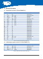
Display Data Connector X1 (Toshiba LT084AC3711)
Pin No.
1
2
3
4
5
6
7
8
9
10
11
12
13
14
15
16
17
18
19
20
21
22
23
24
25
26
27
28
29
30
Signal Name
NC
NC
P_3V3
GND
TxCLK_N
TxCLK_P
P_3V3
GND
Tx0_N
Tx0_P
Tx1_N
Tx1_P
Tx2_N
Tx2_P
NC
NC
NC
NC
NC
NC
NC
NC
NC
NC
NC
NC
P_3V3
GND
NC
NC
Type
NC
NC
PWR
PWR
O
O
PWR
PWR
O
O
O
O
O
O
NC
NC
NC
NC
NC
NC
NC
NC
NC
NC
NC
NC
PWR
PWR
NC
NC
Power Domain
P_3V3
GND
P_3V3
P_3V3
P_3V3
GND
P_3V3
P_3V3
P_3V3
P_3V3
P_3V3
P_3V3
P_3V3
GND
Description
Not Connected
Not Connected
Display Power Supply
Power Ground
LVDS clock
LVDS clock
Display Power Supply
Power Ground
LVDS Channel 0
LVDS Channel 0
LVDS Channel 1
LVDS Channel 1
LVDS Channel 2
LVDS Channel 2
Not Connected
Not Connected
Not Connected
Not Connected
Not Connected
Not Connected
Not Connected
Not Connected
Not Connected
Not Connected
Not Connected
Not Connected
Display Power Supply
Power Ground
Not Connected
Not Connected
Table 4-1: Display Data Connector description (X1)
4.2
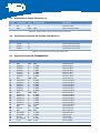
LVDS Backlight Supply Connector X2 (Toshiba LT084AC3711)
Pin No.
1
2
3
4
5
6
Signal Name
12V
12V
GND
GND
LVDS-nRESET
PWM1
Type
PWR
PWR
PWR
PWR
O
O
Power Domain
12V
12V
GND
GND
P_3V3
P_VIOHI
Description
Display Power Supply
Display Power Supply
Power Ground
Power Ground
Display ON/OFF
PWM1 Output
Table 4-2: Display Power Connector description (X2)
EXT-SBC-i.MX51-DISP_HUM_V1.2.docx
15