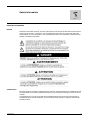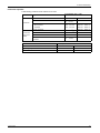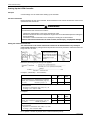
1
1743233 03/2009 ® TeSys U LUTM Controller User's Manual 1743233 03/2009 www.schneider-electric.com Schneider Electric assumes no responsibility for any errors that may appear in this document. If you have any suggestions for improvements or amendments or have found errors in this publication, please notify us. No part of this document may be reproduced in any form or by any means, electronic or mechanical, including photocopying, without express written permission of Schneider Electric. All pertinent state, regional, and local safety regulations must be observed when installing and using this product. For reasons of safety and to help ensure compliance with documented system data, only the manufacturer should perform repairs to components. When devices are used for applications with technical safety requirements, the relevant instructions must be followed. Failure to use Schneider Electric software or approved software with our hardware products may result in injury, harm, or improper operating results. Failure to observe this information can result in injury or equipment damage. © 2009 Schneider Electric. All rights reserved. 2 1743233 03/2009 Table of Contents Safety Information . . . . . . . . . . . . . . . . . . . . . . . . . . . . . . . . . . . . . . . . . . . . About the Book . . . . . . . . . . . . . . . . . . . . . . . . . . . . . . . . . . . . . . . . . . . . . . . Chapter 1 LUTM Controller Setup. . . . . . . . . . . . . . . . . . . . . . . . . . . . . . . . . . . . . . . . . 5 7 9 Safety Instructions . . . . . . . . . . . . . . . . . . . . . . . . . . . . . . . . . . . . . . . . . . . . . . . . . . . . . . . . . . Presentation of the LUTM Controller. . . . . . . . . . . . . . . . . . . . . . . . . . . . . . . . . . . . . . . . . . . . . Description of the LUTM Controller . . . . . . . . . . . . . . . . . . . . . . . . . . . . . . . . . . . . . . . . . . . . . . Presentation of the Power Unit . . . . . . . . . . . . . . . . . . . . . . . . . . . . . . . . . . . . . . . . . . . . . . . . . Assembly of the LUTM controller . . . . . . . . . . . . . . . . . . . . . . . . . . . . . . . . . . . . . . . . . . . . . . . Connection . . . . . . . . . . . . . . . . . . . . . . . . . . . . . . . . . . . . . . . . . . . . . . . . . . . . . . . . . . . . . . . . Starting Up the LUTM Controller . . . . . . . . . . . . . . . . . . . . . . . . . . . . . . . . . . . . . . . . . . . . . . . . 10 11 12 16 17 18 22 Chapter 2 Operation of the LUTM controller . . . . . . . . . . . . . . . . . . . . . . . . . . . . . . . . 25 Operating Modes. . . . . . . . . . . . . . . . . . . . . . . . . . . . . . . . . . . . . . . . . . . . . . . . . . . . . . . . . . . . Fault Management and Reset Mode . . . . . . . . . . . . . . . . . . . . . . . . . . . . . . . . . . . . . . . . . . . . . 26 32 Chapter 3 Technical characteristics of the LUTM controller . . . . . . . . . . . . . . . . . . . 37 Technical Characteristics . . . . . . . . . . . . . . . . . . . . . . . . . . . . . . . . . . . . . . . . . . . . . . . . . . . . . 37 Glossary . . . . . . . . . . . . . . . . . . . . . . . . . . . . . . . . . . . . . . . . . . . . . . . . . . . . . . . Index . . . . . . . . . . . . . . . . . . . . . . . . . . . . . . . . . . . . . . . . . . . . . . . . . . . . . . . 39 41 1743233 03/2009 3 4 1743233 03/2009 Safety Information § Important Information NOTICE Read these instructions carefully, and look at the equipment to become familiar with the device before trying to install, operate, or maintain it. The following special messages may appear throughout this documentation or on the equipment to warn of potential hazards or to call attention to information that clarifies or simplifies a procedure. PLEASE NOTE Electrical equipment should be installed, operated, serviced, and maintained only by qualified personnel. No responsibility is assumed by Schneider Electric for any consequences arising out of the use of this material. A qualified person is one who has skills and knowledge related to the construction and operation of electrical equipment and the installation, and has received safety training to recognize and avoid the hazards involved. 1743233 03/2009 5 6 1743233 03/2009 About the Book At a Glance Document Scope This manual describes the setup, functions and operation of the TeSys U LUTM controller. Area of application: installers, design office, maintenance staff. Validity Note The availability of some functions depends on the TeSys U LUTM controller software version. Related Documents Title of Documentation Reference Number LU•B/LU•S• TeSys U Starters - Instruction Sheet 1629984 LUTM• Tesys U Controller - Instruction Sheet 1743236 LUCM/LUCMT Multifunction Control Units - User’s Manual 1743237 LUCM/LUCMT/LUCBT/LUCDT Control Units - Instruction Sheet AAV40504 You can download these technical publications and other technical information from our website at www.schneider-electric.com. User Comments We welcome your comments about this document. You can reach us by e-mail at [email protected]. 1743233 03/2009 7 8 1743233 03/2009 LUTM Controller Setup 1743233 03/2009 LUTM Controller Setup 1 What's in this Chapter? This chapter contains the following topics: Topic 1743233 03/2009 Page Safety Instructions 10 Presentation of the LUTM Controller 11 Description of the LUTM Controller 12 Presentation of the Power Unit 16 Assembly of the LUTM controller 17 Connection 18 Starting Up the LUTM Controller 22 9 LUTM Controller Setup Safety Instructions General Instructions WARNING HAZARDOUS OPERATION These devices must be installed, configured and used by qualified staff only. Users must follow all current instructions, standards and regulations. Check the function settings before starting the motor. Do not downgrade or modify these devices. Failure to follow these instructions can result in death, serious injury, or equipment damage. WARNING SETTING ERROR Data relating to motor-starter states and load current values must not be used to control safety devices and emergency stops. Check the function settings before starting the motor. Failure to follow these instructions can result in death, serious injury, or equipment damage. 10 1743233 03/2009 LUTM Controller Setup Presentation of the LUTM Controller Aim of the Product When used with a short-circuit protection device and a contactor, the LUTM controller creates a motor starter that provides protection against overloads and permits control of motor starter functions. Functions include: Direct control via its output relays of the coils of reversing and non-reversing contactors up to 250 kW (F500) Control of the coils of reversing and non-reversing contactors above 250 kW using an interface relay between the controller output relays and the contactor coils Monitoring and protection of nominal currents up to 800 A NOTE: In an installation containing TeSys U starter-controllers and TeSys U controllers, motor-starter management is identical from the point of view of the PLC. Conditions of Use Irrespective of the nominal current value of the motor it is supposed to control, the LUTM controller is always used with external current transformers in which: The secondary is at 1 A nominal. The primary is selected according to the motor nominal current. Typical Composition Typical composition of a motor-starter unit 1743233 03/2009 A TeSys U controller B Power unit C Current transformers 11 LUTM Controller Setup Description of the LUTM Controller The LUTM controller consists of: A controller base An advanced or multifunction control unit And, if required, a function module or communication module LUTM••BL Controller Base LUCBT1BL or LUCDT1BL Advanced Control Unit LUCMT1BL Multifunction Control Unit Module (Optional) Function module: - LUFV2 motor-load indication - LUFW10 thermal-overload alarm Communication module: - Modbus LULC032-033 - CANopen LULC08 - DeviceNet LULC09 - Advantys STB LULC15 Configuration There are two main configurations: Controller without communication module (Protection of a motor > 32A, stand-alone operation) Controller with communication module (Control and protection of a motor in a control panel) Composition of a Controller WITHOUT Communication Five possible combinations. LUTM••BL Controller Base Control Unit Advanced LUCBT1BL/LUCDT1 BL Control Unit Multifunction LUCMT1BL ----- 12 Advanced LUCBT1BL/LUCDT1BL Multifunction LUCMT1BL Function module (optional) --- LUFW10 LUFV2 1743233 03/2009 LUTM Controller Setup Composition of a Controller WITH Communication Two possible combinations. LUTM••BL Controller Base Control Unit Advanced LUCBT1BL/LUCDT1BL Multifunction LUCMT1BL LULC• communication module LUTM••BL Controller Base There are two controller bases depending on the model of contactor to be controlled: LUTM10BL and LUTM20BL. Table of LUTM/contactor combinations. LUTM10BL LUTM20BL Voltage Contactor Voltage Contactor 24 <=> 250 V TeSys d 24 <=> 250 V TeSys d 24 V TeSys d 09 <=> 95 24 V TeSys d 09 <=> 95 110 <=> 250 V TeSys f Composition of the LUTM••BL Controller Base Components in the controller base. Reset button and LEDs 1743233 03/2009 1 Fixed terminal: connection of the current-transformer secondaries 2 Slot for control unit 3 Slot for module (optional) 4 Removable terminals: connection of the power supply and the inputs 5 Removable terminal: connection of the outputs 13 LUTM Controller Setup LEDs on the LUTM••BL Controller Base Description of the various states of the LEDs on the controller base. Light-Emitting Diodes Green "24V " LED Red "FAULT" LED On Off Flashing Off Normal operation On or off Possible fault See State of the LEDs on the Controller Base, page 33 On Contact for output 13 "closed" Off Off Possible fault See State of the LEDs on the Controller Base, page 33 On Contact for output 23 "closed" Light-Emitting Diodes Green "13" LED Green "23" LED Comment Comment LUC•T Advanced Control Unit Functions performed by the advanced control unit. Protection: - against overloads, class 10 (LUCBT1BL) or 20 (LUCDT1BL) - against loss of phase and phase imbalance Current setting on front panel Thermal trip test Reset: - manual - remote or automatic in conjunction with a function module or a communication module Display (motor load) with a function module or a communication module Alarm: with a function module (e.g., LUFW10) Setting the Advanced Control Unit, page 22 LUCMT Multifunction Control Unit Functions performed by the multifunction control unit. Protection Alarm Diagnostics These three functions can be configured and monitored. Reset: - manual - remote or automatic Refer to the documentation for this product. LUFW10 Function Module Functions performed by the "Alarm on thermal overload" function module. Determination of the motor thermal state Alarm signaling for: - improving the performance of the controlled motor - anticipating complete stop due to a thermal overload Avoiding, by load shedding, interruptions in use due to tripping on overloads. All the data processed by this module can be accessed on discrete contacts. NOTE: Can only be used with the advanced control unit. 14 1743233 03/2009 LUTM Controller Setup LUFV2 Function Module Functions performed by the "Indication of the motor load (analog)" function module. Determination of the state of the motor load (I mean/FLA) - I mean = mean value of the rms currents in all 3 phases - FLA = value of the setting current It delivers an analog signal of 4 to 20 mA (0% to 200%) proportional to the motor load. NOTE: Can be used with an advanced or multifunction control unit. LULC• Communication Module Functions performed by the communication module. Network connection of the LUTM controller Alarm Diagnostics Processed data is exchanged via the serial link. Refer to the documentation for this product. The protection and control data available depend on the control unit with which the communication module is used. Control Unit 1743233 03/2009 Data - Commands Advanced LUCBT/CDT1BL Multifunction LUCMT1BL Start and stop commands X X Status (ready, running, fault condition) X X Alarm X X Automatic reset and remote reset via the bus X X Indication of the motor load X X Differentiation of faults X Remote parameter setting and viewing of all functions X "Statistics" function X "Monitoring" function X 15 LUTM Controller Setup Presentation of the Power Unit Description The power unit consists of: Three current transformers (see Transformer Characteristics, page 19): - Supplied by Schneider Electric ==> LUTC••01 - Other suppliers ==> characteristics to be adhered to A contactor A short-circuit protection device NOTE: In combination with LUTC••01 current transformers, the LUTM••BL controller base must only be used with motors from 0.75 kW to 450 kW/800 A nominal. Current Transformer and Contactor Product reference (Schneider Electric) for the current transformers and contactor. Current transformers 3 * LUTC••01 Contactor Non-reversing LC1•••• Reversing LC2•••• Protection Against Short-Circuits Protection against short-circuits is provided by one of the following: Magnetic circuit-breaker Fuses WARNING VALIDITY OF THERMAL PROTECTION Thermal-magnetic motor circuit-breakers are prohibited since they incorporate an overload protection function, which would duplicate that in the modules and interfere with the control-unit analysis. Failure to follow these instructions can result in death, serious injury, or equipment damage. Protection Via a Magnetic Circuit-Breaker Magnetic circuit-breaker Power (1) Circuit-Breaker P (kW) Ie (A) Reference Rating (A) FLAm (A) (2) 0.75 to 400 2 to 710 NS•••H 2.5 to 800 25 to 8000 0.75 to 15 2 to 32 GV2-L2• 2 to 32 33 to 420 (1) Standard power ratings for 50/60 Hz 400/415 V 3-phase motors (2) FLAm = Magnetic circuit-breaker setting current Protection with Fuses Fuses with disconnect switch. Power (1) aM fuse Disconnect Switch P (kW) Ie (A) Size Rating (A) Reference 0.75 to 315 2 to 555 10.3x38 to T3 4 to 630 GS1-DD to GS1-S Fuses with holder. Power (1) aM fuse P (kW) Ie (A) 0.75 to 15 0.75 to 55 Holder Size Rating (A) Reference 2 to 32 10.3x38 4 to 32 LS1• 2 to 105 14x51 to 22x58 4 to 125 GK1• (1) Standard power ratings for 50/60 Hz 400/415 V 3-phase motors 16 1743233 03/2009 LUTM Controller Setup Assembly of the LUTM controller Principle The function module or communication module (optional) is installed in the controller base beneath the control unit, which locks it in position. Installation You must proceed as follows when assembling the controller: Step Action 1 Install the module (optional): Function module: - LUFW10 thermal-overload alarm - LUFV2 motor-load indication LULC• communication module 2 Install the control unit: Advanced LUCBT1BL/LUCDT1BL Multifunction LUCMT1BL Location of the components. 1743233 03/2009 17 LUTM Controller Setup Connection Connecting the Transformers WARNING LOSS OF THERMAL PROTECTION Switch off the power supply before disconnecting the current transformers. Do not disconnect the current transformers during operation. Failure to follow these instructions can result in death, serious injury, or equipment damage. Disconnecting the current transformers during use will disable controller protection. The three current transformers are connected to the fixed terminals. These terminals can be used to measure the current in all three phases: 2 x 3 terminals for connecting the current-transformer secondaries placed in each of the 3 power phases: L1 - L2 - L3 One ground terminal for connecting the center point NOTE: Use of the ground terminal is not compulsory. Transformers to be Used In order to operate correctly, the LUTM controller requires an accurate current value received from the current-transformer secondary. It is essential to use "motor protection" transformers, which accept up to 10 times the nominal current with accuracy of at least 5% (5P10). NOTE: Typical "measurement" type transformers are prohibited as their operating range is too limited and therefore they are not sufficiently accurate. 18 1743233 03/2009 LUTM Controller Setup Transformer Characteristics If the transformer supplier is Telemecanique: the references to be ordered are as follows. Motor In Primary (A) Secondary (A) No. of Pass(es) Reference 3.5 to 10.5 30 1 3 LUTC0301 5.2 to 16 30 1 2 LUTC0301 10.5 to 32 30 1 1 LUTC0301 17.5 to 3 50 1 1 LUTC0501 35 to 105 100 1 1 LUTC1001 70 to 210 200 1 1 LUTC2001 140 to 420 400 1 1 LUTC4001 280 to 840 800 1 1 LUTC8001 Illustration showing how current transformers are set up. 1 Pass 2 Passes All three CTs must be connected in the same way in order to ensure identical relative polarity: the cable must be routed in the same direction for the three current transformers (entering via the side marked P1K-H1). Connecting the Power Supply and the Control Inputs In order to operate, the LUTM controller must be powered by a 24 V source. Both these terminal blocks are removable. 2 terminals for 24 V power supply 1 terminal for the power-supply connection to the inputs 10 terminals for the control inputs NOTE: The LUTM controller is rated IP20 or higher. However, for best protection from electric shock and consistent product performance, do not touch the connections during product operation. The 24 V to: is distributed internally in order to supply power directly (without additional customer wiring) The advanced (LUCBT or LUCDT) or multifunction (LUCMT) control unit The LULC• communication module NOTE: Power is supplied to the control unit, the function module and the communication module automatically once they are installed in the controller base. 1743233 03/2009 19 LUTM Controller Setup Particular Feature of the LULC• Communication Module In "remote via the bus" or "mixed" mode. Example of connection of the 24 V supply to an LULC033 module: power The use of outputs OA1, OA3 and LO1 on an LULC• communication module requires a 24 V power supply connected to the controller. Inputs LI1 and LI2 do not require an external power supply. Use a cable shorter than 5 cm to connect the LUTM controller’s 24 V(-) to the LULC• communication module’s 24 V(-). Do not connect the LULC• communication module’s AUX 24 V (+) when the module is mounted on the LUTM controller. Connecting the Outputs Relay outputs - 24 V or 24 V to 250 V . NOTE: The contacts (95 - 96) and (97 - 98) are shown with the controller powered up, input I.6 at 1 and in the absence of any fault condition. This terminal is removable. 2 NO contacts (13 and 23) for controlling the contactors 1 NO contact (95 - 96) and NC contact (97 - 98): "Any fault" relay 1 NC contact (05 - 06): "Control-unit fault" relay. State of the Output Relays Before power-up. Output Relay Status 05 - 06 "Control unit fault" Closed 95 - 96 97 - 98 After power-up (24 V "Any fault" Open Closed ) with input I.6 at 1 and in the absence of any fault condition. Output Relay Status 05 - 06 "Control unit fault" Closed 95 - 96 97 - 98 "Any fault" Closed Open NOTE: See also Fault Management and Reset Mode, page 32. 20 1743233 03/2009 LUTM Controller Setup Connection Capacities Table showing conductor cross-sections to be used. Connection 1 conductor 2 conductors (same crosssection) 1743233 03/2009 Cross-Section (min. - max.) Type of Conductor Solid conductor 0.2 ... 2.5 mm2 AWG 24 ... AWG 12 Stranded conductor 0.2 ... 2.5 mm2 AWG 24 ... AWG 12 Stranded conductor with cable end: - Non-insulated - Insulated 0.25 ... 2.5 mm2 0.25 ... 2.5 mm 2 AWG 24 ... AWG 12 AWG 24 ... AWG 12 2 solid conductors 0.2 ... 1 mm2 AWG 24 ... AWG 18 2 stranded conductors 0.2 ... 1.5 mm2 AWG 24 ... AWG 16 2 stranded conductors with cable end, non-insulated 0.25 ... 1 mm2 AWG 24 ... AWG 18 2 stranded conductors with TWIN cable end, insulated AWG 20 ... AWG 16 0.5 ... 1.5 mm2 Connectors 6, 7 and 8 pts Pitch 5 mm Tightening torque 0.5/0.6 N.m. 4.43/5.31 lb.in. Flat screwdriver 3.5 mm 0.14 in. 0.2 in. 21 LUTM Controller Setup Starting Up the LUTM Controller Principle Certain settings must be made before starting up the controller. Current Transformers Before attempting to start up the controller, the characteristics of the current transformers used must be specified for each control unit. WARNING INADEQUATE THERMAL PROTECTION The transformer ratio must be set in order to: Indicate the characteristics of the current transformers used Determine the default value of the adjustment range for the current threshold required for setting the thermal protection Connect the current transformers to the LUTM prior to starting the LUTM controller Failure to follow these instructions can result in death, serious injury, or equipment damage. Setting the Advanced Control Unit The characteristic of the current transformers used must be indicated before any attempt to power up the controller, by setting the thermal protection on the front panel of the advanced control unit: range from 35% to 105%. A set of 8 self-adhesive labels is supplied with each TeSys U controller, enabling the user to set the current value directly in Amps. Example .........................> Method of calculating the percentage to be applied: Example 1 (I secondary = 1A in all cases): 3 kW motor at 400 V motor In of 6.5 A Motor In Primary (A) No. of passes Current transformer (CT) selected from one of the 2 options (see Transformer Characteristics, page 19): CT = 30:1 Number of passes = 2 3.5 to 10.5 30 3 5.2 to 16 30 2 Calculation to be performed to determine the percentage to be applied in order to set the thermal protection Equivalent CT transformer ratio = 30/(1 x 2) = 15 % setting = (6.5 x 100)/15 = 43% Example 2: 90 kW motor at 400 V motor In of 165 A Motor In Primary (A) No. of passes Current transformer (CT) selected from one of the 2 options (see Transformer Characteristics, page 19): CT = 200:1 Number of passes = 1 70 to 210 200 1 140 to 420 400 1 Calculation to be performed to determine the percentage to be applied in order to set the thermal protection Equivalent CT transformer ratio = 200/(1 x 1) = 200 % setting = (165 x 100)/200 = 83% No. of passes = Number of pass(es) in the current-transformer primary. 22 1743233 03/2009 LUTM Controller Setup Setting the LUCMT Multifunction Control Unit The characteristic of the current transformers used is selected when the controller is first powered up in the "CT_Ratio" function of the "Configure" menu. The protection, alarm and diagnostic functions can be configured and monitored: Locally via the built-in keypad and display unit Remotely via the Modbus RS 485 RJ-45 communication port, using: A PC equipped with PowerSuite software (VW3A8104) A PDA equipped with PowerSuite software (VW3A8104) An XBT NU 400 operator dialog terminal mounted on a cabinet door Refer to the documentation for this product. 1743233 03/2009 23 LUTM Controller Setup 24 1743233 03/2009 Operation of the LUTM controller 1743233 03/2009 Operation of the LUTM controller 2 This chapter describes the operating modes in each of the two configurations (with or without the communication module) and the inputs used. Operation also covers the management of faults and the various reset modes. What's in this Chapter? This chapter contains the following topics: Topic 1743233 03/2009 Page Operating Modes 26 Fault Management and Reset Mode 32 25 Operation of the LUTM controller Operating Modes Presentation Operating modes and inputs used for each configuration. Configuration Operation Inputs used Without communication module "Local" mode I.1, I.2, I.6 + I.5 With communication module "Local" mode (default) "Mixed" mode (if I.10 = 1) I.1, I.2, I.3, I.4, I.6 + I.10 + I.5 "Remote via the bus" mode. "Mixed" mode (if I.10 = 0) I.1, I.2, I.3, I.4, I.6 + I.10 + I.5 I.7, I.8 and I.9 I.7, I.8 and I.9 NOTE: The operating mode ("local", "remote via the bus" or "mixed") must be configured in the communication module. (Refer to the documentation for this product) In the PLC, the user can read the word reflecting the state of the I/O at any time. Inputs Used WITHOUT a Communication Module 4 inputs are used in a configuration without a communication module. Input I.1 I.2 Function Output Comment Each input controls the output relay. 13 = state of the input 23 = state of the input Note: If the voltage is too low, the output opens. An external fault or control unit fault has no effect on the state of these relays. I.5 RST (Reset) This input is dedicated. It is used for remote "manual" reset of the controller following a control unit fault. --- Using a reset button on the front of the rack or control panel I.6 SF (System Fault) This input is dedicated. It is used to feed back trip data from an additional protection device to the controller. This input must be --connected to 24 V(+) to enable LUTM controller operation in the absence of a data signal from an additional protection device. Example: Receipt of the data provided by the "Trip" NC contact: => For a circuit-breaker, a sensor relay, a voltage relay => For a string of these contacts NOTE: Inputs I.3, I.4and I.7 to I.10 are only used in a configuration with a communication module. 26 1743233 03/2009 Operation of the LUTM controller Examples of Applications Machines with manual local control. 2-wire control by the controller I/O (non-reversing) 1 2 3 4 Channel 1 Channel 2 Any fault Control unit fault 1 2 3 4 Channel 1 Channel 2 Any fault Control unit fault External fault 2-wire control by the controller I/O (reversing) 5 3-wire control by the controller I/O (reversing) 1 2 3 4 5 1743233 03/2009 Channel 1 Channel 2 Any fault Control unit fault External fault 27 Operation of the LUTM controller Inputs Used WITH a Communication Module 7 inputs are used in a configuration with a communication module. Input I.1 I.2 I.1 I.2 Function Output Comment In "local" mode: Each input controls the output relay. 13 = state of the input 23 = state of the input In "remote via the bus" mode: These inputs are available for sending back external data via the communication bus (writing to a register). 13 = state of the register 23 = state of the register Note: If the voltage is too low, the output opens. An external fault or control unit fault has no effect on the state of these relays. I.3 or I.4 These inputs are dedicated to feeding back the state of the contactor controlled by the output relay. --- I.5 RST (Reset) This input is dedicated. It is used for remote "manual" reset of the controller following a control unit fault. --- Using a reset button on the front of the rack or control panel This input is dedicated. It is used to feed back trip data from --an additional protection device to the controller. Example: Receipt of the data provided by the "Trip" NC contact: => For a circuit-breaker, a sensor relay, a voltage relay => For a string of these contacts I.6 SF (System Fault) In "local" or "remote via the bus" mode This input is used to send back external data via the communication bus (writing to a register). In "local" mode. Output = state of the input In "remote via the bus" mode. Output = state of the register I.10 In "mixed" mode. This input feeds back the "local" or "remote via the bus" data and enables the controller to manage the command priorities. If I.10 = 1 then: "local" mode. Output If I.10 = 0 then: "remote via the bus" Output mode. 28 = state of the input = state of the register 1743233 03/2009 Operation of the LUTM controller Additional Inputs 3 inputs can be used in addition to those already mentioned during operation with a communication module. Input Function Comment I.7 SR (System Ready) This input is dedicated. It is used to communicate the system availability via the bus. However if the mapping "Ready" bit is not used, I.7 is available for feeding back any other data item. Example: receipt of the data provided by the circuit-breaker "Ready" NO contact. I.8 I.9 Example: "emergency This input is used to send back external data via stop button status". the communication bus (writing to a register). Example: in the case of a It has no effect on controller operation. control panel with "rack in test position". Control of Outputs 13 and 23 Control of outputs 13 and 23 of the LUTM controller depends on the selected operating mode. (Refer to the documentation for the communication module) Operation Comment "Local" mode Outputs 13 and 23 are only controlled by inputs I.1 and I.2. Commands via the bus are not taken into account. "Remote via the bus" mode. Outputs 13 and 23 are only controlled by the bus. The state of inputs I.1 and I.2 does not affect outputs 13 and 23. "Mixed" mode (input I.10 manages the priorities) "Local" mode if I.10 = 1 Outputs 13 and 23 are only controlled by inputs I.1 and I.2. Commands via the bus are not taken into account. "Remote via the bus" mode if I.10 = 0 Outputs 13 and 23 are only controlled by the bus, from the PLC. The state of inputs I.1 and I.2 does not affect outputs 13 and 23. NOTE: Commands transmitted during communication are passed directly to the output relays, without wiring between the communication module outputs and inputs I.1 and I.2. NOTE: Even when there is a control unit fault or external fault condition, outputs 13 and 23 can still be controlled. Their state is not necessarily "open", even if the communication module is faulty. 1743233 03/2009 29 Operation of the LUTM controller Examples of Applications Control with "remote via the bus" operating mode. 1 2 3 Channel 1 Channel 2 Any fault 4 5 6 Control unit fault External fault Network connection 7 Communication module NOTE: To feed back external data via the communication bus (write to a register) using inputs I.1 and I.2, operation must be configured in "remote via the bus" mode. (Refer to the documentation for the communication module) 3-wire control with "local" or "remote via the bus" operating mode and data feedback (pushbutton voltage: 24 V ). 1 2 3 Channel 1 Channel 2 Any fault 4 5 6 Control unit fault External fault Network connection 7 8 Communication module "Local"/"remote via the bus" 3-wire control with local operation, "remote via the bus" operating mode and data feedback (voltage local control > 24 V). 1 2 3 Channel 1 Channel 2 Any fault 4 5 6 Control unit fault External fault Network connection 7 8 9 Communication module "Local"/"remote via the bus" Free NOTE: To feed back external data via the communication bus (write to a register) using inputs I.1 and I.2, operation must be configured in "remote via the bus " mode. (Refer to the documentation for the communication module) 30 1743233 03/2009 Operation of the LUTM controller Three Examples of Fault Management Safety of operation. 1 2 3 4 Channel 1 Channel 2 Any fault Control unit fault 1 2 3 4 Channel 1 Channel 2 Any fault Control unit fault Motors stop in the event of: Tripping of the control unit Internal fault External fault Motor stops only on tripping of the control unit. Continuity of service. DANGER LOSS OF OVERLOAD PROTECTION AND PROTECTION AGAINST OTHER FAULTS MONITORED. If the controller base is connected in "continuity of service" mode, the motor will not stop in the event of a thermal overload or any other type of fault. Failure to follow these instructions will result in death or serious injury. . 1 2 3 4 Channel 1 Channel 2 Any fault Control unit fault There is no longer a fault contact in series with the contactor coils. The motors will not stop in the event of the control unit tripping or an external fault. The controller simply tells the PLC why it is taking the necessary measures: Branch circuit Starting up the fans If used with a multifunction control unit, continuity of service is detected on detection of a fault current; all the detected alarms are set to zero and are no longer managed. 1743233 03/2009 31 Operation of the LUTM controller Fault Management and Reset Mode Presence of a Fault The presence of a fault is indicated by: The state of the LEDs on the controller base The state of the LEDs on the communication module (see specific documentation) The alarm on the multifunction control unit (see specific documentation) The display of a message on the multifunction control unit screen The alarm on the advanced control unit used with a function module The state of the output relays on the controller base Fault Reset Following a control unit fault, the acknowledgment method is determined by which reset mode has been configured and by the type of fault. The operating mode ("local" or "remote via the bus") has no effect on the acknowledgment method used. Configuration with advanced control unit: Presence of a Reset communication (acknowledgment) module Can be reset using the following methods LUTM pushbutton Input I.5 Remote via the bus Automatic Manual No YES YES - - Manual YES YES YES No No Remote YES After delay After delay After delay No Automatic YES No No No After delay Configuration with multifunction control unit (with or without LULC• communication module). Specifically for thermal overload faults: Can be reset using the following methods Reset (acknowledgment) LUTM pushbutton Input I.5 Remote via the bus Manual YES YES No No Remote After delay After delay After delay No Automatic No No No After delay Can be reset using the following methods Reset (acknowledgment) LUTM pushbutton Input I.5 Remote via the bus Automatic Manual YES YES No No Remote YES YES YES No Automatic YES YES YES No Automatic Other faults (e.g., jam, underload, ground fault): NOTE: The reset mode ("manual", "remote" or "automatic") must be configured beforehand in the multifunction control unit or communication module. (Refer to the documentation for the communication module) 32 1743233 03/2009 Operation of the LUTM controller State of the LEDs on the Controller Base Measures to be taken according to the status of the "24 V Status Green "24 V LED Cause Red " "FAULT" LED Off Controller status No 24 V Voltage too low The reset occurs Measure to be taken Connect the controller to 24 V Internal fault in the multifunction control unit Off On Communication fault between the module and the controller " and "FAULT" LEDs. Power down and then power up the controller On power-up (if no faults are present) Internal controller fault Flashing (500 ms) On No control unit Control unit not locked On Disconnect the controller from the power supply then install the control unit or check that the handle is locked. Then reconnect the controller. On power-up (if the control unit is installed and locked correctly) Reset the control unit As soon as the Control unit waiting (see Fault Reset, power poles close for manual reset page 32) after the reset Reset the control unit After the reset Control unit waiting (see Fault Reset, command is for reset via the bus page 32) accepted On Flashing (500 ms) All the controller output relays are in Wait for automatic fault mode reset Control unit waiting for automatic reset After the end of the delay External fault As soon as the external fault has disappeared Null NOTE: A fault requiring a manual reset cannot be reset by powering down and then powering up the controller. Measures to be taken according to the status of the LEDs on the output relay (13-23). Status Cause Measure to be taken Green LED (13) Off (relay "13" "open") No run command Issue a run command Contactor "closed" Trouble-free operation Contactor "open" and red "FAULT" LED on See State of the LEDs on the Controller Base, page 33 No run command Issue a run command Contactor "closed" Trouble-free operation Contactor "open" and red "FAULT" LED on See State of the LEDs on the Controller Base, page 33 Green LED (13) On (relay "13" "closed") Green LED (23) Off (relay "23" "open") Green LED (23) On (relay "23" "closed") 1743233 03/2009 33 Operation of the LUTM controller Fault According to the State of the Output Relays on the Controller Base After tripping, a control unit fault is declared if the state of the output relays is as follows: Output Relay 05 - 06 "Control unit Open fault" 95 - 96 97 - 98 "Any fault" Status Comment Measure to be taken Open Only on tripping of the control unit Reset control unit fault (see All faults detected by Fault Reset, page 32) Closed the controller Activation of I.5 (Reset) clears faults from the control unit. After tripping, an internal fault is declared if the state of the output relays is as follows: Output Relay 05 - 06 "Control unit Closed fault" Comment Measure to be taken Not affected Open 95 - 96 97 - 98 Status "Any fault" Closed If a signal is present on I.6 Switch off the controller 24 V power supply by: Unplugging the 24 V connector Disconnecting the control circuit After tripping, an external fault is declared if the state of the output relays is as follows: Output Relay 05 - 06 "Control unit Closed fault" Open 95 - 96 97 - 98 Status "Any fault" Closed Comment Measure to be taken Not affected If a signal is missing onI.6 Reset the product concerned after identification (it is not necessary to reset the controller) NOTE: An external fault can come from a sensor relay, a protection module (e.g., voltage) Acknowledgement of Application Faults List of possible application faults. Registers Application faults 451 Fault number LULC• 4 Application fault in the LUCM• 3, and 5 multifunction control unit to 12 34 LUTM Fault acknowledgment "ERR" Thermal overload fault LUCM• 452 Fault bit _.3 = 1 Off (line 2) Overload "FAULT" - According to the reset mode configured in register 602 Refer to the User’s Manual for the LUCM••BL or LUCMT1BL multifunction control unit. 1743233 03/2009 Operation of the LUTM controller Acknowledgement of Internal Faults List of possible internal faults. Registers Internal faults 451 Fault number LULC• 1743233 03/2009 14 LUTM Fault acknowledgment "ERR" Fault in the LULC• communication module LUCM• 452 Fault bit - (line 2) "FAULT" M14 Power down and then power up the LULC• and the LUCM• LULC• communication module not installed or not supplied with power 15 - Internal fault in the LUC•• control unit 54 _.11 = 1 Fault in the LUCM• multifunction control unit 51 to 53, 55 to 63 Refer to the User’s Manual for the LUCM••BL or LUCMT1BL multifunction control unit. Write-to-EEPROM fault 100 _.13 = 1 On M100 Communication fault with the LUCM• multifunction control unit 101 _. = 1 On M101 Off M15 - M54 - - Power down and then power up the LULC• Power down and then power up the LULC• Checksum fault in EEPROM 102 _.13 = 1 On M102 Write: 704.3=1 EEPROM configuration fault 104 _.13 = 1 On M104 Write: 704.3=1 Communication fault with the LUTM controller base 105 _.13 = 1 On - Power down and then power up the LULC• Identification of the LUC•• control unit by the LULC• communication module 110 - Off - LUTM internal fault 200 (not applicable) LUTM internal fault: Communication fault with the LULC• module 205 _.13 = 1 LUTM internal fault: No control unit 206 _.13 = 1 - - - - See State of the LEDs on the Controller Base, page 33 Power down and then power up the LUTM Power down and then power up the LUTM Power down and then power up the LUTM 35 Operation of the LUTM controller Alarm Acknowledgment List of possible alarms. Registers Alarms 460 Alarm number LULC• LUCM• LUTM 461 Alarm bit Alarm acknowledgement "ERR" (line 1) "FAULT" - Overload alarm - Automatic when the overload is less than 85% Thermal overload alarm 3 _.3 = 1 Loss of communication with the LULC• communication module alarm 109 (not applicable) LUCM• multifunction control unit alarm 2, 4 to 13 Refer to the User’s Manual for the LUCM••BL or LUCMT1BL multifunction control unit. Registers Alarms LUTM external alarm indicated by I.6 changing to 0 (with LULC•) 460 Alarm number 201 Comm loss LULC• LUCM• Write: 703.3=1 LUTM 461 Alarm bit _.15 = 1 Alarm acknowledgement "ERR" (line 1) - Warn-M201 "FAULT" Automatic with I.6 returning to 1 Restart Following Loss of Communication After acknowledgment by setting bit 703.3 to 1, restart according to the states of control bits 704.0 and 704.1. 36 1743233 03/2009 Technical characteristics of the LUTM controller 1743233 03/2009 Technical characteristics of the LUTM controller 3 Technical Characteristics Environment Table of the LUTM controller technical characteristics. Certification UL, CSA Conformity to standards IEC/EN 60947-4-1, UL 508, CSA C22-2 No. 14 European community directives marking. Satisfies the essential requirements of the low voltage (LV) machinery and electromagnetic compatibility (EMC) directives. Rated insulation voltage (Ui) Rated impulse withstand voltage (Uimp) Degree of protection according to IEC/EN 60947-1 (protection against direct finger contact) According to IEC/EN 60947-1, overvoltage category III, degree of pollution: 3 V 240 According to UL 508, CSA C22-2 no. 14 V 240 According to IEC/EN 60947-4-1 4 kV Front panel (outside connection zone) IP 40 Front panel and wired terminals IP 20 Other sides IP 20 According to IEC/EN 60068 Protective treatment Ambient air temperature around the device "TH" According to IEC/EN 60068-2-30 Cycles 12 According to IEC/EN 60068-2-11 hrs 48 Storage C F - 40 + 85 - 40 + 185 Operation C F C F - 25 + 70 (LUCBT/DT/LUTM) - 13 + 160 (LUCBT/DT/LUTM) - 25 + 60 (LUCMT, LULC•) - 13 + 140 (LUCMT, LULC•) m ft 2000 6560 Maximum operating altitude According to UL 94 Fire resistance 1743233 03/2009 V2 C F 960 1760 (parts supporting live components) C F 650 1200 According to IEC/EN 60695-2-1 Half-sine mechanical shock pulse = 11 ms According to IEC/EN 60068-2-27 (1) 15 gn Resistance to vibration 5...300 Hz According to IEC/EN 60068-2-6 (1) 4 gn Immunity to electrostatic discharge According to IEC/EN 61000-4-2 Immunity to radiated fields According to IEC/EN 61000-4-3 kV In the air: 8 - Level 3 kV On contact: 8 - Level 4 V/m 10 - Level 3 37 Technical characteristics of the LUTM controller Immunity to fast transient bursts Immunity to radio-electric fields According to IEC/EN 61000-4-4 kV Current-transformer inputs and outputs: 4 - Level 4 According to IEC/EN 61000-4-4 kV Inputs and power supply: 2 Level 3 According to IEC/EN 61000-4-6 V 10 (1) Without modifying the state of the contacts in the least favorable direction. Controller base and control unit relays. According to IEC/EN 61000-4-5 Control voltage 24 V c Surge immunity Common mode Differential mode 4 2 Output relay kV Inputs kV 2 1 Serial communication kV 2 - Characteristics of the Control Power Supply Table of the LUTM controller technical characteristics. Supply voltage V Power consumed According to IEC/EN 60947-1 W Power-supply voltage range According to IEC/EN 60947-1 V Overcurrent protection 24 V fuse 2 20 to 29 0.5A gG Resistance to microbreaks Resistance to voltage dips 24 ms According to IEC/EN 61000-4-11 Compatible with Phaseo power supply 70% of UC min. for 500 ms Input Characteristics Table of the LUTM controller technical characteristics. Voltage V 24 V Current mA 7 Voltage V 16 Current mA 6 Voltage V 5 Current mA 2 Change to state 1 ms 10 +/- 30% Change to state 0 ms 10 +/- 30% Nominal input values At state 1 Input limit values At state 0 Response time IEC 1131-2 conformity A (positive logic) Type 1 Type of input Resistive Characteristics of Discrete Outputs Table of the LUTM controller technical characteristics. Type Load Single-break contacts Alternating current C 300 (LUTM10BL) B 300 (LUTM20BL) Direct current 24 V/5 A Maximum power in AC-15 (for 500,000 operating cycles) VA Maximum power in DC-13 (for 500,000 operating cycles) W Protection against output overcurrents 38 180 (LUTM10BL) 500 (LUTM20BL) 30 (LUTM10BL) 30 (LUTM20BL) 4 A gG 500,000 operating cycles on F500 contactors Ue AC max: 240 V Ue DC max: 30 V 1743233 03/2009 Glossary 1743233 03/2009 Glossary A Any fault "Any fault" relay: This relay has 2 contacts: NO 95-96 and NC 97-98. For optimum protection, contact 95-96 should be wired in series with the contactor coils. Contact 97-98 is a signaling contact. The relay is energized (95-96 closed and 97-98 open) if and only if: The controller is powered with 24 V DC The controller "external fault" input I.6 is at 1 There is no control unit, base or module fault C Control unit fault "Control unit fault" relay: This relay has 1 NC contact (05-06). The relay is energized (05-06 open) when the control unit trips on a thermal overload, phase loss, phase imbalance or ground fault. NOTE: The multifunction control unit also trips in the event of: underload, overtorque, prolonged start. E External fault The tripping of a protection device on the motor starter, other than the controller, is known as an "external fault". For example, tripping of the circuit-breaker in the event of a short-circuit, tripping of a PTC sensor relay in the event of a winding or bearing overheating. This data can be fed back to the controller by connecting the fault contacts on the devices in question to input I.6 on the controller. In this case, a product trip will cause contact 95-96 to open and contact 97-98 to close. The states of these contacts will change back automatically as soon as the tripped product has been reset. I Internal fault Any malfunction of the controller/control unit/module assembly, other than application problems, is known as an "internal fault". Examples: Internal fault in the base, the control unit or the communication module, or communication fault between the base and the module 1743233 03/2009 39 Glossary L Local Operation in "local" mode: The contactors are controlled by pushbuttons. R Remote via the bus Operation in "remote via the bus" mode: Contactors controlled via the communication bus, by changing the values of the command registers. 40 1743233 03/2009 Index 1743233 03/2009 B AC Index A R Acknowledgement application fault, 34 internal fault, 35 Advanced control unit Setting, 22 Alarm, 36 Application fault, 34 Assembly, 17 Restart, 36 C Characteristics, 37 Circuit-breaker, 16 Composition of a controller with communication, 13 without communication, 12 Conditions of use, 11 Conductor, 21 Connection, 18 Controller bases, 13 CT_Ratio, 23 S Secondary, 11 Setting Advanced control unit, 22 Multifunction control unit, 23 Startup, 22 State of relays, 20 State of the LEDs, 33 T Terminal, 20 Terminal block, 19 Terminals, 18 Transformer, 16, 18, 22 Transformer ratio, 22 F Fault, 34 Fault management, 32 Fault reset, 32 Fuses, 16 I Inputs, 26, 28, 29 Internal fault, 35 L LEDs, 14 Light-emitting diodes, 14 LULC•, 15 M Multifunction control unit Setting, 23 P Power, 16 Protection against short-circuits, 16 1743233 03/2009 41 Index 42 1743233 03/2009