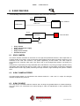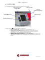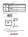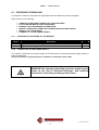
1
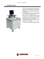
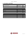
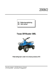
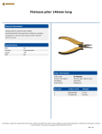
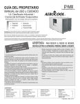
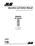
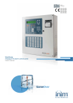
AIX10
A
USER MANUAL
IX 10
X-ray inspection system for PCB multilayers
USER MANUAL
AIX10-MS-1.02-01-UK
PIERGIACOMI ROBOTICS
Via 81ª Strada, 3 (Fraz. Centobuchi)
63030 MONTEPRANDONE (AP)
File: AIX10-MU-003-IT
-1TEL. +39 735 703333 FAX +39 735 703757
http://www.piergiacomi.com e-mail: [email protected]
AIX10
USER MANUAL
TABLE OF CONTENTS
1 INTRODUCTION................................................................................... 4
2 SAFETY REGULATION........................................................................ 5
2.1
2.2
2.3
2.3.1
2.3.2
2.3.3
2.4
2.5
MEANING OF GRAPHIC SYMBOLS LISTED IN THIS MANUAL......................................... 5
GENERAL PRESCRIPTIONS........................................................................................................ 5
SPECIFIC INDICATIONS RELATED TO X-RAY USE ............................................................. 6
LAW REGULATIONS .................................................................................................................... 6
OPERATIONAL PRECAUTIONS RELATED TO THE X-RAY SOURCE .................................. 7
OPERATIONAL PRECAUTIONS RELATED TO THE X-RAY CAMERA................................. 7
MACHINE GROUNDING ............................................................................................................... 7
MEANING OF WARNING SIGNS ON THE MACHINE ............................................................ 8
3 SECURUTY FEATURES IN THE MACHINE CONSTRUCTION ........... 8
3.1
IDENTIFICATION PLATES APPLIED ON THE MACHINE ................................................... 8
4 MACHINE DESCRIPTION .................................................................... 9
5 ELECTRICAL EQUIPMENT.................................................................. 9
6 X-RAY DEVICES ................................................................................ 10
6.1
6.2
6.3
6.4
XRAY CAMERA............................................................................................................................. 10
X-RAY CAMERA FEEDER .......................................................................................................... 10
X-RAY SOURCE ............................................................................................................................ 10
CONTROL PANEL ........................................................................................................................ 11
7 TRANSPORT AND STORING ............................................................ 12
7.1
7.2
MACHINE TRANSPORT.............................................................................................................. 12
STORING CONDITIONS.............................................................................................................. 12
8 INSTALLATION .................................................................................. 13
8.1
8.2
8.3
WORKING AREA .......................................................................................................................... 13
WORKING CONDITIONS............................................................................................................ 13
PREPARING THE MACHINE ..................................................................................................... 14
File: AIX10-MU-003-IT
-2-
AIX10
8.3.1
8.3.2
USER MANUAL
HORIZONTAL POSITIONING OF THE MACHINE .................................................................. 14
CONNECTION TO THE POWER SUPPLY................................................................................. 14
9 MACHINE USE ................................................................................... 15
9.1
9.2
9.3
9.4
9.5
SWITCHING ON AND OFF THE MACHINE............................................................................ 15
X-RAY SOURCE PRE-HEATING ............................................................................................... 15
X-RAY TENSION AND CURRENT ADJUSTMENT ................................................................. 15
INSPECTION.................................................................................................................................. 15
SAFETY AND PROTECTION RULES........................................................................................ 16
10 IMPACT ON THE ENVIRONMENT................................................... 17
11 PREVENTIVE MAINTENANCE......................................................... 18
11.1
11.2
ELECTRIC SYSTEM MAINTANANCE ................................................................................... 18
X-RAY DEVICES MAINTANANCE.......................................................................................... 18
12 MAINTENANCE AND FAILURES SEARCH ..................................... 19
12.1
12.2
12.3
ELECTRICAL FAILURES ......................................................................................................... 19
MECHANICAL FAILURES........................................................................................................ 20
SOFTWARE ERRORS CONDITIONS...................................................................................... 20
13 TECHNICAL FEATURES.................................................................. 21
File: AIX10-MU-003-IT
-3-
AIX10
USER MANUAL
1 INTRODUCTION
This manual was intended to make easy and safe
the use of the AIX10 manufactured by Piergiacomi
Robotics. For safety reasons the reading and
knowledge of this manual by the machine user is
compulsory, therefore if not completely read may
cause damages.
The AIX10 has been designed only and exclusively
for the inspection of PCB and in particular for
dimensional and hole eccentricity analysis
The PC runs on Windows 98 (or higher)
environment, in order to provide a friendly interface.
A keyboard with a trackball is the main machine
interface. This keyboard is located underneath the
working table and it’s easy to slide it out.
The advanced x-ray source, combined with an
optimum vision system give to this x-ray system
very high performance results.
The PC runs on Windows Xp (or higher)
environment, in order to provide a friendly interface.
File: AIX10-MU-003-IT
-4-
AIX10
USER MANUAL
2 SAFETY REGULATION
This manual was intended to make easy and safe the use of the AIX10 manufactured by Piergiacomi
Robotics. For safety reasons the reading and knowledge of this manual by the machine user is
compulsory, therefore if not completely read may cause damages and an increased risk. .
Pay particular attention to those parts concerning x-ray.
Integrating part of this manual are following documents:
• ELECTRICAL EQUIPMENT
• SOFTWARE MANUAL
• X-RAY CAMERA INSTRUCTION MANUAL
• X-RAY SOURCE AND CONTROL INSTRUCTION MANUAL
2.1
MEANING OF GRAPHIC SYMBOLS LISTED IN THIS MANUAL
The exclamation mark, within the equilateral triangle, indicates the
presence of working or maintenance instructions or any situation,
which is, or might become, potentially dangerous. It reminds the kind
of risk involved and the competence required.
The magnifying lens indicates information or details, which might be
useful to the technicians while detecting failures or fixing any
machine’s fault.
Therefore the comprehension of these parts requires an adequate
technical knowledge. This kind of knowledge is not required for the
normal use of the machine.
2.2
GENERAL PRESCRIPTIONS
WARNING !!!
The aim of AIX10 is to check the correct location
and dimension of pads and reference holes on multi-layer PCB. It is also
possible to use the machine for a general PCB inspection. ANY OTHER
USE IS FORBIDDEN
WARNING !!!
The use of this machine is strictly forbidden to
personnel who have not read and deeply understood all AIX10 manuals
WARNING !!!
It is strictly forbidden to tamper with the
security features of this machine. The chassis panels are intended as a
permanent protection and therefore they cannot be removed.
WARNING !!!
In order to install and to start-up the machine, it is extremely important to
respect and to pay attention to safety and prevention regulations.
WARNING !!!
The installation and maintenance have to be
carried out by authorized and appropriately trained personnel only.
File: AIX10-MU-003-IT
-5-
AIX10
USER MANUAL
WARNING !!!
Before any intervention on electrical or
mechanical parts, the power supply disconnection from the machine is
compulsory.
WARNING !!!
In order to minimize any risk of fire or
electrical discharge avoid any contact between any machine’s electrical
part and water or other kind of liquids.
2.3
SPECIFIC INDICATIONS RELATED TO X-RAY USE
The AIX10 uses a device able to generate x-rays.
X-rays are dangerous for the human body
To avoid any kind of problem, Piergiacomi recommends that all following indications are fully respected.
Being x-rays quite complex argument, these indications are divided in 3 groups: law regulations; x-ray
device; image detector (device which transform the x-rays in images).
2.3.1
LAW REGULATIONS
WARNING !!!
The ownership of this machine must be
communicated to the concerned authorities.
WARNING !!!
The use of this machine is subject to a qualified
expert supervision that will check the x-ray emissions with the timing
prescribed by law and will establish operator’s work loads and all the
safety precautions.
WARNING !!!
Check the technical relation supplied with the
machine. In particular pay attention to those parts concerning frequency
evaluations and x-ray protections installed.
WARNING !!!
A doctor will check results of dosimeters.
File: AIX10-MU-003-IT
-6-
AIX10
2.3.2
USER MANUAL
OPERATIONAL PRECAUTIONS RELATED TO THE X-RAY SOURCE
WARNING !!!
Do not tamper, remove, change or leave open
panels or doors. They are fundamental to reduce to the minimum the
quantity of x-ray emissions in the surrounding environment.
WARNING!!!
Do not TAMPER or MODIFY x-ray devices. Do
not EXCLUDE safety locks.
WARNING!!!
Do not install in environment with excessive
dust, humidity, corrosive gas which could cause electrical discharge or
fire.
WARNING!!!
AVOID SHOCKS OR EXCESSIVE VIBRATIONS.
2.3.3
OPERATIONAL PRECAUTIONS RELATED TO THE X-RAY CAMERA
WARNING!!!
AVOID SHOCKS OR EXCESSIVE VIBRATIONS.
2.4
MACHINE GROUNDING
This product has to be grounded. In case of false contacts or loss of insulation, the machine grounding
ensures a low resistance path to avoid any risk of electrical discharge. The machine is provided with a
grounding system which works only if connected to the factory plant’s grounding system by means of a
wire between the machine’s main terminal block and the power supply system (see installation options of
the machine). The supply system has to follow the law prescriptions.
WARNING!!!
An incorrect grounding procedure may cause electrical discharge. Qualified
personnel must check the method used to ground the machine
File: AIX10-MU-003-IT
-7-
AIX10
2.5
USER MANUAL
MEANING OF WARNING SIGNS ON THE MACHINE
The lightning symbol within an equilateral triangle is used to make the
operator aware of “dangerous voltage” presence within the product.
This might be a cause of harm in case of contact
This sign shows the exact location where to position the lifting arms to
perform any machine loading and movement operation
3 SECURUTY FEATURES IN THE MACHINE CONSTRUCTION
The machine has been built following the security regulations in force.
The complete analysis of these aspects is contained within the “Fascicolo Tecnico” (compulsory
document required by the EEC directive 89/392 “enclosure V, Machine Directive”, necessary to have the
conformity certificate to be released). This documentation is available to the authority but not to the
machine buyer.
The producer gives the buyer the conformity certificate, which contains all the regulations the project and
the construction of the machine are based on.
This machine mounts x-ray devices and maximum care has been used on the design and implementation
of shielding structure to reduce to minimum x-ray emissions in the environment.
3.1
IDENTIFICATION PLATES APPLIED ON THE MACHINE
MACHINE PLATE:
This is the machine identification plate, which reports
the main characteristics and the registration number.
It is located on the machine’s structure.
AIX 10
224 kg
4A
X-RAY TUBE
Model:
S/N:
IS601.5
----------
X-RAY PLATE:
This is the x-ray device plate. It is located inside the
machine.
--------
High Voltage range min.:
22kV
High Voltage range max.:
65 kV
Current range min.:
0,12 mA
Current range max.:
1,5 mA
File: AIX10-MU-003-IT
-8-
AIX10
USER MANUAL
4 MACHINE DESCRIPTION
The AIX10 manufactured by Piergiacomi ROBOTICS is only and exclusively an x-ray inspection system
for multi-layer PCBs.
X-RAY SOURCE OVER
HEATING LIGHT
MONITOR LCD
KEYBOARD
X-RAY ON LIGHT
X-RAY SOURCE
CONTROLS
Tension kV
Current mA
SWITCH ON KEY
PCB INSERTION AREA
PC ACCESS DOOR
Fig.4.1
5 ELECTRICAL EQUIPMENT
For what concerns electrical system connections and schemas, see “Electrical Equipment” document.
The electrical equipment, apart from electro mechanic components, includes also electronic sub systems:
• X-ray devices
• Control system
When any action on the machine is needed please pay attention to the following warnings:
WARNING !!!
Installation and maintenance operations must
be performed by authorized trained personnel only.
WARNING !!!
Before any operation on electrical and/or
mechanical parts, it is mandatory to disconnect the machine from the
electrical power supply.
File: AIX10-MU-003-IT
-9-
AIX10
USER MANUAL
6 X-RAY DEVICES
In the following scheme all x-ray devices and their main connections are shown:
230 Vac
XRAY CAMERA
POWER SUPPLY
12 V
CAMERA
XRAY CAMERA
VIDEO OUT
COMPUTER
230 Vac
X-RAY SOURCE
CONTROL
X RAY SOURCE
kV and mA
control
Fig. 6
•
•
•
•
•
6.1
X-Ray Camera
X-Ray camera power supply
X-Ray source
X-Ray source control
kV and mA control
XRAY CAMERA
The X-RAY Camera mounted on the AIX10 it is an high level performance device, which apart from an
excellent quality of its images, it has an extremely high sensitivity which allows a minimum amount of x-ray
emissions to be used. The camera is 12V power supplied by its own feeder. The video output is
connected at the computer video input. This device has to be managed with extreme care being very
fragile.
Cameras are composed by an image intensifier which translate the x-ray energy into light quantum and by
optic fibers which transmit the light to a CCD. Then, an electronic circuit system, produce an analogical
standard video format. High quality cameras gives high resolution, high sensitivity and optimum contrast
level..
6.2
X-RAY CAMERA FEEDER
The power supply feeder, it is connected to the network at 230V a.c. with a 12V c.c. output. The red light
indicates output tension presence.
6.3
X-RAY SOURCE
The x-ray source is located inside the machine and it is easily recognizable thanks to a label indicating it.
The x-ray source it is connected to its control through a cable. No adjustments or other operations are
needed.
File: AIX10-MU-003-IT
- 10 -
AIX10
6.4
USER MANUAL
CONTROL PANEL
The control panel manages the c-ray sources and X,Y,Z axes movement:
X-RAY SOURCE OVER
HEATING LIGHT
X-RAY ON LIGHT
“BY EYES”
INSPECTION WINDOW
CURRENT CONTROL
mA
SWITCH ON KEY
TENSION CONTROL kV
Fig. 6.4A
For what concerns x-ray, main elements to be considered are:
•
•
•
•
X-RAY ON AND OFF KEY Turning this key x-ray are switched on or off.
X-RAY SOURCE OVER HEATING LIGHT this light turns on when there is an over
heating of the x-ray source. Therefore it should be always turned off. In case of over
heating switch off x-ray and switch them on after few minutes.
X-RAY ON LIGHT this light is turned on when x-ray are switched on
CURRENT AND TENSION CONTROLS using the appropriate knobs, located on the
control panel, it is possible to adjust current from 0,12 to 1,5 mA and x-ray tension from 0
to 65 kV
File: AIX10-MU-003-IT
- 11 -
USER MANUAL
AIX10
7 TRANSPORT AND STORING
WARNING !!!
All transport operations require a great care and
should be performed by trained personnel only.
WARNING !!!
THE XRAY CAMERA CANNOT BE EXPONED TO SCHOCK OR EXCESSIVE
VIBRATIONS THEREFORE IT IS NECESSARY TO DEEPLY EVALUATE THE
NEED TO REMOVE IT FROM ITS LOCATION.
7.1
MACHINE TRANSPORT
In order to safely perform all transport operations, the machine is set on a pallet whose dimension,
together with the center position, is reported in the scheme below.
The following plate indicates the lifting points:
In this drawing the machine center position is reported:
1 mt
Center position
1 mt
Lifting points
weight 250 kg
height 1.67 mt
Fig. 8.1
7.2
STORING CONDITIONS
If a certain amount of time will pass between the transportation and the installation of the XDM30, the
machine has to be stored following the following conditions and leaving it in the original packaging:
• Temperature while not working 0°C ÷ +50°C
• Humidity lower than 80% and without condensation
File: AIX10-MU-003-IT
- 12 -
USER MANUAL
AIX10
8 INSTALLATION
WARNING !!!
The installation of the AIX10 requires a deep
knowledge of the machine and therefore it has to be carried out by
specifically trained personnel only.
8.1
WORKING AREA
The Picture below shows the minimum area dimensions required to correctly work with the AIX10 and to
keep it in good functioning conditions.
170cm
96cm
165cm
90cm
160cm
Fig. 8.1
8.2
WORKING CONDITIONS
The section below list working conditions needed in terms of factory’s installations and environment.
ENVIROMENT CONDITIONS
•
•
•
Temperature while working
Temperature while not working
Humidity
:
:
:
+15 °C ÷ + 35 °C
0 °C ÷ + 50°C
lower than 70% and without condensation
Do not install the machine in dusty environment.
File: AIX10-MU-003-IT
- 13 -
AIX10
8.3
USER MANUAL
PREPARING THE MACHINE
To prepare the machine, first prepare an appropriate area as indicated in previous paragraph.
Step sequence is the following:
REMOVE THE MACHINE FROM PALLET AND PACKAGING
PLACE THE MACHINE IN THE CHOSEN AREA
BE SURE THAT THE MACHINE IS HORIZONTAL
MOUNT THE SUPPORT HARM FOR THE MONITOR AND PLACE CABLES
INSTALL THE LCD MONITOR
CONNECTI IT TO THE POWER SUPPLY
•
•
•
•
•
•
8.3.1
HORIZONTAL POSITIONING OF THE MACHINE
8.3.1.1.1
Steps
1
2
8.3.2
HORIZONTAL POSITIONING OF THE MACHINE
Description
Adjust the four anti vibrating feet
Tighten the locking nuts on the feet.
CONNECTION TO THE POWER SUPPLY
The machine connection to the power supply can be done simply connecting the power supply cable to a
230V grounded plug.
Set the connection using all protections needed for a maximum load of 1 kW.
WARNING!! An improper grounding procedure might expose
people to the risk of electrical discharge. Ask qualified
personnel to check the grounding method used.
File: AIX10-MU-003-IT
- 14 -
AIX10
USER MANUAL
9 MACHINE USE
Here below all main operative steps are listed:
•
•
•
•
SWITCH ON (AND OFF) THE MACHINE
SET UP X-RAY DEVICES
X-RAY SOURCE PRE-HEATING
INSPECTION
When the upper red light is on, it means that the x-ray is on
9.1
SWITCHING ON AND OFF THE MACHINE
To switch on the machine, press the [ON] button located in the machine’s back. The red light on means
that the machine is connected and the power supply is working. Afterwards turn on the start key in the
front panel.
Before switching off the machine execute the function <END> from the application program (see Software
manual) and wait for the computer to turn off. Afterwards turn anticlockwise the start key.
WARNING !!! To avoid functioning errors switch off the
machine only after stopping the job selecting the software
option <END> from the main menu.
9.2
X-RAY SOURCE PRE-HEATING
After the machine and the x-ray source are switched on, this last one needs 1 or 2 seconds of pre-heating.
The operation comes in automatic.
9.3
X-RAY TENSION AND CURRENT ADJUSTMENT
To perform an optimal inspection it is necessary to adjust the x-ray source current µA and tension kV.
The needed values depend on the kind of circuit and on the distance between x-ray source and x-ray
camera. To adjust these parameters, turn the apposite knobs on the main control mask located on the
machine’s front side.
9.4
INSPECTION
After all adjustments have been made, it is possible to start the inspection.
1
2
INSPECTION PROCEDURE
Be sure that x-ray source is switched off
Insert the circuit that has to be inspected under the camera (inserting it
inside the proper window)
3
4
5
Switch on the x-ray source using the starting key
Set the camera in “Live” status using the appropriate button
Adjust the x-ray source current µA and tension kV.
6
Move manually the circuit to search for areas to be inspected and
measured
File: AIX10-MU-003-IT
- 15 -
AIX10
7
8
9
USER MANUAL
Adjust brightness and contrast levels
Execute measuring steps
Check results on monitor
Other operative steps
The AIX10 gives also the following options:
• Save and recall images previously saved
• Use filters to improve image vision.
9.5
SAFETY AND PROTECTION RULES
Main safety and protection rules concerning the machine’s use (extracted from the technical
report on the PHYSICAL SURVEILLANCE ON IONIZING RADIATION PROTECTION), are listed
below:
1
The x-ray inspection is allowed in the case it is not possible to use alternative way of inspection
able to give same information on the circuit status
2
The use of the system is allowed only to authorized personnel.
3
Before switching on the x-ray be sure of the correct set up of radiation data
4
Limit operations to a strictly needed number.
5
Pregnant women operating on the system must communicate their condition as soon as they
know it.
6
Any situation which involves a serious and immediate danger must communicated immediately to
the Responsible Qualified Expert.
7
Once the inspection is ended, the x-ray emission must be stopped.
File: AIX10-MU-003-IT
- 16 -
AIX10
USER MANUAL
10 IMPACT ON THE ENVIRONMENT
The AIX 10 has a minimum impact on the environment. Main information is listed below:
• Dust pollution:
none.
• Oil pollution:
none.
• Acoustic pollution:
none.
• Heating pollution:
This machine doesn’t use heating sources.
The average consumption is less than 1 KW.
• X-ray emissions:
Aix 10 uses x-ray.
The best equipment and devices have been used to reduce to minimum x-ray emissions
to the environment. Furthermore, an extremely efficient shielding system have been
designed, realized and mounted to assure maximum safety for operators
File: AIX10-MU-003-IT
- 17 -
AIX10
USER MANUAL
11 PREVENTIVE MAINTENANCE
WARNING!!
All maintenance operations have to be performed
while the machine is shut down and not connected to the power supply.
WARNING!!
All maintenance operations have to be performed
by specifically trained and authorized personnel only
In order to keep the machine in a good state it is advisable to follow a preventive maintenance program.
11.1 ELECTRIC SYSTEM MAINTANANCE
ACTION
Check the grounding connections.
Check the fuses status on the electrical panel
FREQUENCY
Monthly
Monthly
11.2 X-RAY DEVICES MAINTANANCE
Both cameras and x-ray sources do not need maintenance.
File: AIX10-MU-003-IT
- 18 -
AIX10
USER MANUAL
12 MAINTENANCE AND FAILURES SEARCH
WARNING!!
The fault searching procedure requires a machine
deep knowledge, therefore has to be carried out by specifically trained
personnel only.
WARNING!!!
If any problem persists call the Technical
Assistance Service.
In case of faulty situation on the machine, in order to restore the normal working conditions as soon as
possible, it is important to hold on the following prescriptions avoiding any further or possible damage.
If no evident mechanical damages can be seen it is possible to start with the fault searching.
Failures may belong to one of the following three categories:
• ELECTRICAL
• MECHANICAL
• SOFTWARE ERRORS
WARNING!!! Any operation on the machine for which it
is necessary to act in the inside of the machine, needs to
remove external panels. Before doing so it is mandatory to
disconnect the machine from the power supply. Furthermore,
if x-ray is on while the panels are not at their place
(removed), this would expose the operator to emissions
dangerous for their health.
When maintenance operation is finished mount back exactly
in the same way has been founded any panel previously
removed using all screws available
12.1 ELECTRICAL FAILURES
1
None of the system lights is on.
Check that the general interrupter is on
Check that the power supply cable is connected.
Check that the power supply corresponds to 230V AC 50Hz.
Check fuses in the electric panel.
2
The computer doesn’t start
Check that the power supply cables are properly connected
Check that the video signal wire is properly connected.
For any other kind of errors refer to the PC’s user manual.
3
There is no image on the monitor
If there is no image on the monitor, it could be due to software problems, x-ray camera
problems or x-ray emissions absence.
If there is a problem with the camera, a red cross should be displayed on the part of the
video dedicated to images.
Check that the system is in Live mode
Check that the camera is 12V power supplied.
File: AIX10-MU-003-IT
- 19 -
AIX10
USER MANUAL
Check the cable connected to the frame grabber
Check fuses on the x-ray power supply
12.2 MECHANICAL FAILURES
1
Mechanical failures are easily detected
If there are evident breaks, broken parts should be replaced
If there is components misalignment or misplacement the original situation should be
restored.
These misalignment are evident if one axis movement tends to block when it is close to
extremities
12.3 SOFTWARE ERRORS CONDITIONS
Di seguito vengono riportati gli errori gestiti dal software con le possibili cause e rimedi.
N. ERR.
PROBLEM
Image not loadable !
125
126
Impossible to save file of image !
CHECK
Check that the image file exists and that the memory
support is not damaged.
Check that the memory support is not damaged or full.
WARNING !!! If problems continue, please call
Piergiacomi Technical Service
File: AIX10-MU-003-IT
- 20 -
AIX10
USER MANUAL
13 TECHNICAL FEATURES
Maximum panel dimensions
Circuit thickness
LCD Monitor
Front window in shielding material
X-ray tube tension
X-ray tube current
View area
CCD camera
Resolution
Safety
MACHINE TECHNICAL FEATURES
There are no limits to the mm
movement along the x
axis. Y AXIS 800
From 1 to 8
mm
17
“
X-RAY DEVICES FEATURES
100 x 120
60
1.3
1.3
Ø 25mm or 8.4x6.3 mm
9,6 pair of lines/mm.
<1
mm.
kV.
mA.
“
uSvh
GENERAL FEATURES
Dimensions
Functioning temperature
Not functioning temperature
Humidity
Power supply
Power consumption
Marchio
96 x 90 x 154
+15°C ÷ +35°C
0°C ÷ +50°C
< 70% e senza condensa
230V ac 50Hz
1kW
CE
cm.
File: AIX10-MU-003-IT
- 21 -
AIX10
USER MANUAL
IMPORTANT NOTICE
Piergiacomi Robotics would like to thank in advance all users that will point
out defects or send us advises in order to help us to improve working and
safety features of the AIX10.
File: AIX10-MU-003-IT
- 22 -