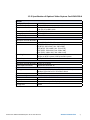
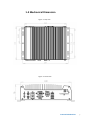
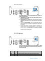
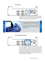
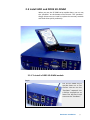
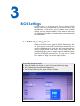
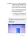
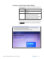
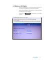
1
EC-3000 USER
Intel® Core™ i7/i5 Fanless Embedded Controller
Manual
1st Edition 04/27/2011
All information is subject to change without notice.
Worldwide Technical Support and Product Information
www.vecow.com
Vecow Corporate Headquarters
4F No52 Aly3 Lane182 Section 2 WenHua Rd Panchiao Dist New Taipei City Taiwan
Tel: 886 2 2258 5665
For further support information, refer to the Technical Support and Professional Services
appendix. To comment on Vecow Co., Ltd. documentation, refer to the Vecow Co., Ltd. web
site at www.vecow.com.
© 2009–2011 Vecow Co., Ltd. All rights reserved.
Record of Revision
Version
V1.00
V1.01
Date
May 23 2011
Oct. 27 2011
Page
All
40-41
Description
Perliminary Release
Appendix I
Remark
Declaimer
This manual is intended to be used as a practical and informative guide only and
is subject to change without prior notice. It does not represent commitment from
Vecow Co., Ltd. Vecow shall not be liable for direct, indirect, special, incidental, or
consequential damages arising out of the use of the product or documentation,
nor for any infringements upon the rights of third parties, which may result from
such use.
Declaration of Conformity
FCC This equipment has been tested and found to comply with the limits for a Class
A digital device, pursuant to part 15 of the FCC Rules. These limits are designed
to provide reasonable protection against harmful interference when the
equipment is operated in a commercial environment. This equipment generates,
uses, and can radiate radio frequency energy and, if not installed and used in
accordance with the instruction manual, may cause harmful interference to radio
communications. Operation of this equipment in a residential area is likely to
cause harmful interference in which case the user will be required to correct the
interference at his own expense.
CE
The product(s) described in this manual complies with all applicable European
Union (CE) directives if it has a CE marking. For computer systems to remain CE
compliant, only CE-compliant parts may be used. Maintaining CE compliance also
requires proper cable and cabling techniques.
Copyright and Trademarks
This document contains proprietary information protected by copyright. All rights
are reserved. No part of this document may be reproduced by any mechanical,
electronic, or other means in any form without prior written permission of
the manufacturer. Company/product names mentioned herein are used for
identification
©Vecow EC-3000 Embedded System Series User Manual
iv
Packing List
Item
Description
Qty
1 EC-3000 Series fanless controller
1
(According to the configuration you order, the EC-3000 series may contain HDD and
DDR3 SO-DIMM. Please verify these items if necessary.)
2 Accessory box, which contains
● Vecow Drivers & Utilities DVD
1
● Wall-mounting bracket
2
● M4 screws for wall-mounting bracket
4
● Foot pad
4
● 4-pin pluggable terminal block
1
1
● HDD thermal pad
3 Quick Installation Guide
1
Order Information
Part Number
EC-3000-3G
EC-3000-5G
Description
Intel® Core™ i7/i5 Fanless Embedded Controller with 3x GbE, 2x eSATA, 4x COM
Intel® Core™ i7/i5 Fanless Embedded Controller with 5x GbE, 2x eSATA, 4x COM
Optional Accessories
Part Number
VMX-200-4
VMX-200-8
PWA-60W
Description
4-CH, D1, Real-time, Mini-PCI Express, 120 fps, Video Capture Card, include
cables and SDK
8-CH, D1, Real-time, Mini-PCI Express, 240 fps, Video Capture Card, include
cables and SDK
60W AC/DC power adapter
v
Table of Contents
Declaimer
Declaration of Conformity
Copyright and Trademarks
iv
iv
iv
FCC
CE
iv
iv
General Introduction
1
Packing List
Order Information
Optional Accessories
v
v
v
1.1 Overview
1.2 Product Specification
1
2
1.3 Supported CPU List
1.4 Mechanical Dimension
6
7
Hardware Installation
9
1.2.1 Specification of Vecow EC-3000-3G
1.2.2 Specification of Vecow EC-3000-5G
1.2.3 Specification of Optional Video Capture Card-VMX-200-4
1.2.4 Specification of Optional Video Capture Card-VMX-200-8
2
3
4
5
2.1 Front Side External I/O Connectors
9
2.2 Rear Side External I/O Connectors
14
2.3 Install HDD and DDR3 SO-DIMM
17
2.4 Wall-Mount EC-3000 series 2.5 Power Supply 21
23
2.6 Power Management 25
2.1.1 Audio Jacks
2.1.2 PS/2 Keyboard and Mouse Connectors
2.1.3 USB Connectors
2.1.4 Gigabit Ethernet Port
2.1.5 DVI/HDMI Connector
2.1.6 VGA Connector
2.1.7 eSATA Ports
2.1.8 CF Socket
2.1.9 Power Button
2.1.10 LED Indicators
2.2.1 DC Input Terminal Block
2.2.2 DC Jack
2.2.3 Gigabit Ethernet Ports
2.2.4 COM Ports 2.3.1 To install a DDR3 SO-DIMM module
2.3.2 To install a HDD
2.5.1 To connect DC power via the 4-pin pluggable terminal block 2.6.1 Using the power button on the front panel 2.6.2 Using remote on/off control on the rear panel 2.6.3 Using Wake-on-LAN function 9
9
10
10
11
11
12
12
13
13
14
15
15
16
17
18
23
25
25
27
vi
BIOS Settings
31
3.1 COM1 Operating Mode 3.2 SATA Controller Mode 3.3 CPU Shutdown Temperature & Thermal Throttling 3.4 Power-on after Power Failure Option 3.5 Wake-on-LAN Option 3.6 Select a Boot Device 3.7 Operating System Support 31
32
33
34
35
36
37
Software Installation 38
4.1 Windows XP 4.2 Windows 7 or Windows Vista 32-bit 4.3 Windows 7 or Windows Vista 64-bit 38
39
39
Appendix I 40
AT/ATX Power Mode Select AT Mode Behavior ATX Mode Behavior 40
40
41
vii
1
General Introduction
1.1 Overview
Incorporating Intel® Core™ i7/i5 processor, Vecow EC-3000
controller offers extraordinary performance for arithmeticintensive applications, while its fanless design provides
superb reliability and durability.
Especially design for harsh environment, the Vecow EC-3000
can process various advanced measurement and control
applications ranging in ambient temperatures between -20
and 60 degrees Celsius.
The fanless design of EC-3000 gives it exceptional longterm durability and tolerance to vibration because all heatproducing components are placed close with the aluminum
housing.
The all-in-one embedded box PC features rich I/O interfaces,
including maximum 5 Gigabit Ethernet ports and 2 eSATA
ports particularly for surveillance and security applications.
The VGA+DVI/HDMI dual display accomplishes an easy
way of high-resolution content output for image or media
applications. In addition, EC-3000 also provides mini-PCIe, to
fit a broader range of applications.
General Introduction
1
1.2 Product Specification
1.2.1 Specification of Vecow EC-3000-3G
System
Processor
Chipset
Memory
BAck Panel I/O
LAN 1, 2, 3, 4, 5
Display
Serial Port
USB
KB/MS
Audio
eSATA
CompactFlash
Internal I/O
SATA
Mini PCI-E
PCI-104
Power Input
DC-In
Mechanical
Size ( W x D x H)
Weight
Mounting
Environmental
Operating Temperature
Storage Temperature
Humidity
Vibration
Shock
EMC
Intel® Core™ i7/i5 Mobile Processors:
i7-620M (2.66 GHz) ,
i5-520M (2.4 GHz),
P4500 (1.86 GHz)
Intel® HM55
1x SO-DIMM socket,
support up to 4GB DDR3 1066MHz SDRAM
Gigabit Ethernet controller
VGA, up to 2560 x 1600 resolution
DVI-D, up to 1920 x 1080 resolution
COM1: RS-232/422/485 (Programmable by software)
COM2, COM3, COM4: RS-232
6x USB 2.0 ports
1x PS/2 keyboard and 1x PS/2 mouse
1x Mic-in and 1x speaker-out
2x eSATA ports
1x Type-I CF socket
1x SATA Port with power pins for 2.5" HDD/SSD installation
1x Mini-PCIe socket
1x internal PCI-104 socket (Optional with reserved footprint)
DC input by two selections:
Selection 1: 8-26 Volts 4-pin pluggable terminal block with
remote on/off control
Selection 2: 12 Volts DC jack (Ø2.5) for AC/DC adapter input
240mm x 195mm x 76mm
2.7 Kg
Wall-mount by mounting bracket
-20°C to 70°C
-40°C to 85°C
10% to 90% humidity, non-condensing
Operating, 5 Grms, 5-500 Hz, 3 Axes
(w/SSD, according to IEC60068-2-64)
Operating, 50 Grms, Half-sine 11 ms duration
(w/SSD, according to IEC60068-2-27)
CE/FCC Class A
©Vecow EC-3000 Embedded System Series User Manual
General Introduction
2
1.2.2 Specification of Vecow EC-3000-5G
System
Processor
Chipset
Memory
Back Panel I/O
LAN 1, 2, 3, 4, 5
Display
Serial Port
USB
KB/MS
Audio
eSATA
CompactFlash
Internal I/O
SATA
Mini PCI-E
PCI-104
Power Input
DC-In
Mechanical
Size ( W x D x H)
Weight
Mounting
Environmental
Operating Temperature
Storage Temperature
Humidity
Vibration
Shock
EMC
Intel® Core™ i7/i5 Mobile Processors:
i7-620M (2.66 GHz) ,
i5-520M (2.4 GHz),
P4500 (1.86 GHz)
Intel® HM55
1x SO-DIMM socket,
support up to 4GB DDR3 1066MHz SDRAM
Gigabit Ethernet controller
VGA, up to 2560 x 1600 resolution
DVI-D, up to 1920 x 1080 resolution
COM1: RS-232/422/485 (Programmable by software)
COM2, COM3, COM4: RS-232
6x USB 2.0 ports
1x PS/2 keyboard and 1x PS/2 mouse
1x Mic-in and 1x speaker-out
2x eSATA ports
1x Type-I CF socket
1x SATA Port with power pins for 2.5" HDD/SSD installation
1x Mini-PCIe socket
1x internal PCI-104 socket (Optional with reserved footprint)
DC input by two selections:
Selection 1: 8-26 Volts 4-pin pluggable terminal block with
remote on/off control
Selection 2: 12 Volts DC jack (Ø2.5) for AC/DC adapter input
240mm x 195mm x 76mm
2.7 Kg
Wall-mount by mounting bracket
-20°C to 70°C
-40°C to 85°C
10% to 90% humidity, non-condensing
Operating, 5 Grms, 5-500 Hz, 3 Axes
(w/SSD, according to IEC60068-2-64)
Operating, 50 Grms, Half-sine 11 ms duration
(w/SSD, according to IEC60068-2-27)
CE/FCC Class A
General Introduction
3
1.2.3 Specification of Optional Video Capture Card-VMX-200-4
General
Bus Type / Form Factor
Dimensions (L x H)
I/O connector
Mini PCI Express
51mm x 30mm
1x 16 pin headers to D-Sub 15 cables
1x D-Sub 15 to BNC cable
FCC, CE, RoHS Compliance
-40°C to 85°C
0°C to 60°C
Environment Certification
Storage Temperature
Operate Temperature
Video
Maximum Channel Number 4
Input Connector
4 input BNC to D-Sub 15
Resolution
D1 (NTSC: 720 x 480 / PAL: 720 x 576)
CIF (NTSC: 360 x 240 / PAL: 360 x 288)
4CIF (NTSC: 704 x 480 / PAL: 704 x 576)
DCIF (NTSC: 528 x 320 / PAL: 528 x 384)
QCIF (NTSC: 180 x 120 / PAL: 180 x 144)
Recording Rate
4CH with full D1 resolution
120 fps on NTSC system, 100 fps on PAL system
Video Compression Format H.264 / MJPEG
Audio
Maximum Channel Number 4 mono or 2 stereo
Audio Input Connector
4 input RCA to D-Sub 15
Software
OS Support
WindowsXP/VISTA/Windows7 (32 Bits or 64 Bits)
Standard Linux kernel 2.6.32 and all above
SDK
VC++ / .NET
Recommend System
CPU
Intel Core 2 Duo E4500 2.2GHz
Memory
1GB
Graphics Unit
DirectX 9.0c compatible display card
Storage Size
500GB
©Vecow EC-3000 Embedded System Series User Manual
General Introduction
4
1.2.4 Specification of Optional Video Capture Card-VMX-200-8
General
Bus Type / Form Factor
Dimensions (L x H)
I/O connector
Mini PCI Express
51mm x 30mm
2x 16 pin headers to D-Sub 15 cables
2x D-Sub 15 to BNC cable
FCC, CE, RoHS Compliance
-40°C to 85°C
0°C to 60°C
Environment Certification
Storage Temperature
Operate Temperature
Video
Maximum Channel Number 8
Input Connector
2x 4 input BNC to D-Sub 15
Resolution
D1 (NTSC: 720 x 480 / PAL: 720 x 576)
CIF (NTSC: 360 x 240 / PAL: 360 x 288)
4CIF (NTSC: 704 x 480 / PAL: 704 x 576)
DCIF (NTSC: 528 x 320 / PAL: 528 x 384)
QCIF (NTSC: 180 x 120 / PAL: 180 x 144)
Recording Rate
8CH with full D1 resolution
240 fps on NTSC system, 100 fps on PAL system
Video Compression Format H.264 / MJPEG
Audio
Maximum Channel Number 8 mono or 2 stereo
Audio Input Connector
2x 4 input RCA to D-Sub 15
Software
OS Support
WindowsXP/VISTA/Windows7 (32 Bits or 64 Bits)
Standard Linux kernel 2.6.32 and all above
SDK
VC++ / .NET
Recommend System
CPU
Intel Core 2 Quad Q8400 2.66GHz
Memory
1GB
Graphics Unit
DirectX 9.0c compatible display card
Storage Size
750GB
General Introduction
5
1.3 Supported CPU List
Vecow EC-3000 accepts a PGA-type Intel® i7/i5 processors
via a rPGA988 CPU socket. The following processors have
been tested by Vecow Co., Ltd. for the compatibility with
Vecow EC-3000. Instead of i7-620M, i5-520M and Celeron
P4500, You may also select other processor according to
your consideration of cost and performance.
i7-640M 2.8 GHz
i5-580M 2.66 GHz
i5-560M 2.66 GHz
i5-540M 2.53 GHz
i5-520M 2.4 GHz *
i3-380M 2.53 GHz
i3-370M 2.40 GHz
Celeron P4500 1.86 GHz *
Pentium P6000 1.86 GHz
i7-620M 2.66 GHz *
i5-480M 2.66 GHz
i5-460M 2.53 GHz
i5-450M 2.4 GHz
i5-430M 2.26 GHz
i3-350M 2.26 GHz
i3-330M 2.13 GHz
The processors with * are listed in Intel® Embedded Roadmap
and with a 7-year life cycle support (from 2010 to 2016).
©Vecow EC-3000 Embedded System Series User Manual
General Introduction
6
1.4 Mechanical Dimension
Figure 1.1 Top view
Figure 1.2 Front view
General Introduction
7
Figure 1.3 Side view
Figure 1.4 Bottom view
©Vecow EC-3000 Embedded System Series User Manual
General Introduction
8
2
Hardware Installation
2.1 Front Side External I/O Connectors
On EC-3000 series, all I/O connectors are located on front
panel and rear panel. Most general computer connectors (i.e.
audio, USB, keyboard/mouse, VGA and etc.) are placed on
the front panel.
2.1.1 Audio Jacks
On EC-3000 series, all I/O connectors are located on front
panel and rear panel. Most general computer connectors
(i.e. audio, USB, keyboard/mouse, VGA and etc.) are placed
on the front panel. To utilize the audio function in Windows,
you need to install corresponding drivers for both Intel®
HM55 PCH chipset and Realtek ALC262 codec. Please refer to
section 4 for information of driver installation.
2.1.2 PS/2 Keyboard and Mouse Connectors
Support of legacy PS/2 keyboard and mouse on EC-3000
series is implemented using industrial-grade ITE8783
Super IO chip (-40 to 85°C). There are two 6-pin MiniDIN connectors on the panel. The purple one is for PS/2
keyboard, and the green one is for PS/2 mouse.
Hardware Installation
9
2.1.3 USB Connectors
There are totally 6 USB ports on the front panel. By BIOS
default, these USB ports are operated in EHCI (Enhanced
Host Control Interface) mode and are compatible to USB 2.0,
USB 1.1 and USB 1.0 devices. Legacy USB support is provided
so you can use USB keyboard/mouse in DOS environment.
2.1.4 Gigabit Ethernet Port
EC-3000 series controller offers 5 GbE ports (EC-3000-5G)
or 3 GbE ports (EC-3000-3G) using Intel® 82574L Gigabit
Ethernet controllers. Each port has one dedicated GbE
controller and one dedicated PCI Express link to present
maximal network performance. One of these GbE ports is
located on the front panel. When plugging in the Ethernet
cable, you can tell the Ethernet status and speed from the
LED indicators on the RJ45 connector as following:
Active/Link LED
LED Color Status
Off
Yellow On
Flashing
Description
Ethernet port is disconnected
Ethernet port is connected and no data transmission
Ethernet port is connected and data is transmitting/receiving
Speed LED
LED Color Status
Off
Green /
Green
Orange
Orange
Description
10 Mbps
100 Mbps
1000 Mbps
©Vecow EC-3000 Embedded System Series User Manual
Hardware Installation
10
2.1.5 DVI/HDMI Connector
The DVI-D connector on the front panel supports both DVI
and HDMI operation mode. This connector can either output
DVI signals or HDMI signal. The DVI output mode supports up
to 1600x1200 resolution and HDMI output mode supports
up to 1920x1080 resolution. The DVI or HDMI mode is
automatically selected according to the display device
connected. You shall need a DVI-D to HDMI cable when
connecting to a HDMI display device.
To utilize the VGA or DVI/HDMI output in Windows, you
need to install corresponding graphics driver. Please refer to
section 4 for information of driver installation.
2.1.6 VGA Connector
VGA connector is the most popular way to connect a display.
The VGA output of EC-3000 series supports up to 2560 x
1600 resolution. By BIOS default, both VGA and DVI/HDMI
output are enabled. To utilize the VGA or DVI/HDMI output
in Windows, you need to install corresponding graphics
driver. Please refer to section 4 for information of driver
installation.
Hardware Installation
11
2.1.7 eSATA Ports
eSATA is a convenient way to extend storage devices. Devices
with SATA interface, such as hard drive and CD/DVD drive,
can be attached to the EC-3000 series controller via eSATA
ports. In addition, eSATA interface supports hot-plug if SATA
controller is configured as AHCI (Advanced Host Controller
Interface) mode. Please refer to section 3.2 for setting SATA
controller mode in BIOS.
2.1.8 CF Socket
EC-3000 series provides a CF socket on the front panel for
Type I CompactFlash card. It is implemented by a SATA-toIDE bridge chip. For best compatibility, configuring SATA
controller as IDE mode is highly recommended if you want
to use CF card in your system. Please refer to section 3.2 for
setting SATA controller mode in BIOS.
©Vecow EC-3000 Embedded System Series User Manual
Hardware Installation
12
2.1.9 Power Button
The power button is a non-latched switch with LED for ATX
mode on/off operation.
• To turn on the EC-3000, press the power button and the
blue LED is lighted up.
• To turn off the EC-3000 series, you can either issue a
shutdown command in OS, or just simply press the power
button.
• In case of system halts, you can press and hold the
power button for 5 seconds to compulsorily shut down
the system.
• Please note that a 5 seconds interval is kept by the
system between two on/off operations (i.e. once turning
off the system, you shall wait for 5 seconds to initiate
another power-on operation).
2.1.10 LED Indicators
There are three LED indicators on the front panel: CF, HDD
and WDT. The descriptions of these three LED are listed in
the following table.
Indicator
CF
HDD
WDT
Color
Green
Red
Yellow
Description
CF indictor, flashing when CompactFlash card is active.
Hard drive indicator, flashing when SATA hard drive is active.
Watchdog timer indicator, flashing when watchdog timer is started.
Hardware Installation
13
2.2 Rear Side External I/O Connectors
Power input, GbE ports, COM ports and optional isolated DIO
are located on the rear panel. In this section, we’ll illustrate
connectors on the rear panel.
2.2.1 DC Input Terminal Block
EC-3000 series allows a wide range of DC power input from 8
to 26V. It provides two ways for connecting DC power: a 4-pin
pluggable terminal block or a DC jack. The 4-pin pluggable
terminal block is fit for field usage where DC power is usually
provided. And the screw clamping connection of terminal
block gives a very reliable way of wiring the DC power. In
addition to 2 pins for DC power input (V+, V-), the terminal
block offers another 2 pins for remote on/off control (Ctrl+,
Ctrl-). You can wire these two pins to an external switch
to control system on/off in AT mode. The following table
describes the pin definition of the pluggable terminal block.
For detail information of connecting DC power and remote
on/off control, please refer to section 2.6.
Pin
V+
VCtrl+
Ctrl-
Description
Positive polarity of DC power input.
Negative polarity of DC power input (usually power ground).
Control pin to connect a latched on/off switch (polarity is negligible).
Control pin to connect a latched on/off switch (polarity is negligible).
Hardware Installation
CAUTION!
CAUTION!
©Vecow EC-3000 Embedded System Series User Manual
1. Please make sure the voltage of DC power
is correct before you connect it to EC-3000
series. Supplying a voltage over 26V will
damage the system.
2. You should use either 4-pin pluggable
terminal block or DC jack for DC power input.
DO NOT supply power to both connectors at
the same time.
14
2.2.2 DC Jack
The DC jack on the rear panel provides another way for
supplying DC power. It’s convenient for indoor usage where
AC power is usually available. The DC jack is designed to use
with a 12V AC/DC adapter with a ø2.5/5.5 plug.
CAUTION!
CAUTION!
1. The rated voltage of DC jack is 16V. Supplying
a voltage over 16V may cause safety issue.
2. You should use either 4-pin pluggable
terminal block or DC jack for DC power input.
DO NOT supply power to both connectors at
the same time.
2.2.3 Gigabit Ethernet Ports
There are another 4 GbE ports (EC-3000-5G) or 2 GbE
ports (EC-3000-3G) on the rear panel. There GbE ports
are implemented using Intel® 82574L Gigabit Ethernet
controllers. Each port has one dedicated GbE controller and
one dedicated PCI Express link to present maximal network
performance. When plugging in the Ethernet cable, you can
tell the Ethernet status and speed from the LED indicators on
the RJ45 connector as following:
Hardware Installation
15
Active/Link LED
LED Color Status
Off
Yellow On
Flashing
Description
Ethernet port is disconnected
Ethernet port is connected and no data transmission
Ethernet port is connected and data is transmitting/receiving
Speed LED
LED Color Status
Off
Green /
Green
Orange
Orange
Description
10 Mbps
100 Mbps
1000 Mbps
To utilize the GbE port in Windows, you need to install corresponding driver for Intel®
82574L GbE controller. Please refer to section 5 for information of driver installation.
2.2.4 COM Ports
EC-3000 series provides 4 COM ports via 9-pin D-Sub male
connectors for communicating with external devices. These
COM ports are implemented using industrial-grade ITE8783F
Super IO chip (-40 to 85°C) and provide up to 115200 bps
baud rate. COM1 is a software-selectable RS-232/422/485
port and COM2/COM3/COM4 is RS-232 only. The operation
mode of COM1 can be set in BIOS setup utility (refer to
section 3 for detail).
Pin#
RS-232 Mode
1
2
3
4
5
6
7
8
9
DCD
RX
TX
DTR
GND
DSR
RTS
CTS
GND
©Vecow EC-3000 Embedded System Series User Manual
COM1
RS-422 Mode
RS-485 Mode
(Two-wire 485)
422 RXD422 RXD+
422 TXD+
485 TXD+/RXD+
422 TXD-
485 TXD-/RXD-
COM2/COM3/COM4
RS-232 Mode
DCD
RX
TX
DTR
GND
DSR
RTS
CTS
RI
Hardware Installation
16
2.3 Install HDD and DDR3 SO-DIMM
When you put the EC-3000 series upside down, you can see
the “pet-door” on the bottom of the chassis. The “pet-door”
design allows users to install or replace the memory module
and hard drive quickly and easily.
2.3.1 To install a DDR3 SO-DIMM module
Step1.
Put the EC-3000 series
upside down on a flat
surface. You can see the
“Pet-Door” exposed. Use
a Philips screwdriver to
loose the M3 flat-head
screw on the “Pet-Door”.
Hardware Installation
17
Step2.
SATA Cable
Remove the “Pet-Door ”
and you can see a SATA
cable and DDR3 SODIMM
socket exposed.
DDR3 SO-DIMM Socket
Step3.
Tile the SODIMM module
and insert it to the SODIMM
socket.
As it’s firmly contacted with
socket connectors, press it
down until the clamps of the
socket snap into the latching
position of SODIMM module.
2.3.2 To install a HDD
Step1.
Put the EC-3000 series
upside down on a flat
surface. You can see the
“Pet-Door” exposed. Use
a Philips screwdriver to
loose the M3 flat-head
screw on the “Pet-Door”.
©Vecow EC-3000 Embedded System Series User Manual
Hardware Installation
18
Step2.
SATA Cable
Remove the “Pet-Door ”
and you can see a SATA
cable and DDR3 SODIMM
socket exposed.
DDR3 SO-DIMM Socket
Step3.
F i n d t h e H D D b ra c ke t
come with “Pet-Door”, M3
screws (4 pieces), and HDD
thermal pad (1 piece) in
the accessory box.
Step4.
Put the HDD thermal pad
on the center of HDD
bracket.
Hardware Installation
19
Step5.
SATA Connector of HDD
Place the HDD into the
bracket and gently push it
down to make it contact
with thermal pad. Use a
Philips screwdriver to fix
the HDD with M3 screws.
Please note that the HDD
must be placed in the right
direction as below.
Screw Hole of "Pet-Door"
Step6.
Pull out the SATA cable
inside the chassis and
connect it to HDD.
Step7.
Tilt the HDD assembly and
insert the wedge of HDD
bracket to the bottom cover.
Once it’s firmly wedged, push it
down and fix it using a M3 flathead screw.
©Vecow EC-3000 Embedded System Series User Manual
Hardware Installation
20
2.4 Wall-Mount EC-3000 series
EC-3000 is shipped with wall-mount brackets. You can mount
your EC-3000 series on the wall by following the steps listed
below.
Step1.
Find your wall-mounts
brackets (2 pieces) and
M4 screws (4 pieces) in
the accessory box.
Step2.
Put the EC-3000 series upside down on a flat surface. 4 screw holes for M4
screws exposed on the bottom cover.
Step3.
Fix two wall-mount
brackets to the chassis
with four M4 screws using
a Philips screwdriver.
Hardware Installation
21
Step3.
Now you can mount your EC-3000 series on the wall. For best efficiency of
heat dissipation, please mount EC-3000 series in a right direction.
O
X
©Vecow EC-3000 Embedded System Series User Manual
Hardware Installation
22
2.5 Power Supply
There are two connectors on the rear panel you can use for
DC power input: a 4-pin pluggable terminal block and a DC
jack. The 4-pin pluggable terminal block accepts 8~26V DC
input and the DC jack accepts 12V DC input.
2. You should use either 4-pin pluggable terminal block or DC jack for DC power input.
DO NOT supply power to both connectors at the same time.
CAUTION!
CAUTION!
1. Please make sure the voltage of DC power is correct before you connect it to EC-3000
series. Supplying a voltage over 26V will damage the system.
2.5.1 To connect DC power via the 4-pin pluggable terminal
block
Step1.
Make sure the external DC power supply is power off or disconnected before
wiring.
Step2.
Locate the 4-pin pluggable terminal block in the accessory box. Note that the
terminal block fits the wires with a gauge of 12~24 AWG.
Hardware Installation
23
Step3.
Carefully identify the
positive and negative
contacts of your DC
power supply and
pluggable terminal block.
The polarities between
DC power supply and
terminal block must be
positive (+) to positive
(+) and negative (-) to
negative (-).
Step4.
Insert the wires to correct contacts of pluggable terminal block and tighten
clamping screws using a Philips screwdriver.
Step5.
Firmly plug the terminal
block into a receptacle
on the rear panel, and
tighten the captive
screws using a Slotted
screwdriver.
©Vecow EC-3000 Embedded System Series User Manual
Hardware Installation
24
2.6 Power Management
For better operation flexibility, EC-3000 series supports three
alternatives power-on methods. You can turn your EC-3000
series on by pressing the power button, using an external
latched on/off switch, or by sending a special LAN packet.
2.6.1 Using the power button on the front panel
This is the simplest way to start EC-3000 series. The power
button on the front panel is a non-latched switch and
behaves an ATX-mode on/off control.
As DC power is connected, push the power button and then
system is on as well as the blue LED of power button is on.
The button is also can turn-off the system while the system
is under operation.
If your operating system supports ATX power mode (i.e.
Microsoft Windows or Linux), push the power button causes
a pre-defined system behavior, such as shutdown or
hibernation.
2.6.2 Using remote on/off control on the rear panel
In addition to accept DC power (V+, V-), the 4-pin pluggable
terminal block provides two pins (Ctrl+, Ctrl-) for behaving
AT-mode remote on/off control. Please follow the steps listed
below to use the remote on/off control function.
Step1.
Wh en EC - 3 00 0 s e r i e s
boots up, press F2 to
enter BIOS setup page.
Hardware Installation
25
Step2.
Go to the [Advanced]
[Chipset Configuration]
Step3.
Configure the [Power On
after Power Failure] BIOS
option as [S0 - Power On].
This setting allows the
system to turn on after
ex te r n a l D C p owe r i s
connected. Please refer
to section 2.6 for the
instruction of configuring
this option.
Step3.
Connect a latched switch
to Ctrl+ and Ctrl-. Polarity
is negligible.*
*When the latched switch is closed, the DC power is break off and system is turn off.
When the latched switch is open, the DC power is feed-in, and, with the correct
setting of “Power On after Power Failure” BIOS option, the system is turn on.
©Vecow EC-3000 Embedded System Series User Manual
Hardware Installation
26
2.6.3 Using Wake-on-LAN function
Wake-on-LAN (WOL) is a feature to wake up a computer
system from a S3 (standby), S4 (Hibernate) or S5 (system
off with standby power) state via issuing Subnet Directed
Broadcasts (SDB) or a magic packet. EC-3000 seires
implements the Wake-on-LAN function on the GbE port on
the front panel. The rest GbE ports on the rear panel do not
support WOL function.
To enable WOL function and power on EC-3000 series, please
follow the steps listed below.
Step1.
Wh en EC - 3 00 0 s e r i e s
boots up, press F2 to
enter BIOS setup page.
Step2.
Go to the [Power] BIOS
setting menu.
Hardware Installation
27
Step3.
Configure the [Wake
On LAN] BIOS option as
[Enabled]. This setting
enables the Wake-onLAN function for EC3000 series. Please
refer to section 3 for
the instruction of this
configuring option.
Step4.
In Windows system, identify the Intel® 82574L Gigabit Connection on PCI
bus 1, device 0, function 0. This is the GbE port on the front panel.
©Vecow EC-3000 Embedded System Series User Manual
Hardware Installation
28
Step5.
Click the Power
Management tag,
there are several
options for Wake-onLAN.
• Wake on Direct Packet
EC-3000 series can wake from S3 or S4 state when receiving a direct
packet, such as a ping command from another computer. Please note
that the “Wake on Direct Packet” option does not support waking from
S5 state.
• Wake on Magic Packet*
The EC-3000 series can wake from S3 or S4 state when receiving
a magic packet. The magic packet is a broadcast frame containing
anywhere within its payload 6 bytes of all 255 (FF FF FF FF FF FF in
hexadecimal), followed by sixteen repetitions of the target computer's
48-bit MAC address. For example, NIC’s 48-bit MAC Address is 78h D0h
04h 0Ah 0Bh 0Ch
DESTINATION SOURCE MISC
FF FF FF FF FF FF
78 D0 04 0A 0B 0C 78 D0 04 0A 0B 0C
78 D0 04 0A 0B 0C 78 D0 04 0A 0B 0C
78 D0 04 0A 0B 0C 78 D0 04 0A 0B 0C
78 D0 04 0A 0B 0C 78 D0 04 0A 0B 0C
78 D0 04 0A 0B 0C 78 D0 04 0A 0B 0C
78 D0 04 0A 0B 0C 78 D0 04 0A 0B 0C
78 D0 04 0A 0B 0C 78 D0 04 0A 0B 0C
78 D0 04 0A 0B 0C 78 D0 04 0A 0B 0C
MISC
CRC
*There are some free tools available on Internet that can be used to send a magic
packet. Please refer to the following link to understand more about Magic Packet.
http://en.wikipedia.org/wiki/Wake-on-LAN
Hardware Installation
29
• Wake on Magic Packet from power off state
When checking this option, EC-3000 series can wake from S5 (system
off with standby power) state when receiving a magic packet.
©Vecow EC-3000 Embedded System Series User Manual
Hardware Installation
30
3
BIOS Settings
EC-3000 series is shipped with factory-default BIOS
settings cautiously programmed for best performance and
compatibility. In this section, we’ll introduce some of BIOS
settings you may need to modify. Please always make sure
you understand the effect of change before you proceed with
any modification.
3.1 COM1 Operating Mode
COM1 of EC-3000 series supports RS-232 (full-duplex), RS422 (full-duplex) and RS-485 (half-duplex) mode. You can
set the COM1 operating mode via BIOS settings. Another
option in BIOS called “Slew Rate” defines how sharp the
rasing/falling edge is for the output signal of COM1. For longdistance RS-422/485 transmission, you may set the “Slew
Rate” option as “High” to improve signal quality.
To set COM1 operating mode:
1. When EC-3000 series boots up, press F2 to enter BIOS setup page.
2. Go to [Advanced] [Peripheral Configuration].
3. Set the [Set COM1 as] to a proper mode for COM1.
BIOS Settings
31
3.2 SATA Controller Mode
The SATA controller of EC-3000 series supports IDE and AHCI
mode. IDE mode is a legacy interface and is compatible with
most storage devices. AHCI mode, which exposes SATA's
advanced capabilities such as hot swapping and native
command queuing, are supported in several later version of
operating systems.
Our suggestion of how to set SATA controller mode is
• If you’re using Windows XP, Linux kernel earlier than
2.6.19, or you want to use a CF card, you should select
IDE mode.
• If you’re using Windows Vista, Windows 7, or Linux kernel
from 2.6.19 onward, you should select AHCI mode for
better performance.
To set SATA controller mode:
1. When EC-3000 series boots up, press F2 to enter BIOS setup page.
2. Go to [Advanced] [SATA Configuration].
3. Set the [HDC Configure as] to a proper mode.
©Vecow EC-3000 Embedded System Series User Manual
BIOS Settings
32
3.3 CPU Shutdown Temperature & Thermal Throttling
To avoid CPU from overheating in some circumstances, Intel®
provides several measures to protect CPU. When CPU core
temperature reaches the throttling-on temperature, CPU
start to insert idle clock cycle to reduce heat generated.
As if the core temperature is still raising and shutdown
temperature is reached, CPU shuts down itself to prevent
further damage.
Since Intel® i7/i5 processor has a Tjmax (core temperature
limite) of 105°C and Intel® i3/P4500 processor has a Tjmax
(core temperature limite) of 90°C, we suggest you set these
two value according to the following principles:
• For Intel® i7/i5 processor, you should set the shutdown
temperature as 105°C and throttling-on temperature as
90°C.
• - For Intel® i3/P4500 processor, you should set the
shutdown temperature as 90°C and throttling-on
temperature as 75°C.
To set CPU shutdown and thermal throttling temperarure:
1. When EC-3000 series boots up, press F2 to enter BIOS setup page.
2. Go to [Advanced] [Thermal Configuration] [Platform Thermal
Configuration].
3. Set the [Shut Down Temperature] to a proper value according to the
processor you’reusing.
4. Set the [Throttle On Temperature] to a proper value according to the
processor you’re using.
BIOS Settings
33
3.4 Power-on after Power Failure Option
This option defines the behavior of EC-3000 series when DC
power is supplied.
S0 - Power On System is powered on when DC power is
supplied.
S5 - Power Off System is kept in off state when DC power
is supplied.
Last State
The on/off state of the system is
determined according to the last state
when DC power is disconnected. For
example, if system is still on but DC power
is unplugged, the system is powered on
next time when DC power is supplied.
When you want to use the remote on/off control function,
you have to set this option to “S0 – Power On”. Please refer
to section 2.6 for instructions of using remote on/off control
function.
To set “Power On after Power Failure” option:
1. When EC-3000 series boots up, press F2 to enter BIOS setup page.
2. Go to [Advanced] [Chipset Configuration].
3. Set the [Power On after Power Failure] to a proper.
©Vecow EC-3000 Embedded System Series User Manual
BIOS Settings
34
3.5 Wake-on-LAN Option
Wake-on-LAN (WOL) is a mechanism which allows you to
turn on your EC-3000 series via Ethernet connection.
Before utilizing Wake-on-LAN function, you have to enable
this option first in BIOS settings.
Please refer to section 2.6.3 for instructions of using WOL
function.
To enable/disable “Wake on LAN” option:
1. When EC-3000 boots up, press F2 to enter BIOS setup page.
2. Go to [Power].
3. Enable/disable the [Wake on LAN] option according to your application.
BIOS Settings
35
3.6 Select a Boot Device
When you have multiple bootable devices connected to your
EC-3000 series (i.e. HDD, USB flash disk, USB DVD-drive), you
may need to select one of them as the boot device. There
are two ways to select the device.
You can either, press F12 when system boots up to go to Boot
Manager and then select one of the devices, or select the
boot device in BIOS settings.
To select a boot device in BIOS:
1. When EC-3000 series boots up, press F2 to enter BIOS setup page.
2. Go to [Boot] [Select Boot Device].
3. It appears a list which contains all bootable devices connected to EC3000. You can use F5/F6 or +/- to change the boot order.
©Vecow EC-3000 Embedded System Series User Manual
BIOS Settings
36
3.7 Operating System Support
When you have multiple bootable devices connected to your
EC-3000 series supports most operating system developed
for Intel® x86 architecture. The following list contains the
operating systems which have been tested by Vecow Co., Ltd
technical professionals.
OS
Vesion
XP
Microsoft Windows 7, 32 bit
7, 64 bit
Linux
Ubuntu 10.04 LTS 32/64 bit
Fedora 13, 32/64 bit
Vecow will keep this list updated as we continuously test
other operating systems with EC-3000. Please contact us or
go to http://www.vecow.com for the latest OS support list.
BIOS Settings
37
4
Software Installation
You can find the drivers in “WindowsXP” folder
For WindowsXP system , you must upgrade to SP2 or SP3.
The Recommend driver install sequence is :
4.1 Windows XP
You can find the drivers in “WindowsXP” folder
For WindowsXP system , you must upgrade to SP2 or SP3.
The Recommend driver install sequence is :
1. Chipset driver
Chipset driver EC3000v10_Chipset_Win_9.2.0.1021
2. Microsoft NET Framework 3.5
Microsoft NET Framework 3.5 \DotNET\dotnetfx35.exe
3. Graphics driver
Graphics driver EC3000v10_Graphics_XP_6.14.10.5337
4. Audio driver
Audio driver EC3000v10_Audio_Win_R2.57_20110620
5. LAN driver
LAN driver EC3000v10_LAN_XP_20110620
6. ME driver
ME driver EC3000v10_ME_Win_6.1.0.1042_PV
2. If you need "AHCI mode" to install Windows XP , please use "AHCI"
driver.
©Vecow EC-3000 Embedded System Series User Manual
Software Installation
CAUTION!
CAUTION!
1. XP SP2 please refer as below information for audio problem
http://support.microsoft.com/kb/888111
38
4.2 Windows 7 or Windows Vista 32-bit
In order to avoid unknown problem, please do check your
Windows 7 is 32-bit or 64-bit version before installation.
You can find the drivers in “Windows7\32bit” folder
The driver installation sequence is:
1. Chipset driver
Chipset driver EC3000v10_Chipset_Win_9.2.0.1021
2. Graphics driver
Graphics driver EC3000v10_Graphics_Win7_32b_15.21.10.2291
3. Audio driver
Audio driver EC3000v10_Audio_Win_R2.57_20110620
4. LAN driver
LAN driver EC3000v10_LAN_Win7_32b_20110620
5. ME driver
ME driver EC3000v10_ME_Win_6.1.0.1042_PV
4.3 Windows 7 or Windows Vista 64-bit
In order to avoid unknown problem, please do check your
Windows 7 is 32-bit or 64-bit version before installation.
You can find the drivers in “Windows7\32bit” folder
1. Chipset driver
Chipset driver EC3000v10_Chipset_Win_9.2.0.1021
2. Graphics driver
Graphics driver EC3000v10_Graphics_Win7_32b_15.21.10.2291
3. Audio driver
Audio driver EC3000v10_Audio_Win_R2.57_20110620
4. LAN driver
LAN driver EC3000v10_LAN_Win7_32b_20110620
5. ME driver
ME driver EC3000v10_ME_Win_6.1.0.1042_PV
Software Installation
39
A
ppendix I
AT/ATX Power Mode Select
The EC-3000 support AT/ATX power modes when use in 4p
Terminal block. Please note this function "DOES NOT" support
DC-Jack. You can configure AT/ATX modes by JP6, "Ctrl+ / Ctrl-"
is for remote power control.
AT/ATX Power Select
JP6
AT Mode
ATX Mode
AT Mode Behavior
When short the "ctrl+" and "ctrl-" pins, the system will be set
into S.B mode immediately. To Open the "ctrl+" and "ctrl-"
pins, system would be boot up, as the following graphic:
Short
Open
Power OFF
Power ON
Ctrl+
Ctrl-
©Vecow EC-3000 Embedded System Series User Manual
Appendix I
40
ATX Mode Behavior
When short the "ctrl+" and "ctrl-" pins, system hardware
will generate one pulse of power button. While Windows is
runningin, you can active this signal to turn off the system
as the graphic 1 shows. And short the "ctrl+" and "ctrl-" pins
again to turn onsystem as the graphic 2 shows.
1. Define "OFF" Action: When System Already Boot Up.
Generated 1 pulse of Power Button
Ctrl+
Ctrl-
Power ON
System
Software OFF processing...
S.B Power
2. Define "ON" Action: When System Keeps on Standby Power.
Generated 1 pulse of Power Button
Ctrl+
Ctrl-
System ON
System
S.B Power
Other Action: Short for 4 Second, Power OFF your System
Ctrl+
Lasting short for 4 seconds
Ctrl-
System
S.B Power
Appendix I
41