1
Functional description of the evaluation board
1.2
UM1590
Clocking
Two clock sources are available on the STM32303C-EVAL evaluation board:
1.3
●
32 KHz crystal for embedded RTC
●
8 MHz crystal for the STM32F30x/31x main clock system
Reset control
The reset can be generated by hardware or software:
1.4
●
Reset button: activates the RESET input when pressed
●
JTAG reset
Debug JTAG interface
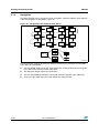
Software debug is done via the standard ARM® JTAG connection: 20-pin IDC (insulation
displacement connector) for connection to the standard ARM host interface.
1.5
Serial wire debugger interface
The Serial Wire Debug Port (SWD-DP) provides a 2-pin (clock + data) interface to the AHPAP port.
1.6
Embedded ST-LINK
An ST-LINK is integrated on the board as an embedded in-circuit debugger and programmer
for the STM32F30x/31x MCU.
1.7
Display devices
1.7.1
LCD
A TFT color LCD module is mounted on the STM32303C-EVAL board. It is interfaced
through the embedded SPI peripheral.
1.7.2
LEDs
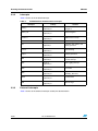
Four general-purpose LEDs are available. They are used as a display.
1.7.3
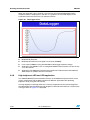
LDR (Light Dependent Resistor)
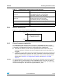
The VDDA supply is divided by a resistor bridge of LDR VT9ON1 and 8.2 KΩ resistor and
connected to PA0.
8/65
Doc ID 023892 Rev 1