1
SCOOP 4+
Stereo audio codec for real time audio transmission
User manual
AETA AUDIO SYSTEMS
18-22, avenue Edouard Herriot - Kepler 4
92350 Le Plessis Robinson – FRANCE
Tél. +33 1 41 36 12 00 – Fax +33 1 41 36 12 69
http://www.aeta-audio.com
55 000 053 - F
Specifications subject to change – All rights reserved by AAS
SCOOP 4+ - User manual
February 2010
55_000_053-f_scoop4_en.docx
Table of contents
1.
General ............................................................................................................................... 1
2.
Functions ............................................................................................................................ 3
2.1. Conversion of audio signals ......................................................................................................... 3
2.2. Encoding and decoding ................................................................................................................ 4
2.3. Transmission interfaces ................................................................................................................ 7
2.4. Supervision and control interface ................................................................................................. 9
2.5. Audio monitoring ....................................................................................................................... 10
2.6. Auxiliary functions ..................................................................................................................... 11
3.
Operation ......................................................................................................................... 13
3.1. General principles....................................................................................................................... 13
3.2. Physical description of the equipment........................................................................................ 14
3.3. Equipment configuration parameters ......................................................................................... 21
3.4. Installation and set up ................................................................................................................. 23
3.5. Initial setup of the Ethernet interface ......................................................................................... 24
3.6. Use of the embedded html server ............................................................................................... 26
3.7. First level maintenance ............................................................................................................... 30
4.
Detailed operating mode – User interface .................................................................... 32
4.1. Main operation modes ................................................................................................................ 32
4.2. Equipment start-up ..................................................................................................................... 32
4.3. Description of the keyboard ....................................................................................................... 33
4.4. Description of the menus ............................................................................................................ 33
4.5. Handling the configuration profiles ........................................................................................... 40
4.6. Setting up a link in ISDN mode ................................................................................................. 41
4.7. Setting up a link in IP mode ....................................................................................................... 43
4.8. Auto-redial feature ..................................................................................................................... 46
4.9. Loop control ............................................................................................................................... 46
4.10. Setting up a backup link ........................................................................................................... 47
4.11. Erasing and resetting the configuration .................................................................................... 49
4.12. Backing up and recalling the configuration.............................................................................. 49
5.
Technical characteristics ................................................................................................ 50
5.1. Characteristics of interfaces ....................................................................................................... 50
5.2. Audio performance ..................................................................................................................... 57
5.3. Network protocols and ports ...................................................................................................... 58
5.4. Power supply .............................................................................................................................. 58
5.5. Dimensions and weight .............................................................................................................. 58
5.6. Environmental characteristics .................................................................................................... 59
5.7. Versions - Options ...................................................................................................................... 59
5.8. Accessories and related products................................................................................................ 59
55 000 053 - F
SCOOP 4+ - User manual
6.
Annexes ............................................................................................................................ 60
6.1. Complements on the algorithms and protocols used .................................................................. 60
6.2. Overview of the SIP protocol ..................................................................................................... 61
6.3. Some methods to deal with NAT routers and firewalls .............................................................. 63
6.4. ISDN error causes....................................................................................................................... 68
6.5. V35 interface adaptation............................................................................................................. 70
6.6. Notice regarding open source code ............................................................................................ 71
6.7. Index ........................................................................................................................................... 72
SCOOP 4+ - User manual
55 000 053 - F
1. General
The SCOOP 4+ codec allows the bi-directional transmission of one or two audio signals with bit rate
reduction, over digital leased lines, ISDN lines or IP protocol networks. The codec is available with the
following main product versions:
SCOOP 4+ DUO LL/IP, with digital leased line interfaces and an Ethernet interface for IP
transmission;
SCOOP 4+ TRIO LL/IP/ISDN 2B, with digital leased line interfaces, Ethernet interface and an
ISDN interface;
SCOOP 4+ TRIO LL/IP/ISDN 4B, with digital leased line interfaces, Ethernet interface and two
ISDN interfaces.
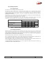
The following table shows the main features of the product. Functions marked with in this table are
available as options. Functions marked with □ are only available in the versions equipped with ISDN
interface(s).
One outstanding feature of AAS codecs in ISDN mode is the 5A System: on receiving an incoming
ISDN call, the unit can automatically detect the coding algorithm and parameters of the calling codec, and
then adjust itself in a compatible configuration so that the connection succeeds regardless of the initial
configuration and that of the remote unit.
In IP mode, the codec features the same ease of operation thanks to the use of the SIP and SDP protocols.
The standard operation mode is the “single codec” mode, where the unit can be connected to a remote
codec using any one of the listed coding algorithms.
In the dual 7 kHz codec mode (available for leased line transmission), the equipment is equivalent to two
independent mono codecs, each running G722 over a 64 kbit/s leased lines.
Such a dual codec mode is also available for ISDN transmission; in this case the equipment is equivalent
to two independent mono codecs, each running G711 or G722 over one B channel of the ISDN interface.
5AS = Aeta Audio Advanced Automatic Adjustment System
55 000 053 - F
SCOOP 4+ - User manual
1
Characteristics
Optional
Operation modes
Single wide band codec
Dual 7 kHz codec (LL mode or ISDN mode)
IP transmission interface
Ethernet interface, 10BaseT / 100BaseT; TCP/IP and UDP/IP protocols
Audio transmission in unicast mode: SIP signalling protocol, SDP protocol
Audio transmission in multicast mode
Leased line transmission interfaces
Two X24/X21/V11/V35 interfaces;
64, 128, 192, 256 or 384 kbit/s over one line, or 2x64 kbit/s over two lines
ISDN transmission interface
One or two S0 interfaces (U interfaces available for North America)
5AS automatic setting for incoming calls
□
(audio modes)
Audio coding algorithms
G711 (standard telephone)
Mono
G722 SRT, H221, H242
Mono
CELP 7 kHz (IP mode only)
Mono
MPEG Audio Layer II
Mono, Stereo, Dual mono, Joint stereo
MPEG AAC-LC
Mono, Stereo
MPEG HE-AAC, HE-AAC v2
Mono, Stereo
4 sub-band ADPCM (low latency)
M, S
TDAC (ISDN mode only)
M
□
Available bit rates (depending on coding algorithm):
Leased line transmission: 64 to 384 kbit/s over one line, or 2x64 kbit/s over two lines
IP transmission: 16 kbit/s to 256 kbit/s
ISDN: 64 to 256 kbit/s transmitted via one or two interfaces (1 to 4 B channels)
□
Audio interfaces
Two analogue inputs and two analogue outputs with adjustable level
Digital audio input and output, AES/EBU format
Auxiliary functions
Data channel, 300 to 9600 bauds
Relay transmission: 2 isolated inputs and outputs
Audio coordination channel
Control and supervision
Keyboard and LCD display on front panel
99 programmable set-up/dial memories
Remote control serial port
Ethernet remote control interface
Embedded html server
Isolated control and status loops
Table 1 – Main features of the SCOOP 4+
2
SCOOP 4+ - User manual
55 000 053 - F
2. Functions
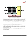
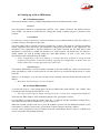
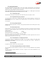
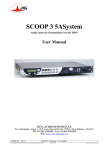
The following synoptic diagram shows the basic functions of the equipment.
Figure 1 - Functional diagram of equipment
The audio signals to be transmitted are converted (when needed) to digital format, then the encoding
function reduces the bit rate, using a selectable algorithm; the resulting bit flow is sent to one of the
available transmission interfaces: permanent link data interfaces (X21/X24/V35), ISDN interfaces (S0 or
U0), or an Ethernet interface.
The transmission interface functional block also extracts compressed data coming from the network and
sends them to a decoding block that reproduces uncompressed audio data. Last, the audio signals are
output to both digital and analogue outputs.
2.1. Conversion of audio signals
The analogue inputs and outputs are balanced, and the input and output gains are adjustable. The
sampling frequency of the analogue digital converters depend on the operating mode.
The equipment also provides digital audio inputs/outputs in AES/EBU format. The input to the encoder is
selectable between the digital audio input and the analogue stereo input. The output from the decoder is
sent both to the digital output and the analogue stereo output. The digital audio interfaces are usually
locked to the digital audio input (“genlock” mode), but alternatively they can be synchronised to the
internal clock reference of the codec.
Having the digital samples from the audio interfaces (analogue or digital), sample rate conversion is
fulfilled whenever needed to get audio data at the coding frequency Fc which is, depending on the coding
type, 16, 24, 32 or 48 kHz.
55 000 053 - F
SCOOP 4+ - User manual
3
2.2. Encoding and decoding
In the normal single codec mode, the codec readily includes a wide range of coding algorithms. First, one
can select among algorithms compliant with ISO and ITU-T recommendations:
G711 (IP or ISDN mode only);
ITU-T G722 (mono at 64 kbit/s);
MPEG Audio Layer II at 48, 32, 24 or 16 kHz, with programmable channel mode and bit rate ;
MPEG AAC-LC at 48 or 32 kHz, programmable channel mode and bit rate; available as an
option, for IP and ISDN modes;
MPEG HE-AAC and HE-AAC v2 at 48 or 32 kHz, programmable channel mode and bit
rate; available as an option1 for IP and ISDN modes;
Besides, other algorithms are available, that are so-called “proprietary” because they do not comply with
enforced standards:
CELP, running in mono at a net 24 kbit/s bit rate, and providing a 7 kHz bandwidth (only used in
IP mode);
4SB ADPCM, running either in mono at a 128 kbit/s bit rate, or in stereo at 256 kbit/s; the
bandwidth with this algorithm is 15 kHz.
TDAC mono, running at 64 kbit/s, with a 15 kHz bandwidth; available as an option in ISDN
mode.
In the dual 7 kHz codec mode, each codec (or audio channel) can be encoded using the following
algorithms:
G711; which is the standard coding for voice transmission on the ISDN (this algorithm is not
available in LL mode);
ITU-T G722, running in mono at a 64 kbit/s rate.
The following describes some important features of the various available algorithms and protocols.
2.2.1. Notes about G711
G711 is the standard coding used for voice transmission on public telephone networks. This algorithm is
typically used for links over IP networks with IP telephones or VoIP gateways. Via ISDN, G711 is used
for links with telephones or hybrid devices.
G711 is available only for IP or ISDN transmission, not over the leased line interfaces.
2.2.2. Notes about G722
With G722 coding, three synchronisation modes are available:
“Statistical recovery” byte synchronisation method (alias SRT) ;
H221 synchronisation; in this case, 1.6 kbit/s from the compressed data are used for this;
H221 synchronisation and H242 protocol. This is only available for the ISDN mode.
H221 synchronisation is highly recommended when possible, as it features higher reliability and faster
recovery time, while degradation (because of the bit rate used for framing) is minimal.
H242 protocol, the most flexible mode, is recommended by the ITU-T, and is included in J52. However,
the mode with H221 synchronisation but without H242 protocol can be useful for compatibility with old
generation codecs which did not use this protocol.
No specific synchronisation is needed for the IP mode.
1 Not available for first generation units
4
SCOOP 4+ - User manual
55 000 053 - F
2.2.3. Notes about MPEG coding and J52
The ITU-T J52 recommendation was defined in order to allow the interoperability of multimedia
terminals over the ISDN1, using common coding standards. It includes the following features:
Framing as per ITU-T H221 recommendation, ensuring byte synchronisation and interchannel
synchronisation when more than one 64 kbit/s B channel is required for the desired bit rate ;
Interoperation procedures according to ITU-T H242 recommendation ;
In the case of MPEG encoding, optional protection against transmission errors (Reed-Solomon
error correction codes). Although J52 does not apply to leased line connections, this error
protection technique is also available for leased line transmission with the SCOOP 4+.
Details about MPEG and J52 can be found in the annexes (refer to 6.1, Complements on the algorithms
and protocols used).
It must be noted that, thanks to the interoperation protocol, J52 codecs, when setting up a link, can
negotiate automatically and agree on a configuration that is compatible with the capability of both units
(regarding bit rate, channel mode, etc.). In this way, when the units differ in their capability (or make), the
resulting configuration may be different from expected beforehand, but in most cases the link will work
and audio will be transmitted.
As another useful consequence, this also gives users more tolerance to mistakes when configuring the
units on the two sides of the transmission links, as the codecs will adapt automatically even with
differences in the initial settings of the two units.
2.2.4. MPEG coding for leased line or IP transmission
J52 is only applicable to ISDN transmission, and no inverse multiplexing is needed for leased line
transmission neither for IP transmission, because a single data stream is transmitted.
For these reasons, only one MPEG format is defined for non-ISDN transmission; there is no distinction in
these modes between J52-compliant or non compliant format.
2.2.5. Notes about TDAC
As an option, the codec can also include the TDAC algorithm. TDAC is for Time Domain Aliasing
Cancellation ; this is a transform coding based on an MDCT (Modified Discrete Cosine Transform),
encoding a 15 kHz bandwidth mono signal at a 64 kbit/s bit rate.
Some specific product versions also include “asymmetric” modes:
G722/TDAC : G722 encoding, TDAC decoding, running both in mono at 64 kbit/s ;
TDAC/G722 : TDAC encoding, G722 decoding (with SRT), running both in mono at 64 kbit/s ;
this mode is symmetric to the previous one.
1 J52 is only relevant for ISDN connections
55 000 053 - F
SCOOP 4+ - User manual
5
2.2.6. Symmetric or asymmetric codec modes
The codec allows two communication modes:
Symmetric communication: in this mode, the encoder and decoder both use the same coding algorithm
with the same configuration (channel mode, etc.). In this case, the communication is strictly symmetric
full-duplex, with exactly the same coding configuration used in both directions (local to remote and
remote to local). This is usually required when using proprietary algorithms.
Asymmetric communication: this mode is used for applications requiring different coding configurations
in the two directions. The J52 protocol allows such mode. To give some examples, it is possible to
transmit MPEG Layer II in one direction and G722 in the other one, or MPEG stereo in one direction and
MPEG mono in the other one, etc.
Specific product versions also allow asymmetric modes wherein one direction is G722 coded while the
other one is TDAC coded. Such mode is useful e.g. in order to get a low delay return path encoded in
G722 while the send path is encoded with higher quality but a higher delay.
2.2.7. 5A System®
Setting an ISDN connection is often difficult, at least because of the numerous coding parameters to be
set. Moreover, with most proprietary algorithms, it is mandatory for the two devices to have exactly the
same settings, otherwise the connection will fail, and sometimes it is not easy to find out the reason.
5A stands for Aeta Audio Advanced Automatic Adjustment. This system makes it easier to set an ISDN
connection, because the codec, on receiving a call, automatically adjusts itself, following the calling party
algorithm and parameters.
When the 5A System is enabled on the unit and a call is received, the unit first detects the coding
algorithm used by the calling codec, and also senses its parameters: audio mode (mono, stereo…),
sampling rate, bit rate, inverse multiplexing protocol, etc. Then the unit can decode the compressed audio
from the remote unit. In addition, the unit will use these same settings for encoding and sending audio to
the remote unit, so that the remote unit can also decode the outgoing audio programme. The whole
process just takes a few seconds. Of course, all compatible coding configurations can be detected
automatically by the 5A System.
Note that the 5A system is only active for ISDN connections.
2.2.8. SIP protocol and SDP
The SIP protocol is a signalling protocol, used for IP connections, which allows the SCOOP4+ to
interoperate with IP phones and other SIP compatible audio codecs, in a way similar to ISDN or POTS
connections. Details about the SIP protocols can be found in the annex (refer to 6.2, Overview of the SIP
protocol).
One significant advantage is the inclusion of SDP, a protocol which allows the connecting devices to
automatically negotiate and agree on the coding profile to use. Thanks to this system, it is not necessary
to set the units in the same way before setting up a connection. Moreover, the calling party need not know
how the remote unit is configured before initiating a link.
Note: the SIP protocol does not mandatorily imply the use of a server. Codecs can set up point-topoint links using this protocol, and benefit from some advantages of this protocol.
6
SCOOP 4+ - User manual
55 000 053 - F
2.3. Transmission interfaces
The codec includes an Ethernet interface for IP protocol networks, interfaces for transmission over leased
lines, and one or two ISDN interfaces are available in some versions.
2.3.1. Ethernet/IP interface
The IP interface is a 10BaseT/100BaseT Ethernet interface allowing transmission of the audio
programmes in a wide range of possible bit rates.
IP unicast mode
The most classical transmission mode is unicast: audio connection with one distant device, generally
bidirectional. This mode can be used on all types of networks links, LAN or WAN, including links via
Internet. The SCOOP 4+ implements the SIP protocol, which allows it to interoperate with IP phones and
other SIP compatible audio codecs, in a way similar to ISDN or POTS connections. Links can be set up in
two ways:
“Peer to peer” connection between two compatible units
Use of a SIP proxy server to set up the link, or a SIP PBX
Details about the SIP protocols can be found in the annex (refer to 6.2, Overview of the SIP protocol).
The audio coding algorithm can be selected depending on the required quality and the available network
bandwidth. The following algorithms are currently available:
Codec
Bit rate
(coding)
Bit rate
(total)1
Audio
bandwidth
G711
64 kbit/s
86 kbit/s
3 kHz
Voice,
Compatible with IP phones
CELP
24 kbit/s
28,5 kbit/s
7 kHz
Suitable for high quality speech;
Low network bandwidth consumption
G722
64 kbit/s
86 kbit/s
7 kHz
High quality speech
MPEG Layer II
64 or 128
kbit/s
16 à 192
kbit/s
83 to 147
kbit/s
30 to 213
kbit/s
up to
20 kHz
up to
20 kHz
Highest quality, suitable for speech and
music
Low bit rate, suitable for speech and
music
MPEG HE-AAC
and HE-AAC v2
16 to 128
kbit/s
23 to 139
kbit/s
up to
20 kHz
Very low bit rate, suitable for speech and
music
4SB ADPCM
64 or 128
kbit/s
173 or
301 kbit/s
15 kHz
Low latency, suitable for speech and
music
MPEG AAC-LC
Typical use, main features
telephony
IP multicast mode
The multicast mode allows an encoder device to transmit an audio programme to several decoders by
sending a single encoded stream to a multicast group address. The link is unidirectional by nature. This
mode can be used on a local area network, and on larger private networks that can manage the multicast
mode. On the other hand, Internet cannot support this routing mode.
1 Informative value; higher than the “net” encoded audio bit rate because of the protocol overhead
55 000 053 - F
SCOOP 4+ - User manual
7
In this mode, SCOOP 4+ uses the RTP protocol to manage the audio stream, like in the unicast mode, but
the SIP protocol is not applicable here; instead a proprietary signalling system is used. As the link is
unidirectional, the unit has to be set either as a “sender” in order to encode and transmit the audio stream
to the selected group address, or as a “receiver” to receive and decode such stream coming from a
“sender” device.
The audio coding algorithm can be selected with just the same capability as for the unicast mode
described above.
Remote control via IP
In addition, the Ethernet interface can be used for configuring or remote controlling the unit via a TCP/IP
connection.
An embedded web server allows configuring some parameters using a web browser, via port 80
(default port for the HTTP protocol);
TCP port 6000 can be used for a “command line” control mode, typically used by codec
supervision software.
2.3.2. Leased line interfaces
For transmission over leased lines, the codec includes two X24/V11 ports which can run at 64 kbit/s,
128 kbit/s, 192 kbit/s, 256 kbit/s and 384 kbit/s bit rates.
With most coding modes, only one X24/V11 port is used. In the “2*64” dual mono G722 mode, the two
ports provide two independent interfaces; the equipment is similar to two mono codecs.
When transmitting in the “leased line” mode, the codec synchronises onto the network clock provided by
the X24/V11 interface. In the specific “2*64” mode where the two ports are used, the codec initially
synchronises on port #1, but it changes the synchronisation port in case of a fault.
If no valid clock is available on the X24/V11 interfaces, the system folds back to an internal clock.
2.3.3. ISDN Interface
On the ISDN side, the codec includes one or two BRI interfaces (S0 or U0 depending on equipment
version), allowing transmission over one to four 64 kbit/s B channels. Thus, the total available bit rate
ranges from 64 to 128 kbit/s.
The codec synchronises itself onto the ISDN network clock when a link is active.
2.3.4. Use of a backup connection to secure a permanent link
When a fixed link (LL) is used, it is possible to use another network access (IP or ISDN) in order to set a
temporary backup link in case the nominal LL link fails. The unit will then switch to a backup mode
(ISDN or IP depending on the selected backup arrangement), and provide the audio transmission via the
backup network access. More precisely, on one end of the link the codec will switch to the backup mode
and “call” its counterpart via the ISDN or and IP network. On the other end the unit will switch to the
backup mode when it receives the call on its ISDN or IP interface. The operating mode and configuration
for this backup feature are detailed further in following sections (4.10, Setting up a backup link).
8
SCOOP 4+ - User manual
55 000 053 - F
2.4. Supervision and control interface
These functional modules fulfil the control and supervision of the equipment (configuration,
communication management, status monitoring), thanks to a keyboard, an alphanumeric display, LED
indicators, and remote control interfaces.
The remote control is possible either via a serial data port or through the Ethernet interface with a TCP/IP
connection.
In addition, the equipment features a “Loop control” function: call set up and release can be remote
controlled with current loops and relays, instead of using for this the keyboard and/or the remote control
port.
In order to allow easy and quick programming of the codec for specific operational configurations, the
equipment features configuration memories (or “profiles”). When recalling a profile, the codec is directly
reconfigured with parameters that were stored beforehand in this profile by the operator, and/or the stored
number is dialled by the unit.
Besides configuring the equipment operating mode, this module monitors its status (detection of alarm
conditions). On detecting operation or transmission faults, the equipment switches on indicators and relay
contacts. Two alarm classes are defined:
“Internal” alarm ; corresponds to a major fault internal to the equipment ;
“External” alarm ; corresponds to a fault whose origin is deemed external to the equipment (for
example, transmission fault);
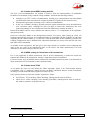
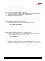
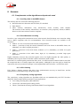
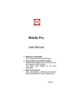
For maintenance purposes, some test loops can be activated:
“Audio loop”: uncompressed audio data are looped from the input of the encoder to the input of
the output conversion functional block. This loop redirects the audio input to the audio outputs;
“Loop 3”, or “Codec” loop: compressed audio data are looped just before the network interface ;
“Loop 2”, or “Network” loop: this loop sends the received data back to the network ; for the
remote codec, the effect is the same as a loop 3 when the transmission works correctly ;
“Audio feedback” loop (audio output to audio input) ; this allows the codec to send back to the
remote codec the signal it receives, after decoding and re-encoding.
The following drawing schematically shows the test loops:
55 000 053 - F
SCOOP 4+ - User manual
9
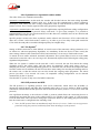
2.5. Audio monitoring
This function enables the monitoring of the audio input (before encoding) and the audio output (after
decoding the received signal), and provides:
A display of the signal level both at the encoder input and the decoder output ;
A test output on a stereo headphone jack, monitoring either the encoder or decoder audio signals.
Note: as the audio output is monitored immediately after decoding, this monitoring position is not
sensitive to the possible activation of the audio test loop (see above diagram), contrarily to the
physical audio outputs (both analog and digital).
10
SCOOP 4+ - User manual
55 000 053 - F
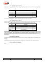
2.6. Auxiliary functions
2.6.1. Data channel
This function is not available in IP transmission mode.
In leased line mode or ISDN mode, a bi-directional data channel can be transmitted along with the
compressed audio signals, by reserving a fraction of the transmitted bit rate. The equipment includes a
serial asynchronous port for this purpose. The data are transparently transmitted end-to-end; hardware
signalling is not available.
This function is only available when the main audio programme is encoded in G722 H242 (ISDN mode),
MPEG (excluding the proprietary ISDN mode) or ADPCM.
The interface speed is programmable at 300, 1200, 2400, 4800 or 9600 bauds. However, the actual
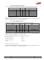
transmission capacity depends on the coding algorithm, as indicated by the table hereunder.
Coding type
Possible transmission rate (bit/s)
300
1200
2400
4800
9600
G722 (H221/H242)
MPEG Audio
4SB ADPCM
Table 1 – Capacity of data channel depending on type of coding
2.6.2. Relay transmission
When this function is activated, the codec transmits to the remote unit the status of two isolated current
loops. The remote unit then opens or closes relay contacts according to the transmitted status. Conversely,
as the function is bi-directional, the codec activates its two relays (“dry” isolated contacts) depending on
the status of the two current loops on the remote unit.
In IP transmission mode, this function is available whatever the selected coding.
In LL or ISDN mode, this function is only available when the main audio programme is encoded in G722
H242 (ISDN mode), MPEG (excluding the proprietary ISDN mode) or ADPCM.
When using MPEG coding, relay transmission can be activated along with other auxiliary functions. For
G722 or ADPCM, relay transmission is activated in place of the data channel.
A typical application is the transmission of an “on air” signal; the contact closure may be used for e.g.
switching on a lamp or starting other devices.
55 000 053 - F
SCOOP 4+ - User manual
11
2.6.3. Coordination channel
This function is currently only available in leased line transmission mode.
This function is available as an option. It enables the transmission of an auxiliary audio channel (or
coordination or “order-wire” channel), along with the compressed audio, by reserving 8 kbit/s from the
transmitted bit rate. This channel uses a compression algorithm of CELP-HLTP type and provides a
“voice grade” channel (300-3400 Hz pass-band).
This function is only available when the main audio programme is encoded in G722 H242 (ISDN mode),
MPEG (excluding the proprietary ISDN mode) or ADPCM.
With G722 or ADPCM, the coordination channel cannot be used along with other auxiliary functions (i.e.
data channel or relay transmission).
When using MPEG coding, all three auxiliary functions can be activated at the same time. Note that relay
transmission and the coordination channel are only compatible with AAS products, as these functions are
not covered by independent standards.
12
SCOOP 4+ - User manual
55 000 053 - F
3. Operation
3.1. General principles
The equipment control and supervision (configuration, status monitoring) is possible in two ways:
“Local” mode: front panel keyboard and display, status indicators ;
“Remote control” mode, thanks to an asynchronous serial port or the Ethernet interface.
As a general rule, the configuration parameters are saved in non-volatile memory, and restored when the
unit is powered-on.
Local mode operation is described in detail in chapter 4 (Detailed operating mode).
Thanks to the remote control mode, the codec can be operated from a computer with supervision
software. The supervision station is a PC computer running Windows, equipped with the Scoop4Man
configuration and monitoring software. This software gives full access to the codec functions
(configuration, audio link management and status monitoring) with a graphical interface.
Scoop 4+ can also be controlled by the optional software TeleScoop, which can control the other AAS
codecs of the Hifiscoop, Scoop 3 and Hifiscoop 3 ranges. Details about this supervision software can be
found in the documentation and user manual of the TeleScoop software.
In addition to this, some parameters related to the Ethernet/IP interface and transmission can be set by
using an embedded HTML server; these are described further in 3.6, “Use of the embedded html server”.
For controlling connections in ISDN or IP mode, it is also possible to use the “Loop control” function.
When this special connection mode is selected, one can trigger a call by activating an input current loop
(optically isolated), and release the line by de-activating this loop. In such case, an outgoing connection is
established or released only by this way, and no more from the front panel or the remote control interface
(however, all other parameters are still controlled from these interfaces as in the normal mode).
If “loop control” is not activated, it is always possible to use the loop to release a running connection (a
pulse on the loop will release the line).
Besides, whatever the connection mode (normal or loop control), a “dry loop” is closed when a
connection is active.
The loop control interfaces are described in 3.2.2 and 5.1.13.
The SCOOP 4+ can be remote controlled by third-party codec management software and systems. Please
consult us for more information on the available offer in this field.
55 000 053 - F
SCOOP 4+ - User manual
13
3.2. Physical description of the equipment
The SCOOP 4+ codec is housed in a 19 inches chassis of 1U height (44 mm or 1.75”). It includes a
universal mains power supply, or optionally it can be powered from a 12V DC source.
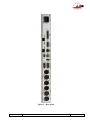
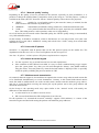
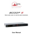
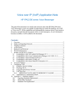
3.2.1. Front panel
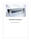
All the elements needed for local control are located on the front panel (see picture on page 16 below).
This panel can be roughly divided in three areas:
On the left-hand side, one can find an LCD and the basic navigation and dialling keys. The central area of
the panel includes several status LEDs and a keypad for the entry of dialling numbers and/or text data.
The right hand side groups audio monitoring elements.
The “Esc” key is also used to power the unit on and off:
When the unit is in standby (the blue LED besides the Esc key is on), hold the key depressed for at
least 3 seconds to switch the unit on;
When the unit is in operation, press the key down for more than 3 seconds to switch it off.
In addition to this “soft” switch, the unit automatically switches on when AC power is applied to its
power socket.
LCD and basic control keypad
This part is used for configuration and call set up; details cane be found in chapter 4, dealing with the
operating mode.
The 2x20 character alphanumeric display is surrounded by the following keys, (from left to right):
Key
“Hang up”
Function
Release a link in IP or ISDN transmission mode
Start a link or accept an incoming call (in IP or ISDN transmission
mode)
“Unhook”
Navigation keys
Menu-dependent keys; used to scroll options and/or select an option in a
menu. The bottom line on the LCD shows the function of each key.
“OK” key
Confirm a selection or enter data
“Esc” /
key
Short pressure: Escape to higher menu level;
Long pressure: Switch on or switch off the unit1
The blue LED besides the Esc/Power key is off in operation, but lights on when the unit is in standby.
1 Note: the standby mode can be disabled by internal configuration; in such case a long pressure has no effect!
14
SCOOP 4+ - User manual
55 000 053 - F
Status LED indicators
The LEDs have the following meaning (from left to right):
Marking
Color
blue
Function
On when unit is in standby
Line 1
Green
On when interface n°1 is active / connected
Line 2
Green
On when interface n°2 is active / connected
Dec 1
Green
On when the decoder is synchronised on “line 1”
Dec 2
Green
On when the decoder is synchronised on “line 2”
INFO 1
Amber Displays the status of the received “relay info” n°1
INFO 2
Amber Displays the status of the received “relay info” n°2
Test
Red
On whenever a test loop is active
Alarm / Ext
Red
On in case of an external alarm
Alarm / Int
Red
On in case of an alarm with internal cause
55 000 053 - F
SCOOP 4+ - User manual
15
Figure 2 - Front panel of SCOOP 4+
16
SCOOP 4+ - User manual
55 000 053 - F
Audio monitoring
Two pairs of LED bargraphs display the level of the audio signals, both on the transmission and reception
directions. The top bargraphs display the level of the audio channels on the transmitter (encoder), while
the bottom bargraphs display the level of the received channels (decoder side). The 0 dB mark is a
reference level that can be adjusted (relatively to digital full scale; the reference level can be set in the
menu, SETUP / Audio / Level Meter / HEADROOM). The “OVLD” LED at the right end of each bar
shows when the signal reaches maximum digital level (or clipping level), regardless of the reference level
setting.
“OVLD” always reacts to absolute full scale level, while the bargraph level indication depends
on the reference level setting
The “HEADROOM” setting in the menu defines (in dB) the difference between the maximum level (or
digital full scale) and the reference level, for which 0 dB is displayed on the level meters. Here are some
examples:
If the headroom is set at 0 dB, then the maximum displayed level is 0 dB; note that OVLD will
light on whenever the signal reaches this level (or exceeds it on the analogue input).
If the headroom is set at 10 dB, then “0 dB” is displayed when the signal is 10 dB below
maximum level, or -10 dBFS. The display in such case can reach up to +5 dB. OVLD lights up
when the signal reaches maximum level (but not before!).
The audio signals can also be monitored with a headphone connected on the front panel (1/4” or 6.35 mm
stereo jack). The headphone volume is adjustable thanks to a potentiometer, and the source select key
toggles the listening between transmission (Tx indicator) or reception (Rx indicator).
Actions dealing with this area (connecting or disconnecting the jack, Tx/Rx selection, volume adjustment)
never affect the transmitted or received signals.
55 000 053 - F
SCOOP 4+ - User manual
17
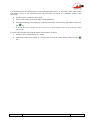
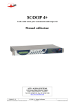
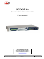
3.2.2. Rear panel
All connections are done on the rear panel of the codec. The characteristics of the interfaces and layout of
the sockets are detailed in chapter 5.1. Characteristics of interfaces.
The following elements are available on the rear panel (refer to following Figure 3 - Rear panel):
Mains power socket
This is an IEC type power socket.
The “12V DC” version of the product includes, in place of this AC power socket, a 4-pin male XLR
socket for an external DC source. Refer to details in 5.1.14, Connector for DC input (option).
Audio inputs/outputs
Analog inputs/outputs: at the input, plug the audio cables into the female XLR sockets. At the
output, plug the audio cables into the male XLR sockets. In mono mode, only “A” channel is
used.
Digital inputs/outputs: a digital input (mono or stereo) in AES/EBU format (or SPDIF) can be
connected on the female XLR socket, and a digital output in AES/EBU format is available on a
male XLR socket.
It is possible to select which input (analog inputs or digital input) is fed to the encoder for
transmission. On the receiving side, the decoded signals are output both on the analog and digital
outputs.
X24/V11/V35 interfaces (labelled “X24/V11/V35” and “ALARM + X24/V11”)
These sockets are used for the connection to data transmission equipment in the “leased line” mode.
The connectors are 15-point male, Sub-D type. In the standard single codec mode, only one port is used.
This is normally the main port “X24/V11/V35”, but it is possible to select the other port.
In the dual codec mode, both ports must be used. In this mode, audio channel A is transmitted on the
main port “X24/V11/V35”, and audio channel B is transmitted on the additional port labelled
“ALARM + X24/V11”.
Alarm indicator and contacts
This “ALARM + X24/V11” port also includes two “form C” relays, providing isolated contacts, which
can signal alarm conditions:
Internal alarm contact;
External alarm contact;
A red LED indicator also indicates that an alarm relay is activated. In the factory setup, every alarm cause
sets the LED on, but by setting jumpers on the motherboard it is possible to program the indicator to react
to only one type (internal or external alarm).
The pin-out of the socket and the detailed characteristics of the alarm relays can be found in chapter 5.1.6:
“Alarm + X24/X21” interface (p. 51).
USB socket
This host USB port is currently not used.
18
SCOOP 4+ - User manual
55 000 053 - F
Figure 3 - Rear panel
55 000 053 - F
SCOOP 4+ - User manual
19
Remote control (Remote)
This 9-pin female sub-D socket is an asynchronous serial interface port, usable for remote controlling the
equipment thanks to a control and supervision PC.
Data
This 9-pin female sub-D socket is an asynchronous serial interface port, usable for transmission of a bidirectional data channel (refer to 2.6.1 above, Data channel).
Ethernet interface
This socket is a 100BaseT/10BaseT port, used for audio transmission over IP and/or for remote
controlling the unit via a TCP/IP connection (TCP port: 6000). This RJ45 socket is devised for a normal
“straight” cable to an Ethernet hub or switch. The two integrated LEDs show the presence and activity of
the network (green LED) and the interface mode: half-duplex (yellow LED off) or full-duplex (yellow
LED on).
The configuration of the interface is described in 3.5, Initial setup of the Ethernet interface.
“ISDN 1” and “ISDN 2” sockets
These RJ45 sockets allow the connection to the ISDN, for the product versions which include this
capability. Their layout is standard. The sockets must be used according to their number, i.e. #1 must be
used if one line only is needed, #1 and #2 if two lines are needed.
“Digital I/O” socket
Reserved for future use.
“AUX” socket
This 25-pin female sub-D socket groups the interfaces for the relay transmission function and the
(optional) coordination audio channel.
It also includes loop interfaces for the loop control function, as well as a +5 V power supply that can be
used to provide current for the loop and relay interfaces.
20
SCOOP 4+ - User manual
55 000 053 - F
3.3. Equipment configuration parameters
The parameters may be divided into the following categories:
Coding configuration parameters, which include audio coding type, coding frequency Fc (and
subsequently the nominal bandwidth), audio channel mode and transmission bit rate. Besides, in
case of MPEG coding, it is possible to select the error protection mode.
Configuration of the audio interfaces, including: selection of analogue or digital format for the
audio input, maximum level for the analogue inputs and outputs, and synchronisation mode for
the AES/EBU interfaces.
Parameters of the auxiliary functions: possible activation of a data channel, bit rate of this,
possible activation of the relay transmission, possible activation of the auxiliary audio channel (if
this option is available).
Parameters of the network access: type of network interface (Ethernet/IP, leased line or ISDN),
interface parameters, etc.
Parameters of the keyboard/display interface (as an example, selection of the language for the
display messages).
Chapter 4 (Detailed operating mode) describes these two last categories.
The parameters dealing with the audio interfaces are programmable independently from the others. On the
other hand, the auxiliary functions depend on the current transmission mode and coding type.
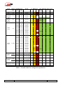
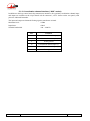
The following table is a summary, for each coding type, of the allowed values for the various parameters
of the coding configuration and auxiliary functions.
Meaning of abbreviations in the table:
Channel mode : M = Mono, S = Stereo, JS = Joint stereo, DM = Dual Mono
Coding : H221 = H221 synchronisation, SRT = Statistical Recovery Timing
4B = only available on 4B equipment version (two ISDN interfaces)
FEC : Forward Error Correction = Reed-Solomon error correction
Only MPEG can be configured with all three auxiliary functions (data, auxiliary audio, relays). For other
algorithms, each function, when available, can only be used alone. Auxiliary functions are only available
for codec 1 when in double codec configuration.
Regarding the auxiliary functions, the table does not apply to the IP mode, in which:
The data channel and the auxiliary audio are not available;
The relays are always available, regardless of the coding algorithm used.
The (optional) MPEG AAC coding, in all its variations, is very flexible regarding the bit rate
selection in IP transmission mode. To preserve readability, this table does not give the exhaustive
list of all available bit rates. However, for ISDN transmission only 64 and 128 kbit/s are allowed.
55 000 053 - F
SCOOP 4+ - User manual
21
Coding
G711
CELP
G722 (SRT)
G722 H221
G722 H242
4SB
ADPCM
4SB
ADPCM
MPEG
Layer II
MPEG
Layer II
MPEG
AAC-LC
MPEG
HE-AAC
Channel Sampling
mode
rate
Bandwidth
Bit rate
8 kHz
16 kHz
16 kHz
16 kHz
16 kHz
3,4 kHz
7 kHz
7 kHz
7 kHz
7 kHz
64 kbit/s
24 kbit/s
64 kbit/s
64 kbit/s
64 kbit/s
M
32 kHz
15 kHz
128 kbit/s
S
32 kHz
16 kHz
16 kHz
24 kHz
24 kHz
32 kHz
32 kHz
32 kHz
48 kHz
48 kHz
48 kHz
16 kHz
16 kHz
24 kHz
24 kHz
32 kHz
32 kHz
32 kHz
32 kHz
32 kHz
48 kHz
48 kHz
48 kHz
48 kHz
48 kHz
32 kHz
48 kHz
32 kHz
48 kHz
32 kHz
48 kHz
32 kHz
48 kHz
32 kHz
48 kHz
32 kHz
15 kHz
7 kHz
7 kHz
10 kHz
10 kHz
15 kHz
15 kHz
15 kHz
20 kHz
20 kHz
20 kHz
7 kHz
7 kHz
10 kHz
10 kHz
15 kHz
15 kHz
15 kHz
15 kHz
15 kHz
20 kHz
20 kHz
20 kHz
20 kHz
20 kHz
15 kHz
20 kHz
15 kHz
20 kHz
15 kHz
20 kHz
15 kHz
20 kHz
15 kHz
20 kHz
15 kHz
256 kbit/s
64 kbit/s
128 kbit/s
64 kbit/s
128 kbit/s
64 kbit/s
128 kbit/s
192 kbit/s
64 kbit/s
128 kbit/s
192 kbit/s
64 kbit/s
128 kbit/s
64 kbit/s
128 kbit/s
64 kbit/s
128 kbit/s
192 kbit/s
256 kbit/s
384 kbit/s
64 kbit/s
128 kbit/s
192 kbit/s
256 kbit/s
384 kbit/s
16 to 192 kbit/s
16 to 192 kbit/s
16 to 192 kbit/s
16 to 192 kbit/s
16 to 64 kbit/s
16 to 64 kbit/s
16 to 128 kbit/s
16 to 128 kbit/s
16 to 64 kbit/s
16 to 64 kbit/s
64 kbit/s
M
M
M
M
S,JS,DM
M
S
M
S
MPEG
HE-AAC v2
S
TDAC
M
LL
ISDN
IP
Data
channel
Relays
Audio
aux.
FEC
≤ 4800
≤ 4800
4B
4B
4B
4B
4B
4B
≤ 9600
≤ 9600
≤ 9600
≤ 9600
≤ 9600
≤ 9600
≤ 9600
≤ 9600
≤ 9600
≤ 9600
≤ 9600
≤ 9600
≤ 9600
≤ 9600
≤ 9600
≤ 9600
≤ 9600
≤ 9600
≤ 9600
≤ 9600
≤ 9600
≤ 9600
≤ 9600
≤ 9600
≤ 300
Table 2 – Possible values for configuration parameters
22
SCOOP 4+ - User manual
55 000 053 - F
3.4. Installation and set up
3.4.1. Mounting and connections
Natural convection cools the equipment. Avoid obstructing the openings on the flanges.
To operate the codec, the minimum necessary connections to set up are (see details in the rear panel
description):
Power supply ;
Audio inputs and outputs (XLR sockets) ;
Network interface: depending on the networks used, Ethernet interface, ISDN lines and/or
X24/V11/V35 interface(s) ;
Whenever needed, the “ALARM + X24/V11” socket must be connected to an external supervision
system (alarm relay contacts).
The pin out of the connectors is indicated in chapter 5.1: Characteristics of interfaces.
3.4.2. Initial set up
Before the first link, the equipment must be configured according to the desired operation mode (audio
input/output format, coding type and parameters, etc.) and the local conditions (network interface
parameters…).
For using the keyboard, a password may have to be entered. After factory setting or after total
configuration erasure, the password is blank (no password needed). Afterwards, a password can be
programmed by the user if one is needed.
For more details about the codec configuration, see chapter 3.3 (Equipment configuration parameters,
p. 21) and chapter 4 (Detailed operating mode). The setup of the Ethernet interface is described in 3.5
(Initial setup of the Ethernet interface).
3.4.3. Notes about the use of AES/EBU interfaces
When using digital audio interfaces, it must be decided whether the codec is “master” or “slave”
regarding audio sampling clock synchronisation. In the first case, the codec derives the sampling clock
from the network clock or an internal source, and the device(s) connected to the codec must synchronise
to the same clock source.
The most common choice is rather the “slave” mode, to be used when it is not possible (or not desired) to
synchronise the external equipment onto the clock of the transmission link or the codec. In this case, the
AES/EBU interfaces should be set in the so-called “genlock” mode. When in this mode, the codec derives
the sampling clock of the digital audio interfaces from its AES input (in other words is “gen-locked” onto
the incoming AES signal), and sampling rate conversion (SRC) is used for interfacing to the coding parts.
It is mandatory in such situation to provide the codec input with an AES signal featuring the same
sampling frequency as the external equipment, even if the codec is used only as a decoder.
If this requirement is ignored, the unit will actually fall back to “master” mode. In such situation, clicks in
the audio programme might be heard, especially when the resulting sampling rate is very different from
that of the external device.
If, on the contrary, it is decided to synchronise the external equipment (at 32, 48 or 96 kHz) onto the
transmission clock of the leased line interface, the codec must be configured in “master” mode. In this
case, the output is locked onto this clock, and it can be used as a reference to synchronise the equipment
connected to the codec output. The digital audio signal at the codec input must then come from a device
synchronised by this way.
55 000 053 - F
SCOOP 4+ - User manual
23
When you do not use the digital audio interfaces, the “master” or “slave” mode has no effect on
the actual operation. However, it is recommended in such case to select the “master” mode to
avoid undesired alarms. Otherwise, with the “genlock” setting (which is the default factory
setting), an alarm is raised because of the lack of a suitable signal on the AES input. In the
“master” mode, the device ignores this error condition.
3.5. Initial setup of the Ethernet interface
The SCOOP 4+ includes a 100BaseT / 10BaseT Ethernet interface, and the audio transmission can take
place over an IP network through this interface. In addition, it is always possible to use the Ethernet
interface for remote controlling the unit via a TCP/IP connection (TCP port 6000).
For IP (unicast) audio transmission, SCOOP 4+ uses the SIP protocol, which eases the setting up of a
link. The operation is similar to setting a call over the ISDN or PSTN. The transmission can be done in
two modes:
Direct “peer to peer” transmission between two compatible units.
Use of a SIP proxy server for the call setup
The coding algorithm can be selected depending on the desired quality and audio bandwidth. The
algorithms currently available are listed in 2.3.1, Ethernet/IP interface.
If you wish to register the codec on a SIP proxy server, you should configure in the device the data for the
SIP “account” on this server. This can be done using the embedded html server; refer for that to 3.6.1
below.
For setting into operation, first connect the Ethernet interface to the network, using CAT5 wiring.
Connection to 10BaseT or 100BaseT interfaces are both suitable, as the SCOOP 4+ automatically
switches to the right 10 Mbit/s or 100 Mbit/s mode.
“Straightforward” patch cables should be used for a connection to a hub or a switch. Conversely,
a “crossed” cable might be needed for special configurations (e.g. a test connection to a PC).
As a very first step, the Ethernet interface must be assigned an IP address, and related parameters. This
phase is very simple when a DHCP server is available in the network. The menu to use is reached by
TOOLS / Maintenance / Ethernet Setup.
When Ethernet/IP is the current interface for audio transmission, an alternate path in the menu is
SETUP / Net / Param / Network Setup.
3.5.1. DHCP server available
This is the simplest case, because the server will allocate a suitable IP address and give the unit the right
settings. Select “DHCP” in the menu (TOOLS / Maintenance / Ethernet Setup). The unit will then
automatically
find
the
DHCP
server
and
automatically
set
the
parameters.
You can read the IP address (allocated to the unit by the DHCP server) in the “About” menu
(TOOLS / Maintenance / About).
Note that, as an additional advantage with DHCP, you do not need to change this setting later, even if you
move the SCOOP 4+ to another network, as long as it is still connected to a DHCP server.
24
SCOOP 4+ - User manual
55 000 053 - F
3.5.2. “Static” IP configuration
When there is no DHCP server, you have to enter the settings manually, using the menu
(TOOLS / Maintenance / Ethernet Setup / Manual / etc.). The IP address must be “available”, i.e. not
already assigned to other equipment. Ask support from the network administrator(s) as needed. The
following has to be entered:
Parameter
Notes
IP address
Must be unique on the network
Network mask
A typical value is 255.255.255.0
IP Gateway
DNS
Domain Name Server
All addresses are in the form n.p.q.r. Examples: 192.168.0.12, 10.0.54.123.
Note: in contrast to the configuration with DHCP, the “static” setting has to be reviewed each
time you move the unit to a new physical site/network, as the previous IP addressing is probably
not valid for the new location.
3.5.3. Checking the IP configuration
The above configuration is kept in the unit’s memory, and reloaded at each start. It is required to restart
the unit right after the initial setting, to ensure that everything is OK.
To check the setting, you can read the IP address in the “About” menu (TOOLS / Maintenance /
About).
You can then also check that the unit is seen on the network and at the right address: from a computer
connected to the same network, enter (in the command mode, or console mode depending on the OS)
“ping ipaddr”, where ipaddr is the IP address of the SCOOP 4+.
If the response is positive, then you can proceed with the rest.
55 000 053 - F
SCOOP 4+ - User manual
25
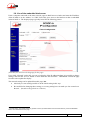
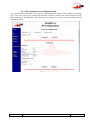
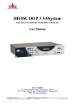
3.6. Use of the embedded html server
From a computer connected to the same network, open an html browser window and enter the IP address
of the SCOOP 4+ in the “address” or “URL” field. This gives access to the html server that is embedded
in the SCOOP 4+. The displayed page typically looks like the following picture:
(Note that you can select the language for this page)
If you click “Network” on the left, you can get a display of the IP addressing data. It is possible to change
settings, and click the “SAVE” button1 to write them into the SCOOP 4+. “REFRESH” reloads the page
from the unit to update the display.
The network settings can be updated from this page, but:
Obviously it is not usually possible to do the initial setting in this way!
Be careful before changing these settings, as a wrong setting here can make you lose control over
the unit… (In such event, go back to 3.5 above)
1 Important notice : each SAVE button only uploads a section (enclosed between two bold horizontal lines), unlike the REFRESH
button, which refreshes the whole page.
26
SCOOP 4+ - User manual
55 000 053 - F
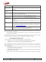
3.6.1. SIP registration and configuration data
You can access these parameters if you click the “SIP configuration” button on the embedded server html
page. This is the only way to configure these settings, and most cannot be set from the keypad (except
those mentioned in the following). The following is an example screen copy, and some comments about
the displayed data:
55 000 053 - F
SCOOP 4+ - User manual
27
Item
Notes
User, Display name, Refer to the network administrator and/or the administrator of the SIP server;
Authentication user Often these three parameters have the same value, as here, but they may be
different.
Authentication
password
Refer to the network administrator and/or the administrator of the SIP server
Registrar
IP address of the SIP registrar; a symbolic name (e.g. sipsrv.mycomp.com) is
accepted, if recognised by the DNS.
Can be also read from the menu (TOOLS / Maintenance / About)
Registration status Shows that the unit is (or is not) successfully registered on the server.
(read only data)
Can be also read from the menu (TOOLS / Maintenance / About)
Outbound proxy
An outbound proxy is one way of getting access through a NAT router or a
firewall;
Refer to the network administrator and/or the administrator of the SIP server
for this setting
STUN server
A STUN server is also one means of getting access through a NAT router.
If such server is available, enter here its IP address or domain name.
Examples of usable STUN servers can be found on the “Support” page of our
web site (http://www.aeta-audio.com))
STUN mode
Enable or disable the use of the STUN server. This allows to keep the address
of the STUN server even when the function is disabled.
This setting is available from the menu (SETUP / Net / Param / STUN Mode)
Make sure to click the “SAVE SIP” button located at the bottom of this section if you want to actually
write your changes into the SCOOP 4+.
For the operation in SIP (unicast) mode, make sure to leave the “Codec mode” setting (top of the
page) on the “SIP” position.
The registration data do not have to be changed often in normal operation. In fact, they may be still valid
even after the unit moves to another location, even though its IP configuration changes.
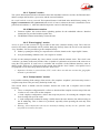
3.6.2. Settings for multicast mode
To use the multicast mode, first select the appropriate mode on top of the page:
« Multicast (send) » if the unit has to be the source of the program to be “multicast”;
« Multicast (receive) » if the unit will be receiving the multicast program.
Some complementary settings may be done for this mode. The default settings can be suitable, but for
network management issues it may be needed to force specific values. To do that, go to the “Multicast”
section of the html page.
« Control port »; this is the UDP port (multicast) used to send the audio stream description. If this
field is left blank, its default value is 6000.
« Audio port »: this is the UDP port (multicast) used for the audio stream itself. If this field is left
blank, its default value is 6001.
« TTL » (Time To Live): leave the default value (128) unless there is a specific reason to change
it.
28
SCOOP 4+ - User manual
55 000 053 - F
3.6.3. “System” section
The system information includes information about the embedded software versions, the Ethernet MAC
address (unique and fixed for a given unit), and the current IP address.
Be careful with the security password. This optional feature is left blank in the initial factory setting. It is
highly recommended to set a password (non-trivial, of course) whenever the unit is installed in a nonprotected environment, i.e. when non authorised persons can access the html page.
3.6.4. Maintenance section
Firmware update: this section allows uploading updates for the embedded software. Detailed
instructions are provided with the update files.
The REBOOT button immediately restarts the unit.
3.6.5. “Event logging” section
Access is given in this section to a log recorded in the codec (internal memory card). The events are
stored in text mode (unformatted ASCII), and the html page directly shows the last 50 events under the
“Log” headline. It is also possible to get the complete history:
Either by opening the full log in a separate tab or window, thanks to the “Open logfile” button;
Or by downloading it thanks to the “Save logfile as” button.
Events are time-stamped (month, day, hour, minute, second) with the internal clock. This clock is not
“real time” (no battery in the unit), but the codec is capable to synchronise at boot time with a time server
using the NTP protocol. If such server is available and accessible via the Ethernet interface, enter its
address in the “NTP server” field on top of this section, then click the “Save” button. A few public servers
are proposed as well in the drop-down list besides “NTP server”.
Important: the date is universal time (UTC), and it does not take into account the geographic
location or possible DST.
3.6.6. “Setup transfer” section
It is possible to backup all the settings of the unit in a file (complete “snapshot”), and conversely restore a
complete setup from a file previously backed up in this way.
This section allows to handle such file transfers between the codec and a computer used for html
browsing:
« Save a complete configuration file » allows to download the complete current setup of the unit
in order to save it into a file on the computer.
« Load complete configuration » allows the reciprocal process, for restoring the complete setup
from a backup file up to the codec.
« Load configuration without IP settings » fulfils almost the same function, but without acting on
the IP addressing. This is often to be preferred, especially when operating the unit only from
remote via IP.
Warning : files transferred in this way are devised for backup, but they are not “portable” from
one firmware version to the other.
55 000 053 - F
SCOOP 4+ - User manual
29
3.7. First level maintenance
3.7.1. Internal description
To be added later
3.7.2. Internal configuration
All the configuration is done in the factory, and/or it can be changed by means of the
keyboard/display interface, without having to open the unit.
However, a few settings can be done internally by setting jumpers:
It is possible to prevent one alarm type to light on the red alarm LED on the back of the
equipment.
It is possible to disable the standby mode (in which case the device is always in operation as long
as the mains power is present).
Please consult us for such operation! We remind that unduly opening the unit can void the warranty. In
any case, opening the unit may expose live parts and is hazardous. Never open or maintain the
internal parts without first disconnecting the AC supply.
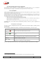
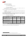
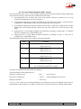
3.7.3. Analysis of malfunctions
The following table indicates the detected alarm conditions and their classification:
Alarm condition
Internal
Power or fuse fault
X
Bad start-up of a microprocessor, or
interface fault detected on start-up
X
External
Overload on an audio input
Minor1
X
Fault on AES/EBU audio input
X
Decoder synchronisation error
X
Network clock fault2
X
Table 3 - List and classification of alarm conditions
Excluding the case when an internal failure disables the management micro-controller, messages are
displayed to indicate the anomaly, or the fault can be searched using the menu.
1 Minor alarms are readable on the display, but do not trigger alarms (contacts and LEDs)
2 Fault of the network clock source currently used for synchronisation (X21/X24 main port or secondary port)
30
SCOOP 4+ - User manual
55 000 053 - F
The test loops accessible from the “TESTS” menu can help improve the analysis of a problem:
In order to check if the audio part functions correctly, use the “Audio” loop and check if the
audio is OK at the output.
To check if the coding part functions correctly, activate “Loop 3” and check if the alarm
disappears (and the decoding indicators come back to normal), and if the audio is present at the
output.
“Loop 2” sends back to the remote codec the compressed data received from the network (see the
description of test loops in 2.4, Supervision and control interface, page 9). This way, it is possible
to test the integrity of the transmitted data and/or check that the remote codec works properly.
The decoder out to encoder in loop (“Audio feedback” loop) can be used for overall functional check, and
also for aligning the overall chain.
In leased line mode, a clock fault is one typical cause of an external alarm. This can be due to:
complete loss of the X24/V11 interface, due to a failure of the transmission line;
a failure of the transmission device connected to the codec;
an incorrect clock frequency (i.e. incompatible with the codec configuration).
On the other hand, in case of a decoder alarm with no clock error, possible causes are :
lack of signal received from the X24/V11 interface, due to a failure of the transmission device
connected to the codec, or a transmission failure in the network ;
a fault in the remote codec, or else the remote codec has an incompatible configuration ;
transmission errors causing erratic alarms.
Errors such as “AES error” and “AES sync loss” can frequently be seen, even when the unit is configured
to use the analog inputs. This is because the AES output is always active, and by default “genlocked” to
the AES input. To avoid such undesired alarms:
When not using digital audio interfaces, set the digital audio sync in “Master” mode
(SETUP / Audio / Digital / Synchro / Master)
55 000 053 - F
SCOOP 4+ - User manual
31
4. Detailed operating mode – User interface
In local mode, the unit is operated thanks to a keyboard and display on the front panel. The display is an
alphanumeric backlit LCD with two 20-character lines.
Operating from the keyboard can be protected by a password (8 digits maximum). In such case, the
password must be entered to start a session and get access to the user menus. The password can be
changed or deleted by the user.
4.1. Main operation modes
There are two parameters which have a major impact on the operation of the unit and on the user
interface.
First, the unit features three transmission modes: transmission over Ethernet/IP, “leased line” mode, and
transmission over the ISDN.
In comparison with the permanent leased line connection, IP and ISDN modes are “dial up” modes and
bring a number of additional parameters to be controlled:
dial number and/or full SIP URI for the destination of a call;
call set up and control;
device SIP registration data, or local ISDN number and sub-address;
miscellaneous network operation parameters.
The status display is slightly different in order to recall the transmission mode currently in use.
Second, in the leased line mode or ISDN mode the unit can be operated either as a normal “single codec”,
or as a “dual codec” capable to transmit two independent 7 kHz bandwidth audio channels. This aspect
has a big influence on the way the device is installed, set up and monitored.
In the following, the main operation modes are shortly designated as: “IP mode”, “ISDN mode” or “LL
mode” (for leased line mode), and “Single codec” or “Dual codec”.
4.2. Equipment start-up
During start-up, the unit displays temporary messages. This initialisation lasts around one minute. Then
the main menu is displayed.
At this stage, if the configuration includes a non-blank password, the keypad is locked and the password
must be entered in order to access the menus: just enter the password (1 to 8 numbers), and the unit is
unlocked as soon as the last digit is entered. On factory setting or after erasure of the unit memory, the
password is blank so this step is skipped.
32
SCOOP 4+ - User manual
55 000 053 - F
4.3. Description of the keyboard
The LED indicators and the main function keys are described in 3.2.1 (Front panel, LCD and basic
control keypad). In its middle section, the front panel includes an alphanumeric keypad used for entering
numbers and/or texts. This keypad is used in a similar way to a mobile phone:
The keypad works in “numeric” only mode, or in “alphanumeric” mode (where both numbers and
letters can be entered).
In numeric mode, only the numbers are used, and the “*” key (as a separation between ISDN
address and sub-address).
The “alphanumeric” mode is the default mode, automatically active whenever this makes sense
(not for dialling an ISDN number). A letter can be entered by pressing repeatedly a key; for
example, a “B” is entered by hitting the “2” key three times (sequence 2, A, B). Use the “vertical
arrow” (same key as the # sign) in order to switch between capital and lower case letters. The “1”
key is used for various symbols which are not all marked on the keypad: « @ », « : », « - »,
« _ »…
For dialling in IP mode, it is possible to force the numeric mode (instead of the default
alphanumeric mode). First press the “*” key; the “>” prompt will appear, and then only numbers
can be entered.
4.4. Description of the menus
The unit features a tree-structured menu, and the three function keys on the bottom of the LCD are used
to navigate through the menus. The OK key is used to confirm some settings or enter data, and the “Esc”
key allows to go back to the upper menu level. Pressing this key several times makes sure you come back
to the main default menu.
From the top menu, you can directly enter one of the three main menus by hitting the function key just
beyond:
TOOLS:
DIR:
SETUP
maintenance and housekeeping functions, and access to status information
access to the directory
configuration of the codec
The “TOOLS” menu is itself divided into three sub-menus:
Status
Maintenance
Misc
information about the status and alarms
test and maintenance functions
miscellaneous functions and settings
The “SETUP” menu is also divided into three sub-menus:
Net
Audio
Cod
selection and configuration of network interface and parameters
configuration of audio interfaces and parameters
selection and configuration of the coding algorithm
The following diagrams show the various sub-menus and accessible parameters.
Note that the “*” character in these diagrams shows the default and/or factory reset value for a given
parameter.
55 000 053 - F
SCOOP 4+ - User manual
33
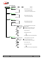
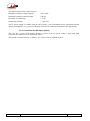
4.4.1. TOOLS/About and TOOLS/Maintenance sub-menus
TOOLS
Notes
Status
<Alarm 1>
…
<Alarm n>
Maintenance
About
IP ADDRESS
VERSION
EIM
SOFTWARE NS
SIP REGISTRAR
REGISTRAR STATUS
displays IP address
displays version info
displays version info
displays "software" serial number
displays SIP registrar's address, if any
displays status (OK or NOK)
Ethernet Setup
DHCP
Manual
IP Address
Mask
Gateway
DNS
switch Full Reduced mode
User Access
Confirm
Password
blank after "factory reset"
Enter new password
Confirm password
Tests
No test loop
Audio loop
Loop3-codec
Loop2-Network
Audio Feedback
34
SCOOP 4+ - User manual
*
55 000 053 - F
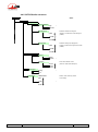
4.4.2. TOOLS/Misc sub-menu
Notes
TOOLS
Miscellaneous
General Reset
CLEAR ALL SETTINGS ?
Yes
No
Antenna Control
Off
On
*
Aux. Functions
only proposed in the spec ific
"Inmarsat BGAN" vers ion
availability depends on the current network and coding algorithm
DATA CHANNEL
Off
On
RELAYS
Off
On
COORD. CHANNEL
Off
On
*
*
*
LCD Backlight
Off
On
*
LED Brightness
Low
Medium
High
*
Language
ENGLISH
FRENCH
…
*
Auto Redial
Auto Redial Cod1
Off
On
Auto Redial Cod2
Off
On
Redial Attempts
1
..
20
Infinite
Time before dial
1
..
30
not relevant for LL mode! (but makes sense for a backup connection)
activates or not automatic redialling in case the c onnection is lost on codec 1
*
activates or not automatic redialling in case the c onnection is lost on codec 2
*
*
use with caution in ISDN mode!
time to wait before a redial attempt
*
Loop Control
Off
On
Backup
*
5A System
A pulse on the control loop releases a running ISDN or IP connection
Outgoing calls are controlled by the control loop state (not relevant for LL mode!)
Use control loop to trigger backup call (for LL mode bac kup)
Concerns ISDN mode only!
Off
On
*
LL Backup
Backup Call
Selection of network for LL backup c all
IP
ISDN
Backup Receive
Off
On
55 000 053 - F
*
Allows the unit to accept an inc oming ISDN or IP call
*
SCOOP 4+ - User manual
35
4.4.3. DIR menu
DIR
Notes
Load/Call
[Profile 1]
Select profile (scroll), then
OK: load selected profile
Green phone: load profile and call
[Profile n]
Delete
[Profile 1]
Select profile (scroll), then
OK: erase selected profile
[Profile n]
Edit
[Profile 1]
Select profile (scroll), then
OK: edit selected profile
(OK)
[Profile n]
ASSOCIATED COD
No change
Current
None
Name
>_
Number1
>_
Edit coding algorithm for this profile
Keep existing
Replace for current setting of unit
No defined coding for this profile
Edit profile name
Edit (first) dial number
Number4
>_
Edit 4th dial number (if existing/needed)
New
ASSOCIATED COD
Current
None
Name
>_
Number1
>_
Coding algorithm for this profile
Use current setting of unit
No defined coding for this profile
Enter profile name
Enter (first) dial number
Number4
>_
36
Enter 4th dial number (if existing/needed)
SCOOP 4+ - User manual
55 000 053 - F
4.4.4. SETUP/Network sub-menu
SETUP
Notes
Net
Other [to select other network]
Param
[for Leased Line mode]
Interface
LL1
LL2
Selection of the active port in normal mode
*
Main port, labelled "X24/V11/V35"
Secondary port, labelled "ALARM + X24/V11"
*
Normal single codec mode
Mode
Normal
DualCodec
Param
[for IP transmission mode]
Network Setup
DHCP
Manual
Select double G722 codec mode
*
IP Address
Mask
Gateway
DNS
Network Quality
LOW
MIDDLE
HIGH
Selection of the preferred
stability / latency compromise
*
STUN Mode
Activate/disable use of STUN
OFF
ON
*
Off
Send
Rcv
*
Multicast
Param
(see "Setting up a link in IP mode")
Activate/disable Multicast mode
Multicast active, stream "sender" mode
Multicast active, stream "receiver" mode
[for ISDN]
Protocol
Selection of local ISDN protocol
,,,
Euro ISDN
,,,
*
Address
Configuration of local line
Local Number 1
Sub-Address 1
(see "Setting up a link in ISDN mode")
Mode
Normal
DualCodec
55 000 053 - F
*
SCOOP 4+ - User manual
Normal single codec mode
Select double G711/G722 codec mode
37
4.4.5. SETUP/Audio sub-menu
SETUP
Notes
Audio
Analog
Input Impedance
High
600 Ohm
*
Max Output lvl
0 dBu
…
+16 dBu
…
+22 dBu
Defines the maximum analog level
reached for a maximum level decoded signal
(0 dBFS )
*
Max Input lvl
0 dBu
…
+16 dBu
…
+22 dBu
Defines the analog input clipping level,
sending a maximum level signal to the encoder
(0 dBFS )
*
Digital
Synchro
Master
Genlock
*
Sampling
Note: valid for "Master" mode
32 kHz
48 kHz
96 kHz
("Genlock" mode follows AES input)
*
Input Source
Analog
AES
Level Meter
38
/HEADROOM
0 dB
…
12 dB
…
40 dB
SCOOP 4+ - User manual
*
Refer to "Audio monitoring" section
for this setting
*
55 000 053 - F
4.4.6. SETUP/Cod sub-menu
SETUP
Notes
Cod
[Previous 1]
[Previous 2]
[Previous 3]
[Previous 4]
[Previous 5]
Other
G711
Not available in LL mode
G722
SRT
H242
H221
CELP
H242: only for ISDN mode
Only for IP mode
4SB ADPCM
MONO
STEREO
L2 J52
Only for ISDN mode,
CHANNEL MODE
MONO
DUAL MONO
STEREO
JOINT STEREO
SAMPLING RATE
16 kHz
24 kHz
32 kHz
48 kHz
BIT RATE
64 kb/s
128 kb/s
192 kb/s
256 kb/s
384 kb/s
ERROR CORRECTION
MODE 0
MODE 1
MODE 2
MODE 3
MPEG L2 with J52
[same parameters as L2 J52]
,,,
but max 128 kb/s in ISDN mode
MPEG L2
AAC-LC / HE-AAC / HE-AAC v2
OPTIONAL, IP and ISDN modes
CHANNEL MODE
MONO
STEREO
SAMPLING RATE
48 kHz
32 kHz
BIT RATE
64 kb/s
128 kb/s
TDAC
OPTIONAL
Important notice: limitations in bit rate depend on the transmission mode, the equipment version
and the software version. This is especially true for MPEG coding.
55 000 053 - F
SCOOP 4+ - User manual
39
4.5. Handling the configuration profiles
The configuration profiles make it easier to change the configuration or set up routine calls. Each memory
or “profile” includes the following fields:
Name allocated to the profile
Number(s): ISDN dial number, or SIP URI, or IP address, depending on transmission mode
Associated coding
A profile may not include a number; in such case it is used for quick and safe recall of a given coding
configuration.
Conversely a profile may not include an associated coding configuration; in such case it is just like a
directory entry, used for instant dialling a known destination.
The configuration profiles are managed and used via the “DIR” menu (see 4.4.3); which provides the
following choice:
Load/Call: after browsing the ordered list (vertical arrows), the selected item can be called
directly by pressing the dial key ; otherwise, on pressing “OK” the coding configuration is
loaded without launching a call.
by typing a letter you can directly reach this letter in the profile list
the horizontal arrow allows you to look the profile parameters (name, number, coding)
Delete: of course this is for erasing a profile, after browsing the list. Press OK when the profile is
selected in order to delete it.
This deletion cannot be cancelled!
Edit: after browsing and selecting the profile, it is possible to selectively edit its fields. Press OK
to select the profile; then for each field, make desired changes, press OK, until all fields have
been edited. The profile is then changed definitively.
New: creation of a new profile. It is possible to enter or not a number, depending on the intended
use for the profile. For coding, the choice left is either not to include it in the profile, or to use the
current one. Of course this means the desired coding must have been configured (using the
CONFIG / Cod menu) before creating the new profile.
The Profile Manager software eases the management of the profiles. Running under Windows, it allows
more user-friendly editing of the profiles on a computer. The available features are the following:
“Off line” profile editing on the computer thanks to the software;
Loading the complete profile set from the computer to a Scoop4+, via an IP link (provided that
the Scoop4+ is connected to the same LAN as the computer);
Reading the profile set of a Scoop4+ into the computer, still via IP;
Backing up the profile set into a file on the computer, for later use, e.g. for “copying” to another
codec.
One can e.g., starting with a Scoop4+ with profiles created using the device menu, read these profiles into
Profile Manager, edit them and create additional ones, then load this updated profile set into the Scoop4+.
However, this is just one example among many ways of using Profile Manager.
40
SCOOP 4+ - User manual
55 000 053 - F
4.6. Setting up a link in ISDN mode
4.6.1. Preliminary setup
The network interface must be configured depending on the local ISDN line that is used.
Protocol
First, the protocol should be set appropriately (SETUP / Net / Param / Protocol). The default setting is
“Euro ISDN”, also known as ETSI protocol. Change this setting if another protocol is needed in your
location.
Local address
In some cases, it may be necessary to set the local address (or local ISDN number) of the line, and/or it is
possible to assign a sub-address to the codec.
The local number allows “multiple subscriber numbering” or MSN. This number is usually the number
remote equipment must dial to call your equipment. Configuring this number in the equipment is not
mandatory if the equipment is directly connected to the public network. On the other hand, if the
equipment is connected to a PABX, the number(s) are often required. The PABX may also impose a
unique number for each B channel within the same BRI interface. In such a case, refer to the
characteristics and configuration of the PABX.
Proper configuration of the local numbers is essential, and many problems in setting up links
originate from mistakes or misunderstandings regarding this configuration. In doubt, leave this
number blank! This is usually appropriate for public lines.
Sub-address SA
This number differentiates several terminals connected to the same ISDN bus, which are allocated the
same call number(s). Thus it can be useful in case other devices are connected with the Scoop 4+ on the
same line.
Whenever a sub-address is set, the unit will only accept incoming calls specifically directed to this subaddress.
Most often, the best setting is to leave this blank!
4.6.2. Call an ISDN number
To set the link, first set –if not already done- the unit in ISDN mode (menu SETUP / Net / ISDN). Then
select the desired encoding format (SETUP / Cod).
You can get a fast setting by simply selecting one of the “recently used” configurations displayed.
Then enter the ISDN number of the destination and press the “green phone” button.
If a sub-address is needed, after the number enter the “*” character and the sub-address (4 digits max.).
The number then has the form nnnn*ssss, e.g. 0912345678*32.
When the selected encoder needs two or more B channels, the unit asks for additional numbers. If the
same number is suitable, just press the “green phone” button without re-entering a number.
An error code is displayed in case of a failure of the link establishment. Refer to annex 6.4 (ISDN error
causes) to find the corresponding meaning.
55 000 053 - F
SCOOP 4+ - User manual
41
4.6.3. Receiving calls
When the 5A System is active, receiving calls is simple. When a call is received, the codec automatically
“unhooks” and recognises the coding algorithm and protocol used, and finally set the link automatically.
On the receiving side, the unit will “follow” the calling unit.
When the 5A System is not active, you should first configure the codec for the desired coding algorithm
and configuration. When a call is received, the unit will synchronise with the calling device, but the link
will usually fail if the calling party has used another coding configuration than expected. However, if J52
is used by both parties, the link will succeed even without 5AS active.
Important notice : the unit can receive and accept incoming ISDN calls even when it is set in IP
mode. On the other hand, it will ignore such calls if it is running in LL mode, except if
the”Backup receive” mode is active (for details see below 4.10, Setting up a backup link).
4.6.4. Quick redialling
Once a number (or a couple of numbers) has been called, it is easy to recall it without having to type it
again: press the “green phone” key, then you can scroll through the “history” (last dialled numbers) using
the arrows. Press the phone key when the desired number is displayed. This is especially useful for
quickly redialling the previous number.
42
SCOOP 4+ - User manual
55 000 053 - F
4.7. Setting up a link in IP mode
A link is set up in a similar way as an ISDN link. The difference is mainly that instead of the telephone
number, we use either an IP address, or a SIP URI (Uniform Resource Identifier).
4.7.1. Directly call an IP address
This is the most basic way of setting the link. It is suitable only if:
The other unit is “directly” reachable, i.e. there is no NAT Router or firewall blocking the
connectivity. The simplest case is when both units are on the same LAN.
The IP address of the other unit is known.
To set the link, first set the unit in IP mode (menu SETUP / Net / IP), and set the desired encoding format
(SETUP / Cod).
Note that you can get a fast setting by simply selecting one of the “recently used” configurations
displayed.
Then enter the IP address and press the “green phone” button.
When operating in this way, it is preferable to leave blank the SIP registering data.
4.7.2. Calling via a SIP server
This is the technique when both units are registered on a SIP proxy server. In this case, each unit is
identified by its SIP URI, in the form username@sipservername, like an email address. There is no need
to know any IP address (and hence there is no problem if the IP address of a unit changes for whatever
reason).
To set the link, first set the unit in IP mode (menu SETUP / Net / IP), and set the desired encoding format
(embedded server, or simply from the keypad SETUP / Cod).
Then enter the SIP URI of the unit to call, and press the “green phone” button.
It is often possible to dial the short form username (omitting the @sipservername) when the
device is itself registered onto the same “sipservername” server.
4.7.3. Receiving calls
This is very simple, in both cases (direct peer to peer link or SIP server). There is nothing to do…
When a call is received, the units negotiate automatically a commonly acceptable coding algorithm, and
set the link automatically. On the receiving side, the unit will “follow” the calling unit.
Important notice : the unit can receive and accept incoming IP calls even when it is set in ISDN
mode. On the other hand, it will ignore such calls if it is running in LL mode, except if
the”Backup receive” mode is active (for details see below 4.10, Setting up a backup link).
55 000 053 - F
SCOOP 4+ - User manual
43
4.7.4. “Network quality” setting
Depending on the quality of service provided on the network, especially its jitter performance, it is
possible to change the stability/latency compromise used by the Scoop 4+. For this purpose, a setting is
available in the menu (SETUP / Network / Param / Network Quality). Three choices are proposed:
“HIGH”:
suitable for a good quality and low jitter network; latency is minimal, but the
codec will have little tolerance to possible jitter
“MIDDLE”:
intermediate (and default) setting, suitable for a moderate transmission jitter
“LOW”:
to be preferred when the network has low QoS, especially for residential ADSL
lines. This setting ensures a safer operation, at the cost of a high latency.
On a LAN and/or private network with a controlled quality, the “HIGH” quality setting is recommended,
as it yields minimum latency.
On the contrary, it should be avoided for a link via the Internet, as it can only tolerate a low jitter. One
solution can be to start with a “MIDDLE” setting, and switch to the “LOW” setting if too much audio
disturbance is heard.
4.7.5. Links with IP phones
SCOOP 4+ is compatible with IP phones that use the SIP protocol (many on the market do). The
algorithm used in this case is G711, but a few IP phones can also accept G722.
Note that “IP phones” include software SIP phones implemented on computers.
4.7.6. Notes about the keypad
Use the “up arrow” key to switch between low case and capital letters.
Once a number or SIP URI has been called, it is easy to recall it without having to type it again:
press the “green phone” key, then you can scroll through the “history” (last dialled numbers)
using the arrows. Press the phone key when the desired number is displayed. This is especially
useful for quickly redialling the previous number or URI.
4.7.7. Multicast mode transmission
On a network that can support it1, the multicast can optimise the resource usage when an audio stream has
to be distributed simultaneously to several destinations. Contrary to the normal bidirectional unicast
mode, this mode is unidirectional: one sender encoder sends a stream towards a multicast group address,
and one or several decoders receiving the stream pick up the packets sent to this group address and
decode the audio stream.
On the Scoop 4+ the operating mode stays quite similar to the “normal” mode, with mainly two
differences in the multicast mode:
A codec must be set as sender or receiver device
SIP is not used and hence the SIP configuration is not relevant
For the operation it is assumed the network “statically” supports UDP multicast, i.e. routers of the
network recognise and deal with routing the packets with multicast group addresses.
1 This does not include the Internet; multicast cannot be used over the Internet.
44
SCOOP 4+ - User manual
55 000 053 - F
For obvious reasons the coding setup is entirely decided at the source. On the codec on the audio source
side (hence sender of the encoded stream), the procedure for setting up a multicast stream is the
following:
Set the codec in “multicast send” mode;
Select on this codec the desired audio coding parameters;
Start the streaming as for setting up a call in normal mode: enter the IP group address, then press
the
key.
Note that the codec decodes its own stream on its audio output; this can be useful for audio
monitoring.
For each codec that has to decode the stream, the procedure is simple:
Set the codec in “multicast receive” mode;
Start the decoder as for setting up a cormal call: enter the IP group address, then press the
key.
55 000 053 - F
SCOOP 4+ - User manual
45
4.8. Auto-redial feature
In LL mode, the unit is always supposed to be linked, and it will transmit and look for a reception signal
as long as it is on. In contrast, the IP mode and the ISDN modes are “dial up modes”, where a link can be
set up and released at will. When it is necessary to hold the link on permanently, outgoing calls may be
backed up by using the auto-redial function. When it is active, the codec can redial automatically in case a
connection fails. The redial capability applies in three situations:
If the initial call fails for any reason (e.g. called party is busy); the codec then redials and retries
to establish the link.
The codec can also redial if the link is already established and the link is lost, for any reason else
than “local release” (e.g. the remote unit mistakenly dropped the line).
After a power failure, after rebooting the codec will automatically redial and set-up the link back.
Note that, while “auto redial” is active, an established link can be definitively stopped only by
releasing the line on the calling codec side.
It is possible to program the time period that the unit will wait before redialling after a failed trial, and it
is also possible to program the maximum number of times the codec will redial before giving up.
The activation of this function and the configuration of its parameters can be found in the “Auto Redial”
sub-menu (TOOLS / Misc / Auto Redial menu). In dual codec mode, the function can be activated
separately for each codec.
4.9. Loop control
In normal operation for IP or ISDN mode, outgoing calls are sent or released using the menus and/or the
remote control interface. When the loop control function is selected, outgoing calls are controlled by
activating or not optically isolated input loops. One loop is available for each codec when in double codec
mode. When the input loop is activated (i.e. current is flowing), the corresponding codec establishes a
link by calling the last number (or SIP URI in the IP mode) previously dialled by the unit. When the loop
is de-activated, the codec releases the line and stays idle as long as the loop is not active (except if
receiving an incoming call).
In normal operation, it is nevertheless possible to release a running connection by briefly
activating (“pulse”) the control loop.
The “auto-redial” feature is implicitly active when loop control is active: the codec tries to keep the link,
and automatically recalls the remote unit if the line drops, as long as the input loop is active. The “time
before redial” parameter described in the above is also applicable to the loop control mode. On the other
hand, the “redial attempts” parameter is not applicable here, because the unit will always try to recover
the link, until the loop is left inactive.
Note that, as an important consequence, when using loop control, the termination of a link must
always be done on the calling party side by de-activating the input loop. Whenever the line is
released by the receiving party, the calling unit will redial and re-establish the link.
When loop control is active, the input loops are the only means of setting up an outgoing call; setting a
call from the menu is not allowed.
Remind that the first step is to set-up the link once in normal mode, and later activate the loop
control mode; afterwards the input loop is used to trigger a redial to the previous ISDN number
or SIP URI.
46
SCOOP 4+ - User manual
55 000 053 - F
4.10. Setting up a backup link
The SCOOP 4+ has the capability for backing up a permanent leased line audio link thanks to an ISDN
connection, or an IP connection.
A typical example of this application is shown in the following diagram, where a permanent leased line is
used for transmitting a radio programme from a studio to a transmitter. A codec is installed on each side
of the link, and each codec is also connected to the ISDN or an IP network. In this way, transmission via
the ISDN (or respectively IP) can be used as a temporary back-up in case the normal permanent link fails.
Once the problem on the normal line is solved, the connection on ISDN (resp. IP) can be released and
normal operation in LL mode is restored.
ISDN or IP network
Back-up connection
Studio
Audio
Transmitter
Leased line
CODEC
CODEC
The SCOOP 4+ makes such back-up easy because both transmission interfaces (normal leased line and
backup interface, ISDN or IP) are available in the same unit. Moreover, the SCOOP 4+ helps to automate
the switchover process, especially on the transmitter side, where most often quick human intervention is
not possible. The following describes one way of configuring such a system, and details the resulting
backup process.
4.10.1. Basic principles
When a failure of the leased line is detected, one of the two codecs has to switch to ISDN (resp. IP)
“backup” mode, and then call the other unit over the backup network access. The audio transmission in
then provided over the backup link. Later on, when the leased line comes back to normal, the backup
connection can be released and both codecs have to switch back to LL mode and normal operation.
We designate as “caller” the codec which switches first and initiates the call over the backup network,
and “receiver” the codec which switches on receiving such a backup call.
4.10.2. Caller codec: setup and operation
For the switch to backup (following a failure on the leased line), two methods can be used:
Either the switchover is “manual”: an operator on the studio side can switch the studio codec to
ISDN (IP) mode and launch a call to the other site via the backup medium. For this method, no
special preliminary setting is needed.
The other method is to use the “loop control” feature as described above in section 4.9. In this
case, the whole switchover sequence can be executed by simply activating the input loop.
Conversely, releasing the input loop brings the unit back to normal operation in LL mode.
For this latter method, the best situation is when the leased line status is monitored by an alarm contact
that closes when the line is down. This alarm can be used for activating the control loop, so that the studio
codec quickly and automatically switches over to backup mode (and also comes back to normal when the
leased line recovers); no manual intervention is needed in such case.
55 000 053 - F
SCOOP 4+ - User manual
47
In order to use this operating mode, two settings have to be done on the “caller” codec:
Select the network to use for backup: menu TOOLS / Miscellaneous / LL Backup / Backup
Call…
Activate the loop controlled backup: menu TOOLS / Miscellaneous / Loop Control / Backup
Important notice: when switching to backup mode the number called is the last dialled! For this
reason it is important to dial and call the backup destination in the desired mode at least once,
before setting the unit in its normal LL mode.
4.10.3. Receiver codec: setup and operation
The setup is easy on the “receive” side of the backup link, as it is somewhat “passive”. The “backup
receive” mode must be activated, via the menu TOOLS / Miscellaneous / LL Backup / Backup Receive.
Once this is done, when the codec is operating in LL mode, on receiving a call from the ISDN interface or
the IP interface, the codec switches to the ISDN or IP mode, answers the call and the connection is
established with the remote codec. Later, when the temporary connection is released (by the calling
party), the “receiver” codec automatically switches back to LL mode, and normal operation is resumed.
Reminder: in LL mode the codec accepts no incoming call from its IP or ISDN interfaces, unless
the backup receive mode is active.
Conversely, once this is done, the codec accepts incoming calls regardless of the network
interface, IP or ISDN.
Thanks to the automatic coding algorithm detection (5AS in ISDN mode or SIP/SDP in IP mode),
the coding setup is not critical on this “receiver” side. However, for increased safety in ISDN
mode one may prefer to force the configuration (by de-activating the 5AS).
4.10.4. Notes regarding the automatic switchover
Note that, when switching from LL to ISDN or IP mode, a separate set of parameters is recalled. As a
consequence, the coding configuration can be made, if desired, totally different in the back-up ISDN or IP
mode.
Of course, both units should be configured in an adequate configuration for each transmission mode, and
then each codec can be set in the LL mode to start the normal operation.
For the ISDN (and backup) configuration, DO NOT set the units in double codec mode.
Otherwise, the automatic switchover will not work properly.
48
SCOOP 4+ - User manual
55 000 053 - F
4.11. Erasing and resetting the configuration
In some cases like e.g. if the password is forgotten, it may be necessary to restart from the factory default
setting.
To erase the entire configuration and load the factory default settings, you should normally go to the
“General Reset” sub-menu (TOOLS / Misc / General Reset).
In case the keyboard is locked and you have lost the password, hold the “hang up” key pressed
for 10 seconds; this forces the system directly to the “General reset” sub-menu. You can then
confirm that you really want to erase all the settings, including the password…
The factory default password is blank.
4.12. Backing up and recalling the configuration
It is possible to backup all the settings of the unit in a file (complete “snapshot”), and conversely restore a
complete setup from a file previously backed up in this way. Such transfers are done using the embedded
html server; refer above to 3.6.6 for the operation.
55 000 053 - F
SCOOP 4+ - User manual
49
5. Technical characteristics
5.1. Characteristics of interfaces
5.1.1. Analogue audio inputs
Audio characteristics are measured over a 20 to 20 000 Hz bandwidth except when differently stated.
The inputs are balanced type, using 3-pin female XLR sockets.
Maximum input level:
adjustable from 0 to +22 dBm ± 0.3 dB
Nominal input impedance:
600 or 10 k (menu setting,
SETUP / Audio / Analog / Input Impedance)
Impedance balance:
TBD
Common mode rejection ratio:
> TBD dB
(measured with Z = 600 )
5.1.2. Analogue audio outputs
Audio characteristics are measured over a 20 to 20 000 Hz bandwidth except when differently stated. The
outputs are balanced type, using 3-pin male XLR sockets.
Maximum output level:
adjustable from 0 to +22 dBm ± 0.3 dB.
Nominal load impedance:
600 or 10 k
Output impedance:
<50
Symmetry:
> TBD dB
(ZL = 150 )
5.1.3. Digital audio input and output
These interfaces comply with recommendations:
AES3-1992
EBU Tech. 3250-E
CCIR Rec. 647
They support (in genlock mode) a sampling rate from 28 to 96 kHz. In master mode, the unit can be set in
one the following sampling rates: 32, 48 and 96 kHz.
5.1.4. Headphone output (front panel)
This output (6.35 mm jack on front panel) is for the connection of a 32 headphone. It is also possible to
plug a high impedance headphone; however, the maximum available power will be lower.
50
SCOOP 4+ - User manual
55 000 053 - F
5.1.5. Main X24/X21/V11/V35 interface
The X24/V11 interface uses a 15-pin male Sub-D connector. The following table shows the pinout.
Signal
Frame ground
Transmitted data
Pin
Ta
Received data
Indication
Received clock
Ra
Ia
Sa
Electrical ground
1
2
3
4
5
6
7
8
Signal
9
10
11
12
13
14
15
Tb
Transmitted data
Rb
Ib
Sb
Received data
Indication
Received clock
The codec does not transmit a C signal.
The codec can also be connected to V35 interfaces; a specific adaptation cable is needed in such case. The
connection is described in Annex 6.5, (V35 interface adaptation).
5.1.6. “Alarm + X24/X21” interface
This interface uses a 15-pin male Sub-D connector. The following table shows the pinout.
Signal
Internal alarm - Common
Transmitted data
Internal alarm - NC
Received data
Indication
Received clock
External alarm - NO
Electrical ground
Pin
IA-Com
Ta
IA-C
Ra
Ia
Sa
EA-O
1
2
3
4
5
6
7
8
Signal
9
10
11
12
13
14
15
Tb
IA-O
Rb
Ib
Sb
EA-C
EA-Com
Transmitted data
Internal alarm - NO
Received data
Indication
Received clock
External alarm - NC
External alarm - Common
The bold text refers to the alarm contacts. Both are form-C type. The “NO” terminal is open when the
alarm is set, otherwise it is connected to the “Common” terminal. The “NC” terminal is connected to the
“Common” terminal when the alarm is set, otherwise it is open.
The current and voltage handling capabilities of the relays (static type) are:
Maximum output current:
120 mA
Maximum output voltage:
350 V peak
Resistance of output loop:
< 35
Isolation
> 1500 VRMS
The codec does not transmit a C signal.
The codec can also be connected to V35 interfaces; a specific adaptation cable is needed in such case. The
connection is described in Annex 6.5, (V35 interface adaptation).
55 000 053 - F
SCOOP 4+ - User manual
51
5.1.7. Remote control interface
This interface uses a 9-pin female Sub-D connector on the rear panel. This is a V24/RS-232 type interface
with only Tx and Rx signals (no flow control). The following table indicates its pinout (DCE type
pinout).
Pin
Function
2
Rx
V24 data to the PC
Output
3
Tx
V24 control data, from the PC
Input
5
Ground
Other
Not connected
The interface is configured as follows: 4800 bauds, 8 bits, no parity, one stop bit.
5.1.8. Data interface (« data »)
This V24 interface uses a 9-pin female Sub-D connector on the rear panel. Like for the remote control
interface, only Tx and Rx are used, there is no flow control, and the pinout is of DCE type.
Pin
Function
2
Rx
Received V24 data
Output
3
Tx
Transmitted V24 data
Input
5
Ground
Other
Not connected
The data interface is configured as follows: 8 bits, no parity, one stop bit. It is possible (see menu TOOLS
/ Misc / Aux. Functions / DATA CHANNEL) to activate the interface and to configure its baud rate (300
to 9600 bauds). However, the maximum allowed baud rate depends on the audio coding used (see 2.6.1 Data channel).
5.1.9. Ethernet interface
This RJ45 socket has standard Ethernet pinout (for use of a normal “straight” cable to an Ethernet hub or
switch).
The installation and operation of this function is detailed in 3.5, Initial setup of the Ethernet interface.
5.1.10. “Digital I/O” interface
TBD
52
SCOOP 4+ - User manual
55 000 053 - F
5.1.11. Relay transmission interface (“AUX” socket)
The relay transmission interface (refer to 2.6.2, Relay transmission) is available on the 25 pin female
sub-D “AUX” Socket. It includes two isolated current loop inputs and two dry contact outputs.
The following table shows the pinout of the socket for this function:
Pin
Function
13
Output loop n°2 (b)
25
Output loop n°2 (a)
12
Output loop n°1 (b)
24
Output loop n°1 (a)
11
Input loop n°1 (b)
23
Input loop n°1 (a)
10
Input loop n°2 (b)
22
9
Input loop n°2 (a)
+5V of internally supplied power supply
21
0V of power supply
All loops are isolated and bi-directional (free polarity).
The characteristics of the input loops are:
Input loop control current:
6 mA
Resistance of input loop: 560
(current limiting series resistor)
Input loop isolation:
> 1500 VRMS
(max. 100 mA)
A +5V to +12V source may be connected directly on an input loop, because the internal series resistor is
dimensioned for this purpose. For a higher voltage source, it may be necessary to limit the input current.
The characteristics of the output loops are:
Maximum switching voltage (output):
350 V peak
Maximum switching current (output):
120 mA
Resistance of output loop:
< 35
Output loop isolation:
> 1500 VRMS
The 5V power supply is available from the unit to power a low-consumption device (maximum 300 mA
current consumption), or e.g. to power the input loops or LED indicators connected to the output loops.
55 000 053 - F
SCOOP 4+ - User manual
53
5.1.12. Coordination channel interface (“AUX” socket)
In addition to the loop control and relay transmission interfaces, the (optional) coordination channel input
and output are available on the 25-pin female sub-D connector (“AUX” Socket on the rear panel), with
pinout as indicated hereunder.
The input and output are balanced floating signals, transformer isolated.
Maximum level:
9 dBm
Impedance:
600
Nominal bandwidth:
300 – 3400 Hz
54
Pin
Function
1
Coordination channel output (-)
14
Coordination channel output (+)
2
Frame ground
15
Coordination channel input (+)
3
Coordination channel input (-)
16
Frame ground
SCOOP 4+ - User manual
55 000 053 - F
5.1.13. Loop control interface (“AUX” socket)
The 25 pin female sub-D “Aux.” socket includes isolated current loop inputs and dry contact outputs, that
can be used to remotely control the calls and indicate the link status:
The input loops have an effect only if the “loop control” function is enabled (see 4.9, Loop
control). The output loops are always operative.
Activating the input loop #1 triggers an ISDN or IP call on the codec (codec 1 only if the unit is
configured as a double ISDN codec); de-activating the loop releases the line.
Activating the input loop #2 triggers an ISDN call on codec 2 if the unit is configured as a double
ISDN codec; de-activating the loop releases the line. This loop has no action in single codec
mode.
Output loop #1 is closed while an ISDN or IP connection is running, or while codec 1 is linked if
the unit is configured as a double ISDN codec ;
Output loop #2 is closed while an ISDN connection is running on codec 2, if the unit is
configured as a double ISDN codec ;
The following table shows the wiring of the socket for this function:
Pin
Function
17
Input loop n°2 (a)
5
Input loop n°2 (b)
18
Input loop n°1 (a)
6
Input loop n°1 (b)
19
Output loop n°2 (a)
7
Output loop n°2 (b)
20
Output loop n°1 (a)
8
Output loop n°1 (b)
21
9
0V of power supply
+5V of internally supplied power supply
All loops are isolated and bi-directional (free polarity).
The characteristics of the input loops are:
Input loop control current:
6 mA
(max. 100 mA)
Resistance of input loop:
560
(current limiting series resistor)
Input loop isolation:
> 1500 VRMS
A +5V to +12V source may be connected directly on an input loop, because the internal series resistor is
dimensioned for this purpose. For a higher voltage source, it may be necessary to limit the input current.
55 000 053 - F
SCOOP 4+ - User manual
55
The characteristics of the output loops are:
Maximum switching voltage (output):
350 V peak
Maximum switching current (output):
120 mA
Resistance of output loop:
< 35
Output loop isolation:
> 1500 VRMS
The 5V power supply is available from the unit to power a low-consumption device (maximum 300 mA
current consumption), or e.g. to power the input loops or LED indicators connected to the output loops.
5.1.14. Connector for DC input (option)
The “12V DC” version of the product includes, in place of the AC power socket, a 4-pin male XLR
socket for the connection of an external DC source.
The ground is connected on pin 1, and the +12V source must be supplied on pin 4.
56
SCOOP 4+ - User manual
55 000 053 - F
5.2. Audio performance
The audio performance in this part applies to the system without coding/decoding, and excluding the
coordination channel. The additional effect of the audio encoding and decoding on audio performance
depends on the coding algorithm used and its parameters.
Except when differently stated, the following measurements are done at a +6 dBm input level and on the
AD/DA path, with maximum input and output level set at +16 dBu.
5.2.1. Transmission gain
The drift in time of the gain from the input to the output of the codec is less than 0.3 dB.
5.2.2. Amplitude-frequency response
All measurements are done with a +6 dBm input signal, and a reference frequency of 1020 Hz. The
measurements are done with a loopback before coding/decoding, so the possible effect of compression
has no influence.
To be detailed
5.2.3. Group delay distortion
Taking the minimum group delay as reference, the group delay distortion on the AD/DA path is always
less than 1 ms.
5.2.4. Idle channel noise
Background noise is measured with no audio modulation (idle channel), with maximum input and output
level set at +16 dBu, through the whole encoder-decoder chain (wide band coding, with 48 or 32 kHz
coding frequency).
Maximum noise level1:
- 56 dBm
(quasi-peak detection, CCIR weighting)
(or - 62 dBq0ps)
This result in a signal to noise ratio (SNR) of more than 72 dB.
When the maximum input and output level is set at another level, both the signal and noise levels are
shifted but the SNR remains in the same range.
5.2.5. Total distortion vs. frequency and level
Total distortion relative to maximum level (or THD + N) is less than –82 dB over the whole audio
bandwidth (20 – 20 000 Hz). This performance holds for audio signals from –80 dB to –1 dB relative to
the maximum level (+16 dBu).
5.2.6. Crosstalk
Crosstalk is less than -80 dB over the whole bandwidth.
5.2.7. Gain and phase difference between channels
The gain difference between channels is less than 0.3 dB over the whole bandwidth, for any sampling
frequency.
The phase difference between channels is less than 3 degrees over the whole bandwidth, for any
sampling frequency.
1 Worst case for all types of algorithms; MPEG performs better than the others
55 000 053 - F
SCOOP 4+ - User manual
57
5.3. Network protocols and ports
The Scoop 4+ implements or complies with the following protocols (non exhaustive list):
Physical and link layers: Ethernet, 100BaseT, 10BaseT
Network/Transport layers (IPv4) : TCP/IP, UDP/IP, RTP/IP
Application : HTTP, Telnet, DHCP, STUN
Audio transmission: SIP signalling, SDP, RTP, RTCP, RFC3550/3551, RFC3640
Compliant with EBU recommendation Tech 3326 (interoperability of audio codecs for
contribution)
The ports used by the device are the following:
Type
Port
Désignation
80 HTTP
TCP
UDP
Notes
Embedded html server
6000 Control
Remote control (« command line »
used by Scoop4Man and TeleScoop
3478 STUN
For querying a STUN server (optional)
5004 RTP
For audio streaming
5005 RTCP
For audio streaming
5060 SIP
SIP signalling
6000 Multicast/description
Multicast stream description channel
6001 Multicast/audio
Multicast stream transmission channel
mode) ;
The ports for multicast mode can be changed from the default values in the above table.
5.4. Power supply
The codec operates from mains 85-263Vac, 47-63 Hz. Protection is provided by a resettable fuse. The
maximum power consumption is 15 W (without the coordination channel option).
A product version is available which is powered from a +12V DC source (non isolated). The unit includes
protection against overcurrent (resettable fuse on the DC input) and overvoltage.
The DC source voltage must be in the 10V-15V range. The maximum consumption is 1 A (for a 12V DC
source).
5.5. Dimensions and weight
The unit is a 19 inches frame of 1U height (44 mm or 1.75”) and 252 mm depth (12.5”).
Its weight is about 3.2 kg.
58
SCOOP 4+ - User manual
55 000 053 - F
5.6. Environmental characteristics
The equipment operates over a 0°C to 45°C ambient temperature range (32°F to 113°F), and a 5% to 90%
humidity ratio range.
The SCOOP 4+ complies with “CE” directives regarding safety and EMC.
Safety: compliance with EN60950
EMI: radiated emissions complying with EN55103-1
Susceptibility: compliance with EN55103-2
5.7. Versions - Options
The various versions available for the SCOOP 4+ are the following:
SCOOP 4+ DUO LL/IP: with Ethernet/IP and leased line interfaces
SCOOP 4+ TRIO LL/IP/ISDN 2B: with Ethernet/IP, leased line interfaces and one ISDN
interface
SCOOP 4+ TRIO LL/IP/ISDN 4B: with Ethernet/IP, leased line interfaces and two ISDN
interfaces
Besides, certain functions are available as options:
MPEG AAC-LC audio coding;
MPEG HE-AAC and HE-AAC v2 audio coding;
Audio coordination channel;
TDAC algorithm for ISDN mode;
12V DC power (instead of AC mains)
5.8. Accessories and related products
The SCOOP 4+ is delivered with a mains cord and a CAT5 Ethernet cable.
Along with the coordination channel option, a specific cable is delivered, which provides XLR plugs for
the coordination channel input and output (input on a female plug, output on a male plug).
For remote controlling SCOOP 4+ units from a PC, the Scoop4Man configuration and supervision
software is available (for a Windows computer).
The TeleScoop supervision software is also available and allows to control the other rackmount codecs
of the Hifiscoop, Scoop 3 and Hifiscoop 3 ranges (please consult us).
55 000 053 - F
SCOOP 4+ - User manual
59
6. Annexes
6.1. Complements on the algorithms and protocols used
6.1.1. Auxiliary data in the MPEG frames
The auxiliary data are used for the following purposes:
Reed-Solomon error detection and correction (J52 standard)
Data channel
Other auxiliary information: relay transmission, and/or auxiliary audio channel.
The insertion of this auxiliary information is an extension (AAS proprietary format) to MPEG.
However, the frame structure remains compliant.
6.1.2. Reed-Solomon encoding
In order to cope with possible transmission errors in the network, Reed-Solomon error correction coding
can be added, compliant with J52 recommendation. Four correction modes are available in the
SCOOP 4+:
Mode 0 : no error correction, Reed-Solomon coding disabled
Mode 1 : protection of only the control information and scale factors in the MPEG frame, low
redundancy (so-called “unequal protection”)
Mode 2 : protection of the whole frame, moderate (2.5 %) redundancy (so-called “low equal
protection”)
Mode 3 : protection of the whole frame, high (10 %) redundancy (so-called “high equal
protection”)
Higher redundancy increases the protection against errors, but slightly degrades the audio quality, as
redundancy takes up part of the bit rate that could be allocated to audio coding.
Most often, for a normal quality transmission link, mode 1 is sufficient and it consumes little bit rate from
the compressed data, so it hardly impacts the audio quality. Although J52 does not apply to leased line
connections, this error protection technique is also implemented in the SCOOP 4+ in leased line mode.
6.1.3. H221 framing
H221 defines a framing structure that allows byte synchronisation recovery in leased lines, and the
transmission of control data along with the main data.
6.1.4. Proprietary coding algorithms
The “proprietary” coding algorithms are algorithms which are not standardised by the ITU-T but have
distinctive features that make them useful for some applications:
Low coding-decoding delay (4SB ADPCM);
Low bit rate wide band speech coding (CELP)
TDAC (Time Domain Aliasing Cancellation, MDCT-based algorithm)
60
SCOOP 4+ - User manual
55 000 053 - F
6.2. Overview of the SIP protocol
6.2.1. What is SIP?
SIP is for Session Initiation Protocol, a protocol specified by the IETF for establishing media
transmission sessions. SIP is considered the communication protocol of the future by most vendors, and
as such it has deep influence on the VoIP applications.
As a signalling protocol, SIP brings methods and techniques to solve the issues related to the establishing
of an audio link. Almost as important, it is a recognised standard, implemented on many network devices
and systems. Using SIP helps you build modular and really evolutive systems, not being tied to a single
vendor.
The SIP protocol is an essential requirement in the EBU Tech 3326 recommendation (a.k.a. “N/ACIP”
recommendation).
6.2.2. Setting a link with SIP
Let us look at an example (diagram below): a reporter on the move with a Scoopy+1 wants to make a call
to a SIP compliant codec located in the main station. The reporter may be at home, or at another location,
not necessarily known in advance.
Once the Scoopy+ is on and connected to the network, it will register itself to a SIP “registrar”. This
registrar can be located on the LAN of the radio house, but it may as well be elsewhere in the network.
Then the registrar “knows” where the Scoopy+ is, what its IP address is. On the radio house side, a
similar process takes place .
To call the codec of the radio house (e.g. a SCOOP 4+), the reporter just needs to know its SIP address,
which can be like [email protected] (indeed very similar to an e-mail address). To call the unit,
the reporter has to select the preferred audio coding mode on the Scoopy+ (e.g. mono G722), then call the
remote unit, simply using this SIP address (SIP URI).
What happens then on the network: the Scoopy+ sends the request (INVITE in SIP protocol) to a
proxy server (often the same device is also the registrar). To make things simple, this proxy then relays
and routes the request to its destination. Resolving the SIP URI to a physical network and address uses
mechanisms similar to those used for resolving URLs. Several proxys may be involved in cascade to
finally reach the desired destination, but this does not have to be known or dealt with by the end devices.
The following is like the initiation of a phone call: the IP codec “rings”; if it accepts the call, this is
notified to the Scoopy+.
At this stage, the proxy(s) provide the Scoopy+ and the IP codec with all the address data they need for
the link, then the actual audio streams can be exchanged between both units. As a very important
feature, the end devices now can exchange data directly; the proxys do not have to be on the path, they
are only involved in the setting (and later the ending!) of the session. The codecs will automatically
exchange their coding capabilities, and agree on a coding mode, with no further user intervention.
Alternatively, the call can be done from the station to the reporter, in a way very similar to the above. In
contrast with ISDN links, the operators at the station do not even need to know where the reporter is
located! This is because the registrar deals with this issue.
Note that it is also possible to set a link with a SIP-compliant VoIP phone instead of another codec. This
is one of the numerous advantages of using a standard.
1 Scoopy+ is a portable audio codec from AETA AUDIO SYSTEMS; the description here applies to both Scoopy+ and the
Scoop 4+, as they are both SIP compliant and mutually compatible
55 000 053 - F
SCOOP 4+ - User manual
61
IP phone
SIP proxy
server
Gateway
4
IP
network
2
1
Gateway
Gateway
SIP
registrar
IP codec
5
62
3
SCOOP 4+ - User manual
Scoopy+
with IP interface
55 000 053 - F
6.3. Some methods to deal with NAT routers and firewalls
Problems arise when the desired connection has to go through a NAT router, and/or a firewall, that blocks
a direct IP communication.
This is a very common issue, especially if one needs to set up a transfer via the Internet. It is impossible
here to describe in details the possible ways to deal with this problem, but the following just shortly
discusses some typical solutions. Most probably, a network administrator should be consulted for support,
and for granting adequate network authorisations and/or privileges.
The most classical issues are related to:
The presence of a NAT router on the network path between the codecs.
The presence of a firewall on this path.
It is always important to have available the information regarding the network organization and to be
allowed to access the devices which need to be configured. Hence we highly recommend to involve the
persons empowered for such tasks.
6.3.1. Links via a private network
No special problem should be met within a LAN. The operation is also possible with codecs from other
manufacturers, provided that they comply with the Tech3326 EBU recommendation (also known as
“N/ACIP” recommendation). However you should check for specific settings or preparation possibly
needed on such devices.
A wide area network covers a wider geographic range, and the network topology most probably includes
routers on the path between the codecs to be linked. However, usually there is not much difference with a
local area network.
Note: using a VPN leads to just the same case; the operation is identical as far as the codecs are
concerned.
6.3.2. Links through a public network (Internet)
If each of the units has got a “direct” access to Internet with a public address, we are in the same situation
as the previous one, functionally speaking (private WAN). The addressing scheme is normally static, as
DHCP can rarely be used on a public access. In fact, this situation is very seldom met in the field!
First, the Internet access is usually protected by a firewall which will, as a principle, block a priori the
desired connection. In such case exceptions (to the firewall security rules) must be created, that will allow
this connection; this has to be done by the person in charge of the network management.
Most often, on one access if not both, the codec accesses the Internet via a NAT router. This router shares
Internet access, with one or a few public addresses, among the equipment on the LAN. On this LAN the
devices get local private addresses, and the router carries out an IP address translation. Note that:
As an example, a consumer ADSL modem-router is almost always a NAT router, sharing a single
public IP address between the devices connected to the router.
It is just the same on a 3G/3G+ mobile IP access ; the terminals (phones or computers) access the
Internet via NAT routing.
NAT routing is often included in the firewall features; in fact NAT routing somewhat participates
to the protection against direct attacks from the outside.
55 000 053 - F
SCOOP 4+ - User manual
63
NAT routing is an obstacle to transmission with UDP, mainly for two reasons:
It does not allow unsolicited data to come in from the outside network. In other words, data input
is accepted on a port as an answer to a request from the local network, but an external agent
cannot directly initiate the transmission of a packet.
The terminal units on the LAN only know their private local address. On the other hand, agents
implementing the SIP protocol have to communicate to each other the addresses and ports to be
used for the media exchanges. Because of the NAT routing, agents do not get the real public
addresses, which leads to failure of the session setup attempts.
We are now looking at various methods used to overcome these obstacles.
NAT and use of the STUN server
The STUN protocol is a method which is often successful1 in helping the agents to discover their public
address even when they are « hidden » behind a NAT router. Here is the operation principle:
A STUN server is used, which is accessible over the Internet ;
The address of this server is programmed into the agent (i.e. the audio codec in our topic);
The agent queries the server and discovers its public IP address and port number, as seen from
outside of the NAT router and LAN;
This addressing information is then used by the agent for negotiating and setting up a media
session.
The STUN server address is programmable in the html page of a Scoop 4+ or Scoopy+. Besides, one can
also find in the menu (keypad and display on the front of the unit) an activate/disable (on/off) selection,
available without having to clear the server address.
The are many public STUN servers available on the Internet; here are a few examples, valid at the time of
writing:
Domain name
Numeric address
stun.xten.com
75.101.138.128
stun.ekiga.net
75.101.138.128
stun.sipgate.net
217.10.79.2
stun.ippi.com
208.73.210.27
stun.sipphone.com
198.65.166.165
Examples of STUN servers
It is advisable to check that the server is operative. A list of servers can also be found on the support page
of our web site http://www.aeta-audio.com.
1 Although not with so called « symmetric » NAT routers
64
SCOOP 4+ - User manual
55 000 053 - F
Standard NAT router
Situation: codec A behind a NAT router with no specific programming (a codec accessing Internet via a
mobile network is almost always in such situation). We also assume that the other codec (B) is accessible
with a public address.
Once codec A is configured for using a STUN server:
codec A can initiate a connection to (call) codec B
codec B cannot call codec A
Advantages
Drawbacks
Configuration is relatively simple
B cannot call A
No change is needed on the router
Several codecs can be set behind the NAT
router
Method suitable for mobile network access
NAT router with DMZ
Situation: codec A behind a NAT router and placed in « DMZ ».
We also assume that the other codec (B) is accessible with a public address.
Once codec A is configured for using a STUN server:
codec A can initiate a connection to (call) codec B
codec B can call codec A, using the public address of the NAT router
Advantages
Drawbacks
Each codec can set up a session
Need to configure the router
A is nearly equivalent to a codec with a Only one codec can be set up in this way on a LAN
direct public access
A is exposed to external attacks
The DMZ may be already reserved for other network
equipment
Method not possible for a mobile network access
NAT router with port forwarding
Situation: codec A behind a NAT router and configuration of the router to forward to A the necessary
ports.
We also assume that the other codec (B) is accessible with a public address.
Port forwarding to be set on the router:
UDP 5060 (=SIP port)
UDP 5004 (RTP port) and 5005 (RTCP port)1
1 For Scoop4+ versions before 1.32, ports 9000 and 9001 respectively
55 000 053 - F
SCOOP 4+ - User manual
65
Once codec A is configured for using a STUN server:
codec A can initiate a connection to (call) codec B
codec B can call codec A, using the public address of the NAT router
Advantages
Drawbacks
Each codec can set up a session
Need to configure the router
A is nearly equivalent to a codec with a direct Only one codec can be set up in this way
public access
on a LAN
Method not possible for a mobile
network access
Use of a SIP server
In addition to the numerous features it brings along, using a SIP proxy server is a very powerful method
to solve the issues related to NAT routers, because most SIP proxies are capable to detect the presence of
NAT routers and/or deal appropriately with their traversal.
If a SIP server is available, and once the codecs are registered on this server:
Any registered codec can call another registered1 codec, regardless whether there is or not a NAT
router on the path.
The identifier (SIP URI) is stable and does not depend on the location of the called agent
(“mobility” feature).
It is possible either to use a public server on the Internet, or to install a private server accessible via the
Internet.
Advantages
Each codec can initiate
Each codec can receive calls
Drawbacks
a
session Installation may not be easy (private
server)
Identification is simple and location/time-wise
stable
Reliability of server questionable (public
server)
Security : a private proxy can be linked with a
firewall
Also works with symmetric NAT routers
Interoperation with telephony over IP
Method suitable for mobile network access
1 Depending on the access control policy, a server may accept « outgoing » calls to third party domains, or accept « incoming »
calls from non registered agents.
66
SCOOP 4+ - User manual
55 000 053 - F
6.3.3. Summary and reminder of essential rules
The table below sums up the situations where a link can be set up (not using a SIP proxy server) and
reminds the needed specific settings :
Codec A
access
Possible
calls
Codec B
access
Notes
1
LAN
LAN
(same)
2
Private WAN
Private WAN
3
Internet direct
Internet direct
4
NAT
Internet direct
STUN needed for A
5
NAT + DMZ
Internet direct
STUN needed for A
6
NAT + port
forwarding
Internet direct
STUN needed for A
UDP ports 5004, 5005, 5060
7
NAT
STUN needed for A and B
8
NAT + DMZ
NAT + DMZ
NAT + DMZ
9
NAT + port
forwarding
NAT + DMZ
STUN needed for A and B
UDP ports 5004, 5005, 5060
10
NAT
NAT + forwarding
STUN needed for A and B
11
NAT + DMZ
NAT + forwarding
STUN needed for A and B
12
NAT + port
forwarding
NAT + forwarding
STUN needed for A and B
UDP ports 5004, 5005, 5060
STUN needed for A and B
Basic rule: Codec behind a NAT router => use a STUN server.
This allows the codec to set up outgoing calls. This is not sufficient to be accessible to connection
requests from the outside.
Mobile network access without SIP server or VPN => use a STUN server
NAT + DMZ or NAT + forwarding => incoming calls are possible.
Incoming calls are not possible behind a NAT router without either such change or a SIP proxy.
SIP server => maximum versatility, at the expense of some initial effort (for installation)
Important note: contrary to a common but wrong belief, the SIP protocol (always used by AAS codecs)
does not impose the use of a SIP server. Codecs can set up point-to-point links using this protocol in the
above described conditions. When no SIP registrar is involved, the identifiers are simply the IP addresses
of the codecs.
55 000 053 - F
SCOOP 4+ - User manual
67
6.4. ISDN error causes
The following table lists the call clearing causes. The error message is typically CLEARED: hh (dd),
where hh is an hexadecimal number and dd its decimal value. The message meaning is given for an ETSI
ISDN. Causes with values greater than 80 hex are generated internally.
Code
01 (1)
02 (2)
03 (3)
06 (6)
07 (8)
10 (16)
11 (17)
12 (18)
13 (19)
15 (21)
16 (22)
1A (26)
1B (27)
1C (28)
1D (29)
1E (30)
1F (31)
22 (34)
26 (38)
29 (41)
2A (42)
2B (43)
2C (44)
2F (47)
31 (49)
32 (50)
39 (57)
3A (58)
3F (63)
41 (65)
42 (66)
45 (69)
46 (70)
4F (79)
Meaning
unallocated (unassigned) number
no route to specified transit network
no route to destination
channel unacceptable
call awarded and being delivered in an established channel
normal call clearing
user busy
no user responding
no answer from user (user alerted)
call rejected
number changed
non-selected user clearing
destination out of order
invalid number format
facility rejected
response to STATUS ENQUIRY
normal, unspecified
no circuit/channel available
network out of order
temporary failure
switching equipment congestion
access information discarded
requested circuit/channel not available
resources unavailable, unspecified
quality of service unavailable
requested facility not subscribed
bearer capability not authorized
bearer capability not presently available
service or option not available, unspecified
bearer capability not implemented
channel type not implemented
requested facility not implemented
only restricted digital information bearer capability is available
service or option not implemented, unspecified
(continued on next page)
68
SCOOP 4+ - User manual
55 000 053 - F
Code
51 (81)
52 (82)
53 (83)
54 (84)
55 (85)
56 (86)
58 (88)
5B (91)
5F (95)
60 (96)
61 (97)
62 (98)
63 (99)
64 (100)
65 (101)
66 (102)
6F (111)
7F (127)
91 (145)
A2 (162)
FF (255)
55 000 053 - F
Meaning
invalid call reference value
identified channel does not exist
a suspended call exists, but this call identity does not
call identity in use
no call suspended
call having the requested call identity has been cleared
incompatible destination
invalid transit network selection
invalid message, unspecified
mandatory information element is missing
message type non-existent or not implemented
message not compatible with call state or message type non-existent or not
implemented
information element non-existent or not implemented
invalid information element contents
message not compatible with call state
recovery on timer expiry
protocol error, unspecified
interworking, unspecified
no signaling data link establishment
no line activation
call clearing, unspecified
SCOOP 4+ - User manual
69
6.5. V35 interface adaptation
This annex indicates the proper connections to use when interfacing the SCOOP 4+ codec to DCE
equipment using a V35 interface.
6.5.1. Connection table
The three leftmost columns show the pin allocation on the 15-pin connector of the codec.
The two columns on the right indicate the pinout on a 34-pin V35 connector or a 37-pin sub-D connector.
Consult the DCE documentation for other connector types.
Only the bold indicated signals need be connected; leave other pins unconnected. However, the frame
ground (pin 1) may be used for connecting the shield of the connection cord.
X24
Signal
Pin
signals
direction
G
8
15
7
14
Sa
Sb
Ia
Ib
Ra
Rb
6
13
5
12
4
11
3
10
Ta
Tb
2
9
1
Function
Signal ground
Data clock
Data clock
V35 signal
102
SG
Pin number
34-pin
37-pin
connector
connector
B
19
115a RETA
115b RETB
V
X
8
26
104a
104b
RDA
RDB
R
T
6
24
Transmitted data 103a
Transmitted data 103b
Frame ground
TDA
TDB
FG
P
S
A
4
22
1
Received data
Received data
6.5.2. Optional connections
The I signals (pins 5 and 12) may be used for signalling the codec whether the link is operative
(especially, if the data clock is valid).
This is useful only in the “double codec” mode, when using both data interfaces. The codec uses this
signal to detect a transmission fault on the interface, and search for synchronisation on the other interface.
In the single codec mode, the state of the I signal has no effect on the codec operation.
To use this option, the Ia signal (pin 5) must be connected to ground (pin 8), and the signal from the DCE
must be connected to Ib (pin 12). The signal from the DCE (e.g. RLSD, pin F on 34-pin connector, pin 13
on 37-pin connector) must be active as long as the connection is OK, and de-activated in case of a
transmission loss.
70
SCOOP 4+ - User manual
55 000 053 - F
6.6. Notice regarding open source code
The software of this product includes programs and libraries that are covered by the GNU General Public
License (or "GPL"), available for example at following address: http://www.gnu.org/licenses/gpl.txt .
Under this license, the source code for concerned elements is available on our Internet site ("Download"
page); otherwise it can be obtained on request by e-mailing AETA AUDIO SYSTEMS
([email protected]).
The software also includes the sipX stack covered by the LGPL license.
55 000 053 - F
SCOOP 4+ - User manual
71
6.7. Index
4
L
4SB, ADPCM ................................................4, 11, 60
5AS ........................................................ 1, 2, 6, 42, 48
Local address .......................................................... 41
Loop
Loop control .......... 9, 13, 20, 46, 47, 48, 53, 54, 55
Test loop ..............................................9, 10, 15, 31
A
M
AAC ...................................................................2, 4, 7
AES.............................. 2, 3, 18, 21, 23, 24, 30, 31, 50
Alarm ......................... 9, 15, 18, 23, 24, 30, 31, 47, 51
MAC address .......................................................... 29
Maintenance ........................... 9, 24, 25, 28, 30, 33, 34
Master .................................................... 23, 24, 31, 50
Monitoring .........................................9, 10, 13, 14, 17
MPEG .................... 2, 4, 5, 6, 7, 11, 12, 21, 39, 57, 60
MPEG AAC .......................................................2, 4, 7
Multicast ..........................................................2, 7, 28
5
B
Backup ............................................... 8, 42, 43, 47, 48
C
CELP ..................................................... 2, 4, 7, 12, 60
Clock........................................ 3, 8, 23, 30, 31, 51, 70
Coordination .......................... 2, 12, 20, 54, 57, 58, 59
Crosstalk ..................................................................57
D
Data channel .......................... 2, 11, 12, 20, 21, 52, 60
DCE, DTE .........................................................52, 70
DHCP ................................................................24, 25
Distortion .................................................................57
DMZ ........................................................................65
Dual codec ............................. 1, 18, 21, 32, 46, 48, 70
E
EMC, EMI ...............................................................59
F
Factory settings ................................ 23, 24, 29, 32, 49
Firewall ........................................................ 28, 43, 63
G
N
NAT ................................................. 28, 43, 63, 64, 65
Noise ....................................................................... 57
P
Password .......................................... 23, 28, 29, 32, 49
Port forwarding ....................................................... 65
Power supply ........... 14, 18, 20, 23, 53, 55, 56, 58, 59
Profile ..............................................................6, 9, 40
Proxy..................................................7, 24, 28, 43, 61
R
Redialling.....................................................42, 44, 46
Reed-Solomon ...............................................5, 21, 60
Relay
transmission ................. 2, 11, 12, 20, 21, 53, 54, 60
Remote control............... 2, 8, 9, 13, 20, 24, 46, 52, 59
Reset ..................................................................33, 49
S
Impedance ..........................................................50, 54
ISDN
error ...............................................................41, 68
number............................................... 32, 33, 41, 46
S0 interface ........................................................2, 3, 8
Sampling rate .................................................6, 23, 50
SDP ..............................................................1, 2, 6, 48
Single codec ............................................................ 32
SIP
protocol ....................................... 6, 7, 8, 24, 44, 61
registration .....................................................27, 32
URI ........................................ 32, 40, 43, 44, 46, 61
SIP server ................................................................ 66
SNR (Signal to Noise Ratio) ................................... 57
SRT ..............................................................2, 4, 5, 21
Standby ........................................................14, 15, 30
Start up ...............................................................30, 32
STUN ..................................................... 28, 58, 64, 67
Sub-address ..................................................32, 33, 41
Supervision .......................... 2, 8, 9, 13, 20, 23, 31, 59
Synchronisation ................... 4, 5, 8, 21, 23, 30, 60, 70
J
T
J52.......................................................... 4, 5, 6, 42, 60
TCP ........................................................ 2, 8, 9, 20, 24
TDAC ................................................2, 4, 5, 6, 59, 60
TeleScoop ..........................................................13, 59
G711 ........................................................ 1, 2, 4, 7, 44
G722 .......................... 1, 2, 4, 5, 6, 7, 8, 11, 12, 44, 61
Genlock .................................................... 3, 23, 24, 50
GPL, LGPL ..............................................................71
Group delay .............................................................57
H
H221 ................................................ 2, 4, 5, 11, 21, 60
H242 ...................................................... 2, 4, 5, 11, 12
Headroom ................................................................17
I
72
SCOOP 4+ - User manual
55 000 053 - F
Temperature ............................................................ 59
THD, THD+N ......................................................... 57
U
V
VoIP .................................................................... 4, 61
W
U interface ................................................................. 2
UDP .................................................................... 2, 28
Unicast .................................................. 2, 7, 8, 24, 28
Weight ..................................................................... 58
X
X21, X24 ....................... 2, 3, 8, 18, 23, 30, 31, 51, 70
55 000 053 - F
SCOOP 4+ - User manual
73