1
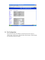
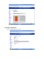
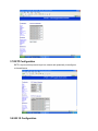
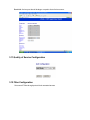
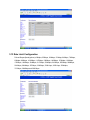
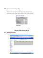
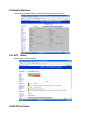
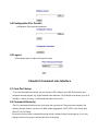
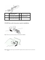
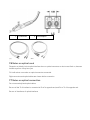
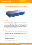
4 Ports + 3 SFP Gigabit Smart Switch Use Manual Ver.A0 Chapter 1 Product Specification 1.1 Product Characteristics Complies with IEEE802.3,IEEE802.3u,IEEE802.3ab standards; 4 10/100/1000Mbps Auto-Negotiation RJ45 ports supporting Auto-MDI/MDIX independent expansion slots supporting Mini GBIC module; Supports Web Smart and console managements ; Support IEEE802.3x flow control for half/full-duplex; Store and forward, integrated 8K MAC address table; Supports Port-Based /Tag VLAN Configuration; Supports rapid spanning tree(RSTP) Configuration; Supports Port Trunking; Supports port bandwidth control; Supports QoS function; Supports port mirror; Supports IGMP Snooping Configuration; Supports SNMP Configuration; Supports broadcast storm control; Supports HTTP software update,backup and reseting; Supports source IP filter through ports to block unwanted access; Supports dynamic flow statistics of ports; Supports circuit diagnoses; Standard 11-inch rack-mountable steel case; External power adapter supply; 1.2 Product Specifications Standards IEEE802.3, 802.3u, 802.3ab, 802.3x Wire-speed Performance MAC Address Auto-Learning and Auto-aging Basic Function IEEE802.3x flow control for Full-Duplex Mode and backpressure for Half-Duplex Mode Backbound 32Gbps Bandwidth MAC Address 8k Table and 3 SFP 10BASE-T: 14880pps/port Forwarding Rate 100BASE-TX: 148800pps/port 1000BASE-T: 1488000pps/port Transmission Store-and-Forward Method 4 10/100/1000Mbps Auto-Negotiation RJ45 ports (Auto MDI/MDIX) Ports and 3 SFP independence expansion slots supporting MiniGBIC modules 10Base-T: UTP category 3, 4, 5 cable (maximum 100m) EIA/TIA-568 100Ù STP (maximum 100m) Network Media 100Base-Tx: UTP category 5, 5e cable (maximum 100m) EIA/TIA-568 100Ù STP (maximum 100m) 1000Base-T: UTP category 5, 5e cable (maximum 100m) LED Indicators Power, 10/100M, 1000M Dimensions 250mm × 150mm × 44mm (W*D*H) Operating Temperature: 0℃~40℃ (32℉~104℉) Storage Temperature: -40℃~70℃ (-40℉~158℉) Operating Humidity: 10%~90% non-condensing Storage Humidity: 5%~90% non-condensing Input Power: 100-240VAC 50-60Hz Consumption Max:13W Environment 1.3 Package Contents 1 piece of 7-port Ethernet Switch 1 piece of external power adapter 1 piece of console cable 4 pieces of rubber padding User’s manual Chapter 2 Hardware Installation 2.1 Quick Installation Guide Choose a proper place for the rack mountable switch, considering the surroundings such as power source, space, keep it away from strong sunlight, heat source, and electromagnetism interference. Installation & Connection method: 1.Stick rubber paddings onto the bottom side of the switch. 2.Connect the switch to power source with offered power adapter, turn it on, the switch will test itself, all its indication lights are on at the same time, test is done when the lights go off after 5 seconds. 3.Connect the switch to network devices, including Lan cards, switches etc. with Cat3,4,5 cable(Cat5 recommended); related indication lights flash when attached network devices are working. ALL ports support Uplink. Note: Please not plug a phone line into a RJ45 port, otherwise it may cause damage. 2.2 LED Indications LED status Indication Power ON/OFF Power on/off Link/Act ON/OFF Ports connected/Ports unconnected FLASH Data frames running ON/OFF Maximum transmission rate 1000Mbps; Speed Maximum transmission rate 10/100 Mbps. Chapter 3 Configuration Guide 3.1 Fast Log on Notice: You may have to configure a new IP for a managing computer, because default switch IP is 192.168.2.1. You can log on as following steps: 1. Connect the switch with the managing computer Lan card; 2. Turn on the switch; 3. Make sure the managing computer IP address belongs to 192.168.2.2~254, e.g:192.168.2.100 4. Open IE browser , input http://192.168.2.1 and 'Enter', you will see login window as below: 5. Input Password (no password in default), and click“Apply”, configuration window comes as below: 3.2 System Configuration Here provides current switch status and you can set them according to your demands. MAC address: Software Version : Hardware Version : Active IP Address:192.168.2.1(in default ) Active Subnet Mask: 255.255.255.0(in default) DHCP Server:0(in default) Lease Time Left:0(default) 3.3 Port Configuration Here provides port status and available to set speed and flow control; options to 10M half-duplex, 10M full-duplex, 100M half-duplex,100M full-duplex, 1000M full-duplex, auto-negotiation(in default) and disable. 3.4 VLANs Configuration Can set 16 VLAN groups for 802.1q VLAN 3.5 Aggregation/Trunking Configuration 3.6 LACP Configuration LACP(IEEE 802.3ad Link Aggregation Protocol) provides a way to set up aggregation between switches automatically. 3.7 RSTP Configuration RSTP is a protocol that prevents loops in a network and dynamically it reconfigures to forward frames. 3.8 802.1X Configuration Here provides 802.1X process and available to set for each port of the switch. 3.9 IGMP Configuration 3.10 Mirroring Configuration Bandwidth of mirror port should be larger or equal to that of mirror source. 3.11 Quality of Service Configuration 3.12 Filter Configuration Set source IP filter through ports to block unwanted access. 3.13 Rate Limit Configuration Policer/ShaperSpeed(options):128kbps, 256kbps, 384kbps, 512kbps, 640kbps, 768kbps, 836kbps, 896kbps, 1024Mbps, 1152kbps, 1280kbps, 1408kbps, 1536kbps, 1664kbps, 1792kbps, 1920kbps, 2048kbps, 2176kbps, 2304kbps, 2432kbps, 2560kbps, 2688kbps, 2816kbps,,2944kbps, 3072kbps, 3200kbps, 3328 kbps, 3456 kbps, 3584kbps, 3712kbps, 3840kbps and 3968 kbps. 3.14 Storm Control Configuration Broadcast Control speed(options): 1kfps, 2fps, 4fps, 8fps, 16fps,32fps, 64fps, 128fps,256fps, 512fps, 1024fps, 2048fps, 4096fps, 8192fps, 16384fps, 32768fps. Chapter 4 Monitoring Guide 4.1 Statistics Overview Here provides statistics of current forwarding and receiving data. 4.2 Detailed Statistics Here provides detailed statistics of current forwarding and receiving data. 4.3 LACP Status Here provides LACP port Status. 4.4 RSTP Port Status Here provides RSTP port Status. 4.5 IGMP Status Here provides IGMP Status. 4.6 VeriPHY 4.7 Ping Ping function is used to test connection between the switch and destination. Chapter 5 Maintenance Guide 5.1 Warm Restart Warm Restart : click “Yes” to start restart the switch. 5.2 Factory Default Restore Factory Configuration: click “Yes” to default factory configuration. NOTICE: Please do login the switch window again after this configuration. please use a new IP address as you set, if you changed its default IP address before. 5.3 Software Upload Update process takes about 1 minute, the switch reboots automatically after software being updated, and re-login is required. 5.4 Configuration File Transfer Configuration File upload and download 5.5 Logout Please finally logout to make sure system security. Chapter 6 Command Line Interface 6.1 Com Port Set-up To use the command line interface you may connect a PC COM port to the RS-232 connector and activate a terminal program, e.g. HyperTerminal under Windows. The COM port must be set up to run 8 data bits, 1 stop bit, no parity, 115200 baud and without flow control. 6.2 Command Hierarchy The CLI is hierarchical with two levels: a top level and a group level. The group level consists of the following Groups: System ,Console, Port, MAC,VLAN, Aggregation, LACP, RSTP, User Group, QoS, Mirror, IP, Dot1X, Debug . At top level you may enter a command by giving the full command string, including group, or you may change context into a group by entering the name of the group. At group level you may enter commands for a particular group you have chosen without specifying the group name or you may return to the top level by entering the up command. The current level and group is indicated by the prompt. If you are at the top level, the prompt will be: >If you are at group level, the prompt will display the actual group, e.g. System >At group level you also have the option of using the slash (/) key to refer to a context relative to the top level. E.g. you may be in the system group and enter a /console/configuration command or change context into the console group by entering /console. 6.3 Login/Logout Procedures To get access to CLI you must login by entering a password. You will automatically be queried about the password.The password is configurable. The password check may be disabled by setting the password to an empty string “”, in which case any password entered during login will be accepted. You may logout at any time and at any context level using the “exit” command. 6.4 Help Utility You may get help by pressing the ? key or entering “help”. The help info depends on the context: At top level, a list of command groups is displayed. At group level, a list of the command syntaxes for the current group is displayed. If the help command is issued for a specific command, the command syntax and a description of the command are shown. 6.5 Example The command hierarchy and the help utility is demonstrated in the following example: > ? <enter> Commands at top level: System – System commands Console – Console commands Port – Port commands MAC - MAC table commands VLAN – VLAN commands Aggregation – Aggregation/Trunking commands LACP – IEEE802.3ad Link aggregation commands RSTP – IEEE802.1w Rapid Spanning Tree commands User Group QoS Mirror – User Group commands – QoS commands – Mirror commands IP – IP commands Dot1x – Dot1x commands Debug - Debug commands > console <enter> Console> ? <enter> Commands at Console level: Console Configuration Console Password [<password>] Console Timeout [<timeout>] Console Prompt [<prompt string>] Console> password ? Syntax: Console Password [<password>] Description: Set or display console password. The empty string (“”) disables the password check. [<password>]: Password string of up to 16 characters. Console> Chapter 7 Small Form Pluggable(SFP) 7.1 Specifications Optical transceivers support gigabit single/multi-mode, and transfer as far as 80 kms distance; original SFP modules are recommended to be used. Supportable optical transceivers are listed as following: SFP-GIG-SX Gigabit Ethernet optical transceiver(supports 850nm wavelength multi-mode, LC connector). Up to 550 meters through 50/125μm multi-mode fiber, and up to 275 meters through 62.5/125μm multi-mode fiber. SFP-GIG-LX Gigabit Ethernet optical transceiver(LC connector). Up to 10 kms through 1310nm wavelength single-mode fiber. SFP-GIG-LH40 Gigabit Ethernet optical transceiver(LC connector). Up to 40 kms through 1310nm wavelength single-mode fiber. SFP-GIG-LH80 Gigabit Ethernet optical transceiver(LC connector). Up to 80 kms through 1550nm wavelength single-mode fiber. 7.2 SFP fiber optic module components description 1 SFP fiber optic module specification label 4 Protective sliding rod 2 Incoming optical signal jack 5 Protective shield 3 Outgoing optical signal jack 7.3 SFP fiber optic transceiver module installation Step 1 Remove protective package and its protective shield Step 2 With the correct way to hold the SFP optical module, and insert it into a slot and in place Step 3 Insert it with right fiber optic cable. Matching fiber optic cables according to spec label are required to avoid of possible damage, and to get maximum effective transmission distance of optical signal. Step 4 Connect to network clients and insure correct working status by checking indication lights. 7.4 How to plug out SFP optical modules? 7.5 Notes on SFP optical module use Right fiber cables with LC connector to be adopted, and 1000M standard SFP module used. 7.6 Specification on fiber optic connection 1 LC connector 2 Limit shrapnel 7.6 Notes on optical used Please do not directly look at optical interface when no optical connectors or dust covers fixed on, because invisible rays from it may hurt eyes. Fix it with a dust cover when no optical connectors connected. Right connectors and optical cables are chosen before connection 7.7 Notes on optical connection Do not excessively bend optical cables. Be sure of that Tx of interface is connected to Rx of its opposite end, and Rx to Tx of its opposite end. Be sure of cleanliness of optical interfaces