1
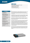
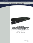
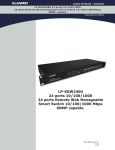
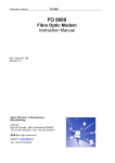
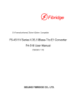
E1:Framed/unframed,75ohm/120ohm Compatible F5-4511 Series Ethernet to E1 Converter F4-51 User Manual (Version: 2.0) BEIJING FIBRIDGE CO.LTD. F4-51 Converter User Manual V2.0 Table of Content 1 2 3 Overview ....................................................................... 3 Features ........................................................................ 3 Specification ................................................................. 4 3.1 E1 interface................................................................. 4 3.2 Ethernet Interface ....................................................... 4 3.3 Size............................................................................. 5 3.4 Power ......................................................................... 5 3.5 Environment................................................................ 5 4 Appearance................................................................... 6 4.1 Front panel of standalone ........................................... 6 4.2 Back panel of standalone............................................ 6 4.3 Front Panel of Module ................................................ 7 4.4 LED Description.......................................................... 8 4.5 DIP Switch Description ............................................... 8 4.6 Bandwidth Selection ................................................. 12 5 Typical Application..................................................... 13 5.1 Point to Point ............................................................ 13 5.2 Star Topology ............................................................ 14 6 Order Information....................................................... 14 6.1 Model:....................................................................... 14 6.2 P/N:........................................................................... 14 -2- F4-51 Converter User Manual V2.0 1 Overview F5-4511 Series F4-51 converter is a high performance, remote, self-learning Ethernet bridge. Its compact size and low cost make it ideal for cost-sensitive bridging applications, or as a LAN extender over bit stream type infrastructures. Its E1 data interface also provides an economical digital access solution for E1 and Fractional E1 network Services, which can work at data rates of 64Kbps to 2048Kbps. User data is placed into the E1 frame, using only the required number of timeslots. Timeslot assignment is accomplished according to the Data Port speed and manual setting of DIP switches. The main E1 link may be clocked from the recovered receive clock or from an internal oscillator. For easy to check the fault of network line, the device provides loop selection, both local loop and remote loop. 2 Features z z z z z High performance bridge for 10Base-T Ethernet extension Fully compatible with IEEE 802.3 and Ethernet Standards E1 channel: framed and unframed optional, 75/120ohm optional Ethernet Port: 10Mbps, Full/Half Duplex Mode compatible 10Base-T LAN Interface on RJ-45 connector and -3- F4-51 Converter User Manual V2.0 z z z z z MDI/MDI-X optional Allow transmitting and receiving VLAN data packet 15000 frames per second filtering and forwarding rate 1000 MAC address LAN table, and automatic LAN table learning and aging. Standalone and 16 slots chassis optional Power of Chassis: 2 Slots for slide in power supplier module, AC or DC power supplier module, Redundant Power supported 3 Specification 3.1 E1 interface Data rate: N*64Kbps, N=1~32 Code type: HDB3 Compliant with G.703, G.704 Line impedance:75Ω(Unbalanced) / 120Ω(Balanced) Connector: BNC(75Ω) / RJ45(120Ω) Jitter: Compliant with ITU-T G.742 and G.823 Framed / unframed optional Definition of RJ45 connector(120Ω E1 balanced): PIN 1 2 4 5 3,6 Others Function TX- TX+ RX- RX+ GND Reserved 3.2 Ethernet Interface Compatible with IEEE802.3 Speed: 10Mbps -4- F4-51 Converter User Manual V2.0 Full/Half duplex auto negotiate Connectors: RJ-45 Connector Transfer distance: <150m 3.3 Size Standalone: 252 (W)×136 (D)×40 (H)mm Module: 220 (L)×176(W)×25.3(H) mm 16-slot chassis: 19 inch(W)×340mm (D)×4U (H) 3.4 Power Power supply: AC Power: 100V-240V, 0.4-0.2A, 50-60 Hz DC Power: -48V, 0.4A Power consumption <3W 3.5 Environment Operation Temperature: 0℃~50℃; Humidity: 90%(non-condensed) Air pressure: 86kPa~106 kPa. Transport and store Temperature: -20℃~60℃; Humidity: 95%(non-condensed) Air pressure: 86kPa~106 kPa -5- F4-51 Converter User Manual V2.0 4 Appearance 4.1 Front panel of standalone DIP Switch LOOP Button LED Power Switch Figure1 Front Panel of Standalone 4.2 Back panel of standalone 220VAC -48VDC Power IN Power IN E1 Port 75/120ohm Ethernet Port Selection Figure2 Back Panel of Standalone Note: 220VAC & -48VDC power input are alternative, in one device, there is only one kind of power input. -6- F4-51 Converter User Manual V2.0 4.3 Front Panel of Module LEDs E1 Port Figure3 Front Panel of Module -7- F4-51 Converter User Manual V2.0 4.4 LED Description Table 1 LED Description Indicator Color Status Description RXD Yellow Blink Receiving data TXD Yellow Blink Transmitting data LINK Green ON Ethernet port link OK FDX Green ON Ethernet is working at Full Duplex mode LOS Red ON E1 link signal loss LOF Red ON E1 synchronization loss COL Red ON Ethernet line collision LOOP Green ON Indicate Local Loop Status POWER Green ON Power supply OK 4.5 DIP Switch Description Refer to the following tables for the functions of the DIP switches located along the both of the front and back side of the F4-51. F4-51 provides a total of 5 DIP switches for timeslot selection(see table 2 for detail). But please NOTE when you select unframed mode (set pin 7 of SWITCH1 ON), the timeslot setting does no function. Fractional E1 uses only a fraction of the total available timeslots. For example, if you wish to translate only 192K from a 2048K E1 line, you only need to set two pins, pin1 and pin2 -8- F4-51 Converter User Manual V2.0 of SWITCH1, OFF and set three pins, pin3-5 of SWITCH1, ON. Table 2 Function Description of Switch/SW5 BIT Status ITEM Switch SW5 1 8 ON BW0 BW0-BW4 are used as Binary Code and can 2 7 BW1 3 6 BW2 4 5 BW3 5 4 BW4 6 3 NA 7 2 E1-FULL 8 1 TIM-MOD OFF provide 32 different kinds of Bandwidth. BW4 is the MSB, BW0 is the LSB. When is ON , it means 0, when is OFF, it means 1. See Table 6 to get more details. These settings will be ignored when Bit7 “Full/Fabr” is set OFF. Not Available Not Available Framed(Fractional) Unframed(Full) mode mode Recovered Clock Internal Oscillator Note: “Switch” is for standalone, and “SW5” is for module. -9- F4-51 Converter User Manual V2.0 Table 3 75/120ohm selection or SW6 Setting BIT For 75 ohm Selection For 120 ohm 1 OFF ON 2 ON OFF 3 ON: TRIP is connected to ground OFF: TRIP is opened OFF 4 ON: RRIP is connected to ground OFF: RRIP is opened OFF Default: Bit 1-4: OFF ON ON ON Note: “75/120ohm Selection” is for standalone, and “SW6” is for F4-51 module Card. Table 4 E1_LP Button or JP4 Jumper Descriptions E1_LP JP4 Up 2-3 short None loop, work as normal 1-2 short Loop mode, usually used to check the fault of the network line. To configure either Local loop or Remote loop, please see table 5. Down Description Table 5 LP_MODE Button or JP5 Descriptions LP_Mode JP5 Description Up 1-2 short Remote Loop, only available on Fractional (framed) Mode Down 2-3 short Local Loop - 10 - F4-51 Converter User Manual V2.0 Explanation: 1) UP is corresponding to , Down is corresponding to 2) Short is corresponding to 1-2 short 2-3 short NOTE: 1. Before you select remote loop or local loop, you should set E1_LP down first; 2. Local Loop Back is available both in framed mode and in unframed mode; 3. Remote Loop Back is only available in framed mode. In other words, if you want to use remote loop, you should set the bit7 of "SWITCH"(on the front panel of the device) ON. (see table 2 of the technical datasheet); 4. If Unit A(F4-51) is at internal clock, Unit B(F4-51) is at recovered clock, and there is no other based clock in the whole network line, you can't set Unit B(F4-51) on remote loop. 5. Unit A’s local loop back: Unit A’s remote loop back: - 11 - F4-51 Converter User Manual V2.0 4.6 Bandwidth Selection Table 6 Bandwidth Selections No. BW4 BW3 BW2 BW1 BW0 1 ON ON ON ON ON N.A. 2 ON ON ON ON OFF 64Kbps 3 ON ON ON OFF ON 128Kbps 4 ON ON ON OFF OFF 192Kbps 5 ON ON OFF ON ON 256Kbps 6 ON ON OFF ON OFF 320Kbps 7 ON ON OFF OFF ON 384Kbps 8 ON ON OFF OFF OFF 448Kbps 9 ON OFF ON ON ON 512Kbps 10 ON OFF ON ON OFF 576Kbps 11 ON OFF ON OFF ON 640Kbps 12 ON OFF ON OFF OFF 704Kbps 13 ON OFF OFF ON ON 768Kbps 14 ON OFF OFF ON OFF 832Kbps 15 ON OFF OFF OFF ON 896Kbps 16 ON OFF OFF OFF OFF 960Kbps 17 OFF ON ON ON ON 1024Kbps 18 OFF ON ON ON OFF 1088Kbps 19 OFF ON ON OFF ON 1152Kbps 20 OFF ON ON OFF OFF 1216Kbps 21 OFF ON OFF ON ON 1280Kbps 22 OFF ON OFF ON OFF 1344Kbps 23 OFF ON OFF OFF ON 1408Kbps 24 OFF ON OFF OFF OFF 1472Kbps - 12 - Bandwidth F4-51 Converter User Manual V2.0 25 OFF OFF ON ON ON 1536Kbps 26 OFF OFF ON ON OFF 1600Kbps 27 OFF OFF ON OFF ON 1664Kbps 28 OFF OFF ON OFF OFF 1728Kbps 29 OFF OFF OFF ON ON 1792Kbps 30 OFF OFF OFF ON OFF 1856Kbps 31 OFF OFF OFF OFF ON 1920Kbps 32 OFF OFF OFF OFF OFF 1984Kbps 5 Typical Application 5.1 Point to Point F4-51 E1 Line F4-51 In the above application, it is recommended that user select one F4-51 device’s timing signal as unique timing source, and all the other equipment follow this timing source. F4-51 should be used in pairs. - 13 - F4-51 Converter User Manual V2.0 5.2 Star Topology E1 Channel F4-51 Ethernet Switch 16-slot Converter E1 Channel F4-51 Data Center User End 6 Order Information 6.1 Model: F5-4511, Ethernet to 1-8 E1 Protocol Converter Series 6.2 P/N: F4-51A 10Base-T to E1 Converter, Standalone Device, 220VAC Power input F4-51D 10Base-T to E1 Converter, Standalone Device, -48VDC Power input F4-51M 10Base-T to E1 Converter, Module Card FC-416 16 Slots Chassis, Supply two Powers - 14 -