1
FA1600C/CA/CB Installation and Setup Guide
•
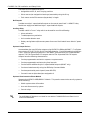
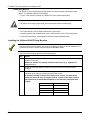
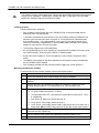
Use wires having insulation rated for at least 90°C operation and suitable for non-powerlimited applications.
•
Use care to keep 18VAC wiring separated from all other wiring inside the panel’s enclosure.
This must be done by running non-power-limited 18VAC wiring into the panel’s enclosure via
one of the knockouts on the left-hand side of the enclosure, and then tie-wrapping these wires
to the tie-wrap loops located near the knockout.
5. Replace the front cover of the enclosure and fasten with the screws supplied.
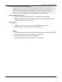
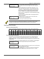
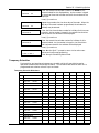
A few seconds after power is applied to the control, the keypad should display
"DISARMED...READY TO ARM." If there is no keypad display, check that the Transformer
is supplying proper voltage to the panel (about 17-19.5VAC when the power line voltage is
110-120VAC).
Earth Ground Connections
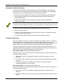
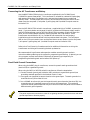
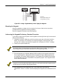
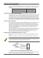
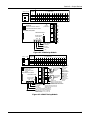
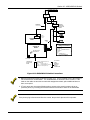
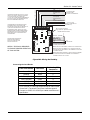
When using the N8167 plug-in transformer, connect the panel’s earth ground terminal
(terminal 30) to a good earth ground.
When using the 1451 (or 1451-24) wired-in transformer, follow the steps below:
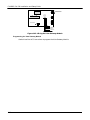
1. Connect the earth ground post inside the 1451 enclosure to a good earth ground (use
grounding methods specified in the National Electric Code). Use a green wire nut
(supplied) to secure the wire to the ground post.
2. Run a 16AWG wire from this post to the panel’s earth ground terminal (terminal 30).
Use a second green nut (supplied) to secure this wire to the ground post. This method of
connection avoids ground loops that may occur when the 1451 and panel are connected to
different earth ground systems.
The panel requires this connection in order for its lightning transient protection devices and earth
ground supervision to function properly.
Backup Power Calculations
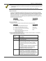
In the event of an AC power loss, the FA1600C/CA/CB control (and PS24 Power Supply
Module, if used) must be supported by a backup, rechargeable, lead acid (gel cell type)
battery. When used without a PS24, a 12VDC, 7AH min./34.4AH max. battery must be
connected to the FA1600C/CA/CB control. When used with the PS24, two 12V, 7AH
min./17.2AH max. batteries must be connected to the PS24. The PS24 configures these
batteries to provide 24V backup power to its outputs, and 12V backup power to the control.
The battery's capacity must be sized to provide 4 hours (residential burglary installations) or
24 hours (residential fire or commercial central station fire installations) or 60 hours
(commercial remote fire installations) of standby time followed by 4 minutes (residential fire
and/or burglary installations) or 5 minutes (commercial fire installations) or 15 minutes
(commercial burglary installations) of alarm time. This can be determined as follows:
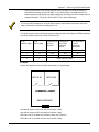
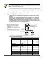
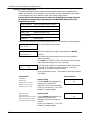
1. If using the polling loop, fill out the Polling Loop Current Draw Worksheet, shown below,
to determine the total current drawn from the polling loop.
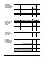
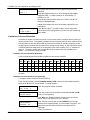
2. Fill out the Total Control Panel Load Worksheet, shown below, to determine the total
standby and alarm load drawn from the control's internal 12V power supply.
3. If using the PS24, fill out the Total PS24 Module Load Worksheet, found in the PS24's
instructions, to determine the required capacity of the backup batteries that must be
connected to the PS24. Select two 12V batteries from the Battery Selection Table in the
PS24's instructions that have a capacity greater than or equal to the calculated capacity.
20-2