1
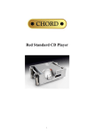
welcome Thank you for buying a Chord product. Before you start to enjoy using to your Chord product, please take a couple of minutes to read how to connect your audio equipment and loudspeakers to your pre-amplifier or integrated amplifier and how to maximize your listening experience. user guide for integrated amplifiers CPM 2650, CPM 3350 Chord’s integrated amplifiers are based on a combination of our highly successful pre-amplifiers and power amplifiers together with a few features of their own. The power amplifier is based on Chord’s tried and tested technology of ultra high frequency ESR power supply which has the ability to store more energy far more efficiently than conventional designs. A variety of outputs means that you can choose to drive up to two sets of loudspeakers, use your integrated amplifier as a pre-amplifier or use it in conjunction with another power amplifier for bi-amping. 1 background We want you to be confident using your new Chord amplifier. You’re probably an audiophile with extensive knowledge of audio equipment. However, you may not be! So in the following section we explain a few basics to help you get started, or get you back up to speed if you’re a little rusty. connecting your equipment Chord amplifiers are supplied with and designed to be connected using balanced inputs. The interconnecting cables you use will depend on the available input and output sockets on your other equipment. We have installed unbalanced inputs on all Chord equipment, thus enabling you to mix Chord and other manufacturer’s equipment. Balanced inputs carry twice the strength of signal of unbalanced inputs and are able to PUSH 1 be fed down long lengths of cable with less deterioration of signal. They are also less prone to interference than unbalanced inputs. Balanced inputs have three pins and use Neutric XLR style connectors. Pin 1 is earth, pin 2 is positive and pin 3 is negative. Unbalanced inputs use RCA phono connectors which are gold plated with teflon high performance dielectric insulators for optimum performance. speakers outputs inputs power amplifier outputs inputs pre-amplifier CD player audio source tuner 2 or integrated amplifier when setting up To ensure that your Chord integrated amplifier works efficiently and safely, please pay particular attention to the following issues. ventilation Your Chord integrated amplifier should have at least 5cm of clear space all around it to ensure a free flow of air at all times. When driven continuously at well above average levels, the temperature at the back of the unit may exceed 50 ºC. This is normal and no cause for concern, although it does highlight the need for adequate ventilation around the unit. We recommend that you do not place your integrated amplifier directly on a carpet. mains lead and plug All Chord equipment comes supplied with the correct mains lead and plug. This should be used at all times. if you need to fit a plug for UK/Europe Connect the blue wire to the neutral terminal Connect the brown wire to the live terminal Connect the yellow/green wire to the earth terminal if you need to fit a plug for US/Canada Connect the white wire to the neutral terminal Connect the black wire to the live terminal Connect the green to the earth terminal earthing issues in Europe In some European countries a hum may occur if your integrated/pre-amplifier is connected to mains sockets that do not have an earth. If this is the case please ensure that: 1. Your integrated/pre-amplifier is connected via a multi-way mains block which contains an earth point at each socket outlet. This is to ensure that the chassis metalwork of each item is connected together. 2. Use the connecting points on your Chord unit and connect to an available earth point. 3. We recommend that an earthing method for your building is implemented. safety warnings It is important that your integrated/pre-amplifier is earthed at all times via its own mains lead. Failure to do this may be hazardous. The power supply components within the amplifier are designed to be operated at lethal voltages and energy levels. Circuit designs that embody these components conform with applicable safety requirements. Precautions must be taken to prevent accidental contact with power-line potentials. Do not connect grounded test equipment. These units comply with EN 5008 1-1 and IEC 80 1/2 3 outputs on the CPM 2650 CPM 2650 You need to connect the outputs on the back of your integrated amplifier to your loudspeakers. You can use any speakers that match the output power of your amplifier. Note that the lower the impedance of your speakers the higher the output power. connecting to your loudspeakers 1. The loudspeaker connections are via two heavy duty WBT gold plated binding posts labelled O/P 1 and these should be connected to your speakers. 2. On your remote control press HIFI and then OP 1 to output the signal to your loudspeakers. Note: The WBT rhodium plated 4mm speaker binding posts will accept 4mm banana plugs (WBT-0645 or WBT-0644) or 6mm spades (WBT-0680). Making connections using bare wire is not recommended. using your integrated amplifier as a pre-amplifier You can use your integrated amplifier as a pre-amplifier to provide a signal for another power amplifier. 1.Use RCA style connectors to connect Right O/P 2 to the Right IN on your power amplifier, and connect Left O/P 2 to the Left IN on your power amplifier. 2.On your remote control press HIFI and then OP 2 to output the signal to the power amplifier. 4 if you want to bi-amp Bi-amping is a technique where you use one amplifier to drive the woofers (low frequencies) and another to drive the tweeters (mid and high frequencies). 1. Connect your loudspeakers’ low frequency inputs to the binding posts labelled Right and Left O/P 1. 2. Use RCA style connectors to connect Right O/P 2 to the Right IN on your power amplifier, and connect Left O/P 2 to the Left IN on your power amplifier. 3. Connect the outputs of your power amplifier to your loudspeaker’s high frequency inputs. Remove any shorting links in the speaker binding posts. 4. On your remote control press HIFI and then OP 1+2 to select both outputs 1 and 2. See Figure 2 on page 20 for more details. 5 inputs on the CPM 2650 CPM 3350 You can connect up to six items of source input equipment, such as CD player, Video, Tuner etc. to the inputs on your pre-amplifier or integrated amplifier. connecting to a CD or record player unit 1. Use either XLR or RCA connectors to the left and right pairs marked DISC 1 or DISC 2. 2. You can connect to either of the left/right pairs numbered 1 or 2, but not both 1s PUSH PUSH 1 1 2 2 3 3 PUSH PUSH 1 2 3 1 2 3 or both 2s at the same time. Note: All record players need to be connected to a separate phono head amplifier like the Chord Phono Stage before connecting to this product. connecting to a Video, DVD or other products Use RCA connectors to the left and right pairs marked V. connecting to a Tuner/Radio or Satellite receiver Use RCA connectors to the left and right pairs marked R. connecting to a Tape recorder: Use RCA connectors to the left and right pairs marked IN T1 or T2. if you want to tape record Refer to page 12 for more information. 6 tape recording You can tape record an input from another audio source or two sources at the same time. If you’ve been using a tape recorder as an input source, it will already be connected to the T1 or T2 IN sockets. If you haven’t, first connect the tape’s output to the T1 or T2 IN sockets. connecting to a Tape recorder to tape an audio source Use RCA connectors to the left and right pairs marked OUT T1 or T2, or both. CPM 2650, CPM 3350 selecting the bus Your amplifier has two input selection buses. The default bus is bus A and this is the one you would use to choose your inputs in everyday operation. The advantage of having two buses is that it allows for two tape recorders to tape (different inputs) simultaneously. Bus A is permanently connected to the Tape 2 (T2) output and Bus B is permanently connected to Tape 1 (T1) output which prevents you from accidentally taping to and from the same machine. You can tape from any source to either of the tape recorder outputs and both outputs can be monitored. For example you can play a CD on Disc 1 on Bus A and connect your tape recorder to the Tape 2 output while you play a record on Disc 2 on Bus B and connect another tape recorder to the Tape 1 output. Simply switch between Bus A and Bus B to monitor either of the sources. 7 everyday use turning on your integrated amplifier 1. When you plug your amplifier into the mains using the supplied mains lead the power indicator on the front panel will glow red which means that the amplifier is in standby mode. 2. Press the power button beneath the power indicator and after a few seconds it will glow green indicating that the amplifier is ready for use. automatic shutdown 1. If there is a major overload or short circuit the integrated amplifier will detect this and shut down automatically and the power indicator will fade and switch to red. The integrated amplifier should then be switched off immediately at the mains. 2. When the fault has been rectified the integrated amplifier can be switched on and will power up as usual. You should wait at least two minutes before turning the integrated amplifier on again at the mains to allow the power supply protection circuitry to reset itself. select your input source Your integrated/pre-amplifier Press button A to Press button B to uses input bus A by default select: select: and the display will read . To scroll through the other input sources press button A. Press button B to select Bus B. It is indicated by a dot displaying between each letter . adjusting the volume Use the volume knob to adjust the volume manually. changing the balance Use the balance knob to shift the balance between the left and right loudspeaker. 8 using the remote control The Stealth Remote control is a universal controller for all Chord products. This can provide a totally integrated audio solution. For full information please consult the additional remote control manual provided. For optimum use hold your remote control flat and point it directly at your integrated amplifier. 9 selecting your input source 1. Press HIFI then Bus-A. 2. Press one of: Disc 1, Disc 2, Tape 2, Video or Radio. adjusting the volume 1. Press the button marked Vol + to increase the volume. 2. Press Vol - to decrease the volume. The volume chosen will be displayed on the digital display with figures from 0 to 98. choosing your output 1. Press OP 1 if your output is connected to O/P 1 on the back of your integrated amplifier. 2. Press OP 2 if you are using the line output from O/P 2 on the back of your integrated amplifier. 3. Press OP 1+2 if you are bi-amping. Note: With the CPM2650 and CPM3350 integrated amplifiers, O/P 1 is internally connected to the internal amplifier stage. O/P 2 is the pre-amplifier output for connecting to an additional external amplifier. changing the balance 1. Press the balance button marked Bal + to move the balance to the right. 2. Press Bal - to move the balance to the left. The direction you are moving the balance towards will be displayed on the digital display. mute 1. Press Mute to mute the amplifier. to unmute 1. Press Mute again to unmute or 2. Press the volume buttons up or down or 3. Turn the volume knob on your amplifier up or down. 10 input gain control CPM 3350 You can adjust the input gain on your input devices so that you can align the volume levels of your different inputs There are four settings which are x1, x1.5, x1.75 and x2. This feature is not available on the CPA 2500 and the CPM 2650. Most modern input devices such as CD players have an unbalanced output voltage of 2V and a balanced output of 4V which does not require any additional gain. In fact, to increase the gain on such an output level can lead to a distortion of the signal.However, older audio equipment may have an output voltage of less than 2V, in which case you may like to adjust the input gain. increasing the input gain 1. Using your remote control press HIFI and then the input device of your choice (eg Disc 1). The display will show: . 2.Press BUS-A (or BUS-B if you are going to record from the Tape 1 output). The display will show: 3.Press the volume button marked Vol+ to increase the gain to x1.5. The display will show: 4.Repeat steps 2 and 3 to increase the gain to x1.75, and repeat these steps once again to increase the gain to x2. reducing the input gain 1. Using your remote control press HIFI and then the input device of your choice (eg Disc 1). The display will show: 2.Press BUS-A (or BUS-B is you are going to record from the Tape 1 output). 3.Press the volume button marked Vol- to decrease the gain. 4.Repeat steps 2 and 3 to reduce the gain again. Once you have adjusted the gain setting on an input device your amplifier will remember the setting, even if it is switched off for many months. to reset all gain levels to x1 on Bus A and Bus B 1. On the front of your amplifier press and hold the A button for three seconds. The display will show a gain setting. 2. Press and hold the Set(S) button until you see RESET Release the button and the display will show five dashes. 3. Select a source on either bus system. 11 maintenance adjusting the settings Always remember to make any changes to settings with the volume set low or an instant burst of sound could damage your loudspeakers cleaning To clean finger marks and other blemishes from your amplifier spray clear glass cleaner onto a soft lint free cloth and then use the cloth to gently clean your amplifier. changing the batteries in the remote control Simply undo the four small cross head screws on the side of your remote control. You may need to run a sharp knife along the join to remove the battery casing, then replace with four new AAA batteries as shown inside the battery compartment. servicing There are no user serviceable parts in your Chord amplifier, and it should only be serviced by Chord Electronics Limited or their expressly approved Service Agents. 12 frequently asked questions why aren’t any of the remote control buttons working? Press HIFI to set up the remote control for pre-amplifier functions. I’ve connected all the wires up but I can’t hear any sound? Ensure that you’ve selected the correct bus (typically Bus A), the correct input (eg Disc 1) and the correct output (eg Output 1). why is there no display when I’ve turned the amplifier back on? You need to wait for two minutes after switching the unit off before switching it on again. why is there humming coming from the loudspeakers? Check that you’ve earthed the unit. The interconnects need to be properly screened and placed away from mains cables. Interference can be reduced by using balanced inputs and outputs instead of RCA phono types. the sound coming from the loudspeakers is distorted Check that the speakers are connected properly. It may be that the volume is turned up too loud for your speakers or that you have set the gain for the input device too high. the amplifier was in standby mode and has turned itself off Changing connections while the amplifier is on, for example, dropping the stylus onto a record can cause the unit to shutdown. Check that the speaker cables have no stray inner core wires touching each other as this can cause a short circuit. 13 bi-amping HF LF LF HF speakers outputs inputs outputs inputs O/P2 power amplifiers O/P1 outputs inputs pre-amplifier Figure 1: Bi-amping for a pre-amplifier HF LF LF HF speakers outputs inputs power amplifier O/P2 O/P1 outputs inputs Figure 2: Bi-amping for an integrated amplifier 14 integrated amplifier Product Specifications CPM2650 Pre-Amp Section Unbalanced Inputs: Balanced Inputs: Outputs: Intermodulation Distortion: Signal to Noise Ratio: Frequency Range: Harmonic Distortion: Channel Separation: Channel Balance: Input impedance: Pre-amp Output impedance: Output Offset: Video, Radio, Tape1 and Tape2 Disc 1, Disc 2 are 3-pin female XLR inputs both with RCA Phono style input sockets wired asymmetrically in parallel 2 x RCA Phono style, gold-plated with Teflon dielectric insulation -100dB all inputs -93dB all inputs 2.5Hz – 200kHz (-3dB) 10 Hz –91dB, 1kHz –93dB, 10kHz –90dB, 20kHz –87dB 10 Hz 90dB, 1kHz 90dB, 10kHz 90dB, 20kHz 85dB 0.01dB Unbalanced 47kOhms, Balanced 94kOhms (Disc 1 & Disc 2) 470 ohms 0mV both channels Power Amp Section Output Power: Signal To Noise Ratio: Channel Separation: Output Impedance: Output Inductance: Output Connections: Slew rate: Gain: Stability: 120W rms per channel @ 0.05% distortion into 8 Ohms 170W rms per channel into 4 Ohms 180W rms per channel into 8 Ohms 220W rms per channel into 4 Ohms -1dB, 0.8Hz to 46kHz (8 Ohms) -3dB, 0.8Hz to 77kHz (8 Ohms) -1dB, 0.8Hz to 39kHz (4 Ohms) -3dB, 0.8Hz to 75kHz (4 Ohms) Better than –103dB, ‘A’ weighted two thirds -80dB 0.03 Ohms 2.6mH 2 x gold plated WBT connections 70V per S, 1kHz 20V square wave 30dB Unconditional Dimensions: Weight: 420mm (w) x 355mm (d) x 133mm (h) 16Kg Dynamic Headroom: Frequency Response: CPM3350 Pre-Amp Section Unbalanced Inputs: Balanced Inputs: Outputs: Intermodulation Distortion: Signal to Noise Ratio: Frequency Range: Nominal Gain: Harmonic Distortion: Channel Separation: Channel Balance: Input impedance: Output impedance: Output Offset: Video, Radio, Tape1 and Tape2 Disc 1, Disc 2 are 3-pin female XLR inputs both with RCA Phono style input sockets wired asymmetrically in parallel 2 x RCA Phono style, gold-plated with Teflon dielectric insulation -100dB all inputs -93dB all inputs 2.5Hz – 200kHz (-3dB) All inputs subject to 4 levels of gain (x1, x2, x5, x7) 10 Hz –91dB, 1kHz –93dB, 10kHz –90dB, 20kHz –87dB 10 Hz 90dB, 1kHz 90dB, 10kHz 90dB, 20kHz 85dB 0.01dB Unbalanced 47kOhms, Balanced 94kOhms (Disc 1 & Disc 2) 100 ohms 0mV both channels Power Amp Section Output Power: Dynamic Headroom: Frequency Response: Signal To Noise Ratio: Channel Separation: Output Impedance: Output Inductance: Output Connections: Slew rate: Gain: Stability: Dimensions: Weight: 220W rms per channel @ 0.05% distortion into 8 Ohms 300W rms per channel into 4 Ohms 300W rms per channel into 8 Ohms 520W rms per channel into 4 Ohms -1dB, 0.8Hz to 46kHz (8 Ohms) -3dB, 0.8Hz to 77kHz (8 Ohms) -1dB, 0.8Hz to 39kHz (4 Ohms) -3dB, 0.8Hz to 75kHz (4 Ohms) Better than –103dB, ‘A’ weighted two thirds -75dB 0.03 Ohms 2.6mH 2 x gold plated WBT connections 70V per S, 1kHz 20V square wave 30dB Unconditional 420mm (w) x 355mm (d) x 133mm (h) 19Kg 15 Chord Electronics limited The Pumphouse Farleigh Bridge Farleigh Lane East Farleigh Kent ME16 9NB Tel: +44 (0)1622 721444 Fax: +44 (0)1622 721555 Email: [email protected] http://www.chordelectronics.co.uk 16