1
University of Twente
EEMCS / Electrical Engineering
Control Engineering
Endstops for the Mechatronic Demonstrator
Albert Post
Individual Design Assignment
Supervisors:
prof.dr.ir. J. van Amerongen
dr.ir. J.F. Broenink
ir. M.A. Groothuis
A.P. de Vries
June 2008
Report nr. 013CE2008
Control Engineering
EE-Math-CS
University of Twente
P.O.Box 217
7500 AE Enschede
The Netherlands
i
Summary
The mechatronic demonstrator is developed for students to learn the theoretical aspects of control
engineering and to apply this theory in practice. The demonstrator is provided with a hardware safety
layer for personal security and to prevent damage. The safety layer exists of two end switches which
disable the motor amplifier, when the slider pushes a switch. This layer prevents that the motor
damages the demonstrator. The old safety layer is not sufficient and the end stops have too little
functionality.
In this individual design assignment an analysis has been done to solve the problems and
improvements concerning the safety layer of the mechatronic demonstrator. Especially the end stop
functionality of the demonstrator needs to be analyzed. Three items of the end stops have to be
improved. The first item is the motor brake when an end stop is pushed. The second item is the
direction dependency of the slider when an end stop is active. And the last imperfection is that the end
stops do not support the homing of the slider.
These imperfections are improved and new functionality is implemented on a printed circuit board.
The motor brake is improved with a TRIAC. The TRIAC short circuits the motor to decelerate faster
instead of the previous disabling of the motor amplifier. Further, the end switches are now direction
dependent, allowing the slider always to move away from the end switch. Furthermore the end stops
are connected to the computer. With this end stop information a homing operation is added. This
bachelor assignment has resulted in an increased end stop functionality of the mechatronic
demonstrator.
Some recommendations are presented in this report:
•
A software safety layer is recommended. This software prevents that the slider does not touch
the end stops and so, it improves the solutions of some problems.
•
Implement a slider velocity limiter is software. The slider velocity has to limit to
approximately 1.5 m/s.
•
Implement the detection of the marker in the homing operation, because this detection is
currently not implemented in the homing operation. Furthermore, examine the efficiency of
the homing speed.
•
Change the current timing belt for a stronger one, and replace the pulleys for bearing pulleys
to pre-tension the belt.
Control Engineering
ii
End stops for the Mechatronic Demonstrator
Samenvatting
De mechatronic demonstrator is een opstelling voor studenten om theoretische aspecten van de
regeltechniek te leren en toe te passen in de praktijk. De demonstrator is voorzien van een
hardwarematige veiligheidslaag voor persoonlijke veiligheid en ter voorkoming van schade aan de
opstelling. De huidige beveiliging bestaat uit twee eindschakelaars die de motorversterker buiten
werking stellen wanneer de slider een schakelaar aanraakt. Op deze manier wordt voorkomen dat de
motor schade aan de opstelling toebrengt. De oude veiligheidslaag is niet voldoende en heeft te weinig
functionaliteit.
In deze individuele onderzoeksopdracht is een analyse uitgevoerd naar problemen en verbeteringen
met betrekking tot de veiligheidslaag van de mechatronic demonstrator en in het bijzonder de
functionaliteit van de eindschakelaars. Drie aspecten van de schakelaars moeten verbeterd worden. Het
eerste punt is het remmen van de motor wanneer een eindschakelaar is ingedrukt. Het tweede punt is
richtingsafhankelijkheid van de slider, wanneer een eindschakelaar is geactiveerd. Het laatste punt is
dat de eindschakelaars geen initialisatie van de slider positie ondersteunen (homing).
Bovenstaande punten zijn verbeterd en nieuwe functionaliteit is toegevoegd en gerealiseerd op een
printplaat. Het remmen van de motor is verbeterd met behulp van een TRIAC. De TRIAC sluit de
motor kort waardoor de deceleratie van de motor sneller wordt, in tegenstelling tot de vorige
uitschakeling van de motor versterker.Verder is de richtingsafhankelijkheid van de slider
geïmplementeerd. Hierdoor kan de slider zich altijd van de eindschakelaar verwijderen. Ook zijn de
eindschakelaars op de computer aangesloten. Met behulp van deze data is een homing operatie
gemaakt met 20SIM. De andere eindschakelaar functies zijn gerealiseerd op een printplaat. Dit
onderzoek heeft uiteindelijk geleidt tot verbetering van de functionaliteit van de eindschakelaars van
de mechatronic demonstrator.
Enkele aanbevelingen komen naar voren in dit verslag:
•
Een software veiligheidslaag wordt aanbevolen. De software voorkomt dat de slider de
eindschakelaars aanraakt. Deze software verbetert de bestaande oplossing.
•
Het implementeren van a snelheidsbegrenzer in software, zodat de slidersnelheid begrensd
wordt op ongeveer 1,5 m/s.
•
Toevoegen van de detectie van de marker in de homing. Deze functie zit nog niet in de
bestaande homing functie. Verder kan de efficiency van homing snelheid onderzocht worden.
•
Vervang de huidige tandriem voor een sterker exemplaar en vervang de pulley’s voor
gelagerde pulley’s om de tandriem beter op spanning te kunnen brengen.
University of Twente
iii
Contents
1
Introduction ....................................................................................................................... 2
1.1
Mechatronic Demonstrator .....................................................................................................2
1.2
Problem description ................................................................................................................2
1.3
Objective.................................................................................................................................2
1.4
Requirements ..........................................................................................................................2
1.5
Outline of the report................................................................................................................2
2 Analysis of the functionality of the end stops .................................................................... 2
2.1
Characterization of the demonstrator......................................................................................2
2.1.1 Characterization of the motor brake ...................................................................................2
2.1.2 Characterization of the motor control.................................................................................2
2.1.3 Characterization of the homing ..........................................................................................2
2.2
Alternatives.............................................................................................................................2
2.2.1 Motor brake alternatives.....................................................................................................2
2.2.2 Short circuit alternatives.....................................................................................................2
2.2.3 Direction sensor alternatives ..............................................................................................2
2.2.4 Homing alternatives............................................................................................................2
2.3
Additional restrictions.............................................................................................................2
2.3.1 Maximum deceleration.......................................................................................................2
2.3.2 Maximum current ...............................................................................................................2
2.3.3 Maximum velocity..............................................................................................................2
2.3.4 Maximum stop distance......................................................................................................2
2.4
Conclusion ..............................................................................................................................2
3 Method to improve the end stop functionality.................................................................... 2
3.1
Chosen methods......................................................................................................................2
3.1.1 Brake method .....................................................................................................................2
3.1.2 Direction dependency method ............................................................................................2
3.1.3 Homing method ..................................................................................................................2
3.2
Block diagram.........................................................................................................................2
3.3
Electric circuits .......................................................................................................................2
3.3.1 Electric circuit of the motor brake......................................................................................2
3.3.2 Electric circuit of the direction dependency .......................................................................2
3.3.3 Electric circuit of the end stops ..........................................................................................2
3.3.4 Electric circuit of the initialization .....................................................................................2
3.4
Conclusion ..............................................................................................................................2
4 Realization and testing ...................................................................................................... 2
4.1
Preparation ..............................................................................................................................2
4.2
Realization ..............................................................................................................................2
4.2.1 Power supply ......................................................................................................................2
4.2.2 Printed circuit board details................................................................................................2
4.3
Test procedure.........................................................................................................................2
4.3.1 Motor brake test..................................................................................................................2
4.3.2 Slider direction test.............................................................................................................2
4.3.3 Slider homing test...............................................................................................................2
4.3.4 Other tests...........................................................................................................................2
4.4
Results.....................................................................................................................................2
4.4.1 Increasing deceleration.......................................................................................................2
4.4.2 Direction dependency.........................................................................................................2
4.4.3 End stop connection to the computer .................................................................................2
4.5
Conclusion ..............................................................................................................................2
4.5.1 Motor brake functionality...................................................................................................2
4.5.2 Direction dependency functionality....................................................................................2
4.5.3 Homing functionality..........................................................................................................2
Control Engineering
iv
End stops for the Mechatronic Demonstrator
5
Conclusions and Recommendations ................................................................................. 2
5.1
Conclusions............................................................................................................................ 2
5.2
Recommendation ................................................................................................................... 2
Appendix A – Limiting motor velocity ................................................................................... 2
A.1.
Different power supply .......................................................................................................... 2
A.2.
Voltage reduction ................................................................................................................... 2
A.3.
Feedback of the motor velocity.............................................................................................. 2
A.4.
Feedback of the motor voltage............................................................................................... 2
Appendix B – Hardware connector configuration ................................................................ 2
B.1.
Input ....................................................................................................................................... 2
B.2.
Output..................................................................................................................................... 2
Appendix C – Printed circuit board schematics.................................................................... 2
C.1.
Main schematic ...................................................................................................................... 2
C.2.
Motor control schematic ........................................................................................................ 2
C.3.
Direction schematic................................................................................................................ 2
C.4.
End stop schematic................................................................................................................. 2
C.5.
Remaining circuits ................................................................................................................. 2
Appendix D – Printed Circuit Board Configuration ............................................................... 2
D.1.
Connections overview............................................................................................................ 2
Appendix E – Part list printed circuit board .......................................................................... 2
E.1.
Resistors ................................................................................................................................. 2
E.2.
Capacitors............................................................................................................................... 2
E.3.
Remaining components.......................................................................................................... 2
Appendix F – Connectors user manual ............................................................................... 2
F.1.
Connector J1 – Control signals to the motor amplifier .......................................................... 2
F.2.
Connector J2 – Set point of the Controller............................................................................. 2
F.3.
Connector J3 – Motor power of the amplifier........................................................................ 2
F.4.
Connector J4 – Motor power to the motor ............................................................................. 2
F.5.
Connector J5 and J6 – End stops with LED........................................................................... 2
F.6.
Connector J7 – Digital Input Output ...................................................................................... 2
F.7.
Connector J8 and J10 – Status LEDs ..................................................................................... 2
F.8.
Connector J9 – Power supply................................................................................................. 2
F.9.
Connector SW1 – Start or Set switch..................................................................................... 2
F.10. Connector SW2 – Emergency switch .................................................................................... 2
Appendix G 20SIM sub models............................................................................................ 2
Appendix H Characterization of the demonstrator ............................................................... 2
H.1.
Required Force for maximal acceleration .............................................................................. 2
H.2.
Maximum Torque .................................................................................................................. 2
H.3.
Maximum current................................................................................................................... 2
H.4.
Maximum velocity ................................................................................................................. 2
H.5.
Measured velocity .................................................................................................................. 2
H.6.
Required stop distance ........................................................................................................... 2
Literature.................................................................................................................................. 2
University of Twente
1
1 Introduction
The aim of this Individual Design Assignment is to improve the functionality of the end stops of the
Mechatronic Demonstrator. This chapter gives a short introduction on the mechatronic demonstrator.
The function of the demonstrator and the current safety layer will be explained shortly. And last the
problems with the requirements are mentioned.
1.1
Mechatronic Demonstrator
20-Sim is a software application for creation and simulation of dynamic models and control systems.
One of the supported features is the ability to generate C-code of the model for a real time computer.
These ‘Mechatronic Demonstrator’ setup is supposed to be used at lectures in Control Engineering in
the Electrical Engineering and Mechatronics curriculum of the University of Twente. These Lectures
contain theory of simulation of dynamic models and control systems. The objective of the
demonstrator is to support that theory by examples in practice on a mechatronic device. Besides
making the theory more insightful, real limitations in practical setups can be shown easily.
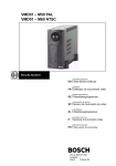
Figure 1 - The Mechatronic Demonstrator (Dirne, 2005)
The mechatronic demonstrator contains electronics and mechanics; a computer (PC/104) with an
external IO-board (with a digital to analog converter) and a mechanical slider on a rail. A belt is used
for the connection between motor and slider. The rail is connected via a special construction with two
springs to the fixed world. Due to this flexible frame, the demonstrator is assumed to behave like a
fourth order model which makes it interesting for educational purposes.
In 2003 the first mechatronic demonstrator was build by Controllab Products BV (Kleijn, 2003). Hans
Dirne builds a second demonstrator. More information about this mechatronic demonstrator is
reported by Dirne (2005). Figure 1 shows this demonstrator.
Control Engineering
2
End stops for the Mechatronic Demonstrator
Digital-Analog
Converter
Motor amplifier
Motor
(Maxon ADS 50/5)
(RE-35 118777)
Belt
Slider
(Sensoray 526)
Computer
End stops
(PC/104)
Digital
Input-Output
Position
sensors
Rotation
sensor
Figure 2 - Simple model of the demonstrator
1.2
Problem description
A hardware safety layer exists on the demonstrator. The safety layer prevents damage to the slider and
motor when someone makes a mistake or the controller becomes unstable. The safety layer of the
demonstrator consists of three switches: one emergency stop and two end stops mounted on the left
and right end of the rail. The three switches disable the motor supply so the motor is switched off.
+12 V
Left end stop
Right end stop
Emergency
switch
Motor Amplifier
Enable
Figure 3 – Electric schematic of the end stops in the old situation
In Figure 3 the schematic of the old electronic circuit is displayed. This safety layer is simple and the
functionality of the end stops is limited in this situation.
The problem can be divided in three sub problems:
University of Twente
Introduction
3
1. The slider does not stop in time. The slider moves to the end of the rail, the switch is activated,
but the slider bangs against the side and therefore sometimes the belt tears off, because the
disabling of the motor amplifier is not sufficiently to brake the motor.
2. The end stop responds independently to the slider direction. When the slider activates the end
stop, the motor power amplifier is disabled and so the controller cannot move the slider left or
right. So the slider must be moved to the middle of the rail by hand and the motor power
amplifier must be reset.
3. The computer does not know the start position of the slider at starting. The cause of this is that
the position sensor only measures the relative displacement and not an absolute position. The
computer needs to remember the place of the slider and have to calculate the position each
time again. Comparable to the second problem, the slider must be moved to the middle of the
rail by hand.
1.3
Objective
The objective of this individual design assignment is to solve the problems and to improve the
functionality of the end stops. Research has to be done to create an overview of the current and
alternative brake systems. Finally, the homing operation has to renewed, so the computer can initialize
the position of the slider.
Summarized, a demonstrator with improved safety layer has to be created, where it is not needed to
remove the plastic cover and to move the slider manually.
1.4
Requirements
The new safety layer has to satisfy several requirements. This section presents the requirements.
1.5
-
The safety layer has to stop the motor in case of an end switch or the emergency switch is
pressed.
-
The emergency stop should be fast enough so the demonstrator will not damage, or the safety
layer has to prevent such situations.
-
No need to move the slider manually in case of errors and for the homing operation. When this
is realized, there is no need to remove the plastic cover anymore.
-
The end stops are suitable to support the homing operation.
-
The power amplifier (Maxon Servo amplifier DES 50/5) should be kept, because it is a special
linear ‘current’ amplifier together with the digital-analog converter (Sensoray 526).
Outline of the report
In this chapter the mechatronic demonstrator is introduced. Some imperfections of the safety layer are
seen. And so the functionality of the end stops of the demonstrator has to improve.
Chapter 2 describes the analysis of the demonstrator. This analysis is necessary to get an overview of
the different parts of the demonstrator. A good knowledge of the hardware functionality is necessary
to identify the problems and limitations of the safety layer. After this analysis several alternatives are
given and discussed.
In chapter 3 the methods to improve the functionality of the end stops will be discussed. A new
hardware design is introduced and the used components are explained.
The implementation and measurements of the safety layer are discussed in chapter 4.
And last the conclusions and recommendations are discussed in chapter 5.
Control Engineering
5
2 Analysis of the functionality of the end stops
This chapter discusses the characteristics of the demonstrator and especially the end stop functionality.
This analysis is necessary to get an overview of the used hardware. The characteristics will be
analyzed to identify the problems and limitations. Several alternatives are discussed to get a realistic
solution.
2.1
2.1.1
Characterization of the demonstrator
Characterization of the motor brake
In the old situation, there is only passive braking of the motor. When an end stop is pushed, the motor
amplifier is switched off and that is all (see Figure 3). So the slider decelerates only by the friction of
the slider and motor.
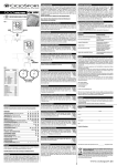
Next, the characteristics of the current motor without slider will follow. Three tests have been done to
measure the stop time with different brake methods to stop the motor. In all three test cases the
velocity of the motor is measured in revolutions per second as function of the time see Figure 4 and
Figure 5.
The motor has in these tests a constant velocity of 88rev/s at t = 0. The brake action starts each time at
t is 2 s. In the first test, the motor poles are short circuit; the motor voltage becomes 0V. In the other
two tests the motor amplifier is configured as a current source. The second test shows the motor
velocity with a switched set point from +1 to 0 Ampere (at t=2s). And in the last test the set point is
changed from +1 A to -1 A (at t = 2s).
model
90
w shortcut motor {rev/s}
70
50
30
10
-10
90
w open motor {rev/s}
70
50
30
10
-10
100
w changing direction motor {rev/s}
50
0
-50
-100
2
2.2
2.4
2.6
2.8
3
time {s}
Figure 4 – Measurement of the motor velocity by 1) Short circuit motor; motor voltage is changed to
0V; 2) Open circuit motor; motor set point is changed from 1A to 0A; 3) Changing motor direction;
motor set point is changed from +1 A to -1 A.
Control Engineering
6
End stops for the Mechatronic Demonstrator
Motor velocity
80
w shortcut motor {rev/s}
w open motor {rev/s}
w changing direction motor {rev/s}
60
40
20
0
2
2.01
2.02
2.03
2.04 2.05
time {s}
2.06
2.07
2.08
2.09
Figure 5 – Close up of the measurement of the motor velocity without slider by 1) Short circuit motor
terminals; 2) Open circuit motor terminals; 3) Changing motor direction
In the first test the motor velocity decreases exponentially. This exponential behavior can be
explained, because the motor voltage is regulated by the short circuit. The average deceleration of the
motor is approximately 2000 rev/s2. The measurement was done without slider, but when this data is
converted to translation, the slider should be decelerating 100 m/s2 average.
In test 2 and 3 the motor deceleration is constant. Deceleration of test 2 is approximately 88 rev/s2.
The slider decelerates theoretically 4 m/s2. In test 3 the deceleration is 1350 rev/s2 and the slider
deceleration is (theoretically): 66m/s2. So, the bigger the deceleration, the shorter the brake distances.
See Table 1 for a summary.
Test #
Description
Measured
Theoretical slider deceleration
Motor
deceleration
a = 2 ⋅ π ⋅ r ⋅ α [m / s 2 ]
α [rev/s2]
1.
Short circuit
2.
Set point change:
with: r = 7.76 ⋅ 10 −3 m
2000
100
88
4
1350
66
1A Æ 0A
3.
Set point change:
1A Æ -1A
Table 1 – Measurement results of the motor velocity by different motor brakes.
The start velocity of the motor is 88 rev/s in these measurements, this corresponds to a theoretical
slider velocity of 4 m/s, but the slider can not move with this velocity in practice. This measurement is
only been done to analyze the deceleration of the used motor with different voltage and current
changes.
2.1.2
Characterization of the motor control
The currently used motor amplifier is the Maxon ADS 50/5. This motor power amplifier of the
demonstrator can be configured in different ways: voltage-, current-, tacho- and encoder- control. The
University of Twente
Analysis of the functionality of the end stops
7
first two controllers use the internal voltage and current sensors to control the motor. The last two
configurations require an external tacho or encoder sensor.
The sensors of the demonstrator are only connected to the computer and not to the motor amplifier,
because the computer with sensors has to control the slider. So, only the voltage and current
configurations of the amplifier are interesting. The amplifier has no explicit braking function, but
when the amplifier is configured as a voltage source and the set point becomes 0 or negative, the
motor velocity will decrease fast. This is possible because the motor amplifier is a four quadrant
amplifier.
The current-torque relation is approximately linear (Maxon motor, datasheet) and therefore the power
amplifier of the motor is configured as current source. When the current source is disabled or similar
the set point becomes zero, the motor velocity will decrease linear and slowly (depending on its
friction). If the set point of the current source is not zero, the motor will decelerate or accelerate with
respect to the current. The maximum acceleration and deceleration are bounded by the current limiter.
Computer
(PC104)
-1…1
Digital-Analog
Converter
-10…10V
Motor amplifier
-1…1A
(Maxon ADS 50/5)
Motor
(RE-35 118777)
(Sensoray 526)
Figure 6 – Set point
The motor amplifier is controlled by the PC/104. This is the controller of the demonstrator. Because
the set point input of the motor amplifier requires an analog signal, therefore between the amplifier
and the PC/104 an analog-digital converter is present. The set point has a value between +10V and 10V this corresponds to a current of between +1 A and -1A. The current limiter of the motor amplifier
has been set to 1A.
2.1.3
Characterization of the homing
The position of the slider is needed for a correct homing operation. Therefore, the available position
sensors on the demonstrator have to be analyzed. There are three types of sensors: a linear strip with
detector, end stops and a rotation encoder on the motor.
The strip with detector on the demonstrator measures relative displacement. These sensors are
transmissive optical encoder modules. These are designed to detect linear relative displacement when
used together with a linear strip. The strip also has a marker which can be used as a reference.
The rotation encoder measures relatively angular displacement.
When the slider hits an end stop, its position is known, but the controller is currently unable to detect
the slider position or the end stop status.
2.2
Alternatives
This section discusses some alternatives to solve the problems, see section 1.2.
2.2.1
Motor brake alternatives
There are several possibilities to stop the motor. The analysis shows clearly that for slowing down the
slider the current must be changed of direction or the motor has to be short circuited.
First the options will be explained.
1. A different motor amplifier for example an H-bridge with brake functionality. In the current
configuration, the motor amplifier is configured as a current source. The current motor amplifier has
no brake function.
Control Engineering
8
End stops for the Mechatronic Demonstrator
Advantage
-
The new amplifier supports a brake
function
Disadvantage
-
Purchase costs of the new supply
-
Investment in the old motor supply is
wasted
-
20-sim models have to be changed
-
Current-Torque characteristic is less linear.
Simple solution
2. Using voltage control instead of current control. The motor brake is similar to short circuit the
motor.
Advantage
-
No extra hardware is required; the current
motor supply can be used.
Disadvantage
-
Difficult modeling, because there is no
linearity between voltage and torque. The
current-torque characteristic is
approximately linear and therefore it is
used in the current demonstrator.
An extra option by 2 is to change the current control into voltage control only then, when an end stop
is activated. So, no automation is possible, because the change of the configuration is made by
dipswitches.
3. Change the set point. In this option the set point is changed by extra hardware or software when an
end stop is active. The new set point value is negative to the old value and maximal so the motor stops
fast.
Advantage
-
The current motor supply can be used,
because this is a 4-quadrant motor control
Disadvantage
-
Feedback of the velocity of the motor is
required, because when the velocity of the
slider reaches 0 m/s, the set point must be
changed to 0A.
-
The maximum deceleration is proportional
to the current, but the current is limited by
the amplifier.
4. An extra circuit between the motor and the power supply. The function of this circuit is to short
circuit the motor when an end stop is active. There are several solutions of this circuit to short circuit.
Advantage
-
The analysis has shown that the
deceleration of the velocity is high.
-
The current motor supply can be used.
Disadvantage
-
Requires an extra circuit with development
costs and development time.
5. Mechanical brake. There are several solutions to stop the motor or the slider. For example fix some
bumpers on the demonstrator to catch the slider. Or mount a Maxon motor brake on the motor. These
options are extra; it can be implemented parallel to the electrical solution. And first the electrical
solution is chosen.
When the solutions are compared, a short circuit is the best option. Because the deceleration of the
motor is high and the current motor supply can be used in the same configuration (current-control).
And also the 20SIM models do not need to be changed.
University of Twente
Analysis of the functionality of the end stops
2.2.2
9
Short circuit alternatives
This section shows some alternatives to short circuit the motor. First the alternatives are described and
one of them is chosen. The alternatives are: Relay, Solid State Relay (SSR), Mosfet and TRIAC.
•
The relay is a simple method to short circuit the motor. The circuit is simple too, but there are
a few disadvantages. The switch time of a relay is not so fast and this mechanical switching
creates switch bouncing.
•
The solid state relay (SSR) is a fast electronic switch, which is based on transistor technology.
The lifetime of the ssr is higher then a relay, because that there are no moving parts, and thus
no mechanical wear.
•
A mosfet is a cheap and fast switching device. But the implementation is more difficult
compared to using a relay.
•
The TRIAC, or triode for alternating current, is a bidirectional electronic switch. The low
power type is used in many domestic appliances. Triacs are obtainable in different versions
and different power versions. It is also based on transistor technology and therefore fast
switching. Triacs are available for very high currents and voltages.
Here the possible solutions in a table are:
Alternatives
Relays
Advantage
Straightforward circuit
Conclusion
Disadvantage
Slow switching
+
Switch bouncing
Solid State
Relays
Straightforward circuit
Mosfet
Fast switching
Fast switching
Cheap
TRIAC
Fast switching
High current SSR is
not so cheap.
++
Difficult circuit and
implementation
+/+++
Cheap
High current and voltage
Straightforward circuit
Table 2 - Alternatives for the motor short circuit
The best and cheapest method to short circuit the motor is the TRIAC. The TRIAC can switch high
currents and there is no difficult development.
2.2.3
Direction sensor alternatives
A sub problem is that the motor amplifier becomes disabled independent of the movement direction of
the slider when it hits one of the end stops. It is desirable that the motor amplifier is enabled when the
set point changes in such way that the slider moves back. Some alternatives for direction sensors will
be described.
•
One solution is that the software driver converts the ‘analog signal’ to a digital signal which
contains the direction information and sends this calculated value to a digital output port.
•
The other solution is to use a voltage comparator. The detecting of the motor direction can be
measured by the set point. The set point has an analog value between -10…10V generated by
the digital to analog converter (Sensoray 526). A voltage comparator can translate this analog
voltage to a digital value.
The hardware solution is chosen, because in the case of a software crash the hardware can stop the
motor.
Control Engineering
10
End stops for the Mechatronic Demonstrator
2.2.4
Homing alternatives
For the homing problem, three alternatives are discussed:
•
An alternative is to change the position sensor strip for another strip which contains absolute
position indication. For this solution it is necessary to adjust the sensors and decoders. With
this solution a homing operation is no longer needed, because the controller always knows the
absolute position of the slider.
•
Connect the end stops to the PC/104. The current position strip contains a marker at a fixed
position. The controller can move the slider to the marker with the help of the end stops. So
the controller can calculate the position of the slider with the marker position or with the end
stop positions.
•
It is not per se necessary to connect the end stops to the computer. The computer can detect
the end stops with the position detectors and without the end stop status signals. With this
relative position information the computer can calculate the velocity and the acceleration.
These data together with the output current, give the end stop information. For example when
the slider is activating an end stop the velocity and the acceleration of the slider become zero.
The computer can detect an end stop when the set point of the current is not equal to 0 Ampere
and simultaneously the velocity is 0 m/s and the acceleration is 0 m/s2.
The last alternative is not so simple to implement in software, because double differentiation of the
position is required to calculate the acceleration. And digital differentiation needs filtering to remove
the noise. Furthermore the end stop information is not immediately available, because the deceleration
of the slider needs to be calculated.
The connection of the end stops to the pc is in any case a good idea and the position strip with marker
is already available on the demonstrator. So, the second solution is chosen. Therefore the end stops
have to be connected to the computer. The status of the end stop can then be used for the homing
operation.
2.3
Additional restrictions
This section analyzes some additional restrictions. The deceleration and velocity of the slider are
related. The faster the slider moves, the bigger the deceleration to keep constant the stop distance of
the slider. This section discusses these parameters. The used calculations are discussed in Appendix H.
2.3.1
Maximum deceleration
The deceleration and the force have a linear relation. The force is limited by the weakest link. For the
timing belt a maximal tension of 7 Newton is specified by the manufacturer. The manufacturer of the
rail has specified a maximal acceleration of 80 m/s2. This corresponds with a force of 9.52 N (The
mass of the slider is 119 gram).
So, the maximal brake force is limited by the timing belt (7 Newton). This corresponds to a maximal
deceleration of ~58m/s2.
2.3.2
Maximum current
The conversion of the voltage to the current of the power amplifier is established as 0.1 A/V (Dirne,
2005). This establishment is configured by the current limiter of the amplifier. Therefore, the current
of the motor amplifier is limited to 1 Ampere. So, the maximal acceleration or deceleration of the
slider controlled by the amplifier is theoretical 42 m/s2, Appendix H discusses this calculation.
2.3.3
Maximum velocity
The velocity has to be limited because the deceleration is limited. Some alternatives to limit the
velocity are discussed in Appendix A. This appendix discusses four possibilities to realize the velocity
limiting in hardware, but no hardware solution serve the purpose. Therefore in the final realizations of
University of Twente
Analysis of the functionality of the end stops
11
the PCB no velocity restriction is present. A recommendation is to implement a velocity limiter in the
controller software.
2.3.4
Maximum stop distance
The slider needs some distance to decelerate. The faster the deceleration gets the shorter the needed
stop distance. The maximal available distance between the end stop and the end of the rail is
approximately 3 cm. The slider length is also approximately 3cm. When the stop distance becomes
bigger the free space of the slider is proportionally smaller. Thus the slider has to stop within 3 cm
without touching the side.
2.4
Conclusion
From the analysis of the demonstrator, it has become clear that the end stops have to be improved.
When the slider activates an end stop, the slider does not brake, but only the motor power amplifier is
disabled. So, the deceleration of the slider is insufficient. Furthermore, it is necessary that the
maximum speed of the slider is not too high, because the deceleration is limited. A speed limitation
will not be implemented in hardware. Furthermore from the analysis, it has become clear that the
brake force of the motor is limited by the current limiter of the motor amplifier, because of this the
slider can not decelerate fast enough. Necessarily a brake function has to be implemented. The chosen
method is to use a TRIAC to short circuit the motor. Further to determine the direction of the slider, a
voltage comparator is chosen to convert the analog set point.
The methods of the chosen items are described in chapter 3.
Control Engineering
13
3 Method to improve the end stop functionality
This chapter discusses the methods to improve the end stop functionality and how these can be
realized. First, the different methods are discussed. Further a block diagram is introduced to make the
different parts understandable. At the end of this chapter a final electric schematic for every part is
discussed.
3.1
3.1.1
Chosen methods
Brake method
This section describes the brake method. The main component to brake the motor is the TRIAC. This
component is chosen in the previous chapter. The TRIAC, or TRIode for Alternating Current is an
electronic component and exists of N- and P-material, just like a transistor, but with an different
structure. The TRIAC is a bidirectional electronic switch which can conduct current in either direction
when it is enabled. It is enabled by a voltage, which is applied to its gate electrode. The used TRIAC is
displayed in Figure 7.
Figure 7 – TRIAC; BTA08-600BRG TO-220AB
The chosen type is the Triac BTA08-600BRG, this is an 8A 600V TRIAC, with a current peak of 80A.
It is chosen arbitrary; however the current and voltage of this type are enough.
3.1.2
Direction dependency method
The chosen method for the direction problem is to use a voltage comparator to get the direction
information from the set point. The comparator converts the analog value of the set point into a digital
value (1 or 0). This value corresponds to the direction of the slider (left or right). So, the voltage
comparator seems to be a Sign function. The voltage comparator should have a high impedance input,
so the Sensoray 526 (DAC) is not overloaded. The Sensoray has an analog output with a range of 10…10V and 2mA output. The chosen voltage comparator is the LM311.
3.1.3
Homing method
The homing operation initializes the controller with the absolute position information of the slider. It is
a moving operation of the slider to a reference point. The reference point consists of a marker on the
linear encoder strip. The detector detects the marker and gives feedback to the controller. The marker
has the same precision as the resolution of the linear strip and the position sensor: 40,000 ticks/m this
means an accuracy of 25μm.
The implementation of the homing is simple; a move action to the left end stop and a move action to
the right to detect the marker or to calculate the center.
Control Engineering
14
End stops for the Mechatronic Demonstrator
Start Homing
Move left
yes
Detect
Marker?
yes
no
Detect Left
End stop?
no
Move right
yes
Position0 = Marker
Detect
Marker?
yes
no
Detect Left
End stop?
no
Offset =½(right – left)+left
Position0 = position - offset
Move center
The homing has finished
The slider is at Position0
Figure 8 – Homing operation
The offset of the marker to the middle of the rail can be calculated to initialize the position at 0 when
the slider is in the middle between the end stops.
3.2
Block diagram
Figure 9 shows a block diagram of the wanted end switch implementation. Two parts of the block
diagram are obviously the motor and the power amplifier. The motor amplifier is the current source for
the motor.
Further the block diagram contains a short circuit block. This short circuit block is inserted to connect
the two terminals of the motor together with a low resistant conductor when the motor amplifier is
disabled. So when an end stop is activated, the amplifier has to be disabled and the motor has to be
short circuit.
The brake function of the slider has to be direction dependent. This means that the slider has to be
brake if and only if the end stop is activated and the slider moves in the wrong direction (in the
direction of the end of the rail). The enable signal has to be a function of the direction of the slider.
University of Twente
Method to improve the end stop functionality
15
The objective is that the motor only brakes when an end stop is touched and the orientation of the set
point is ‘wrong’. When the set point orientation is ‘good’, the slider has not to be brake even if the end
stop is touched, so the slider can leave the end stop. This part in the block diagram has the following
inputs: the two end stops and the direction information from the set point, the output is the enable
signal for the motor brake.
This block diagram contains a logic block, a direction detector block and a motor brake block.
Motor set point
Enable Motor Amplifier
Sign function
End stop 1
End stop 2
Emergency stop
Logic function
block
M
Short circuit
Computer
Figure 9 - Block diagram of the hardware safety layer
3.3
Electric circuits
This section explains the electric circuits that implement the functionality from Figure 9. See
Appendix C for all schematics and see Appendix B for more information about the configuration of
the hardware connectors.
3.3.1
Electric circuit of the motor brake
The TRIAC needs some other components to function properly. This section explains the schematics.
R1
MOTOR
MAXON RE-35 118777
R2
Maxon Motor
Amplifier
+
A
BTA08-600BRG
TRIAC DRIVER
K3010P3
+Motor
-Motor
Triac
C1
L1
CHOKE
Figure 10 - Triac circuit
Figure 10 shows the electric motor brake circuit with the TRIAC. The TRIAC is controlled by a
TRIAC driver. The TRIAC driver provides an optic isolation between the digital electronics and the
TRIAC. The resistor R1 and the capacitor C1 build a snubber network. A snubber network is a resistor
Control Engineering
16
End stops for the Mechatronic Demonstrator
and capacitor in series and is placed in parallel with the output of the TRIAC. The snubber network is
needed because the motor causes noise. The resistor R2 regulates and limits the current into the gate.
The TRIAC can short circuit the motor fast and independently of the motor polarity.
A choke is added to the motor circuit, according to the datasheet of the Maxon motor amplifier
(Maxon motor amplifier, datasheet) an extra choke is necessary if the DC-motor has a terminal
inductance lower than 0.35mH. The currently used motor has a terminal inductance of 0.34mH. A
choke of 120μH is added. A choke is added instead of an inductor, because an inductor stores energy
and the choke dissipates energy for higher frequencies.
3.3.2
Electric circuit of the direction dependency
This section discusses the electric circuits concerning the direction dependency. Three schematics are
shown: the voltage comparator, the power supply schematic and the logic schematic.
V+
VCC
R2
R3
MotorEnable
ISO1
2N37
V+
+SetValue
U1
LM311
C1
100pF
Logic
block
+
-
-SetValue
R1
Inputs
V-
Figure 11 – Motor direction detector. The voltage comparator converts the analog voltage to a digital
signal.
In Figure 11 the voltage comparator is shown. Dependent on the set point the output voltage is high or
low. The optocoupler is added for galvanic isolation between the output and the motor amplifier. The
right side of the optocoupler is connected to the motor amplifier together with its power and ground. In
the schematic different symbols are used.
The comparator needs a positive and a negative power supply which have to be higher than its input
range. The necessary voltages for this comparator are generated by a DCDC-converter. The chosen
DCDC-converter is the IA0512S; it generates +12V and -12V from the 5V. A DCDC-converter is
needed because only 5V is available on the print. The V+ and V- in the schematic are generated by the
DCDC-converter.
V+
VCC
U2
1
Vin
+V
0V
2
GND
IA0512S
-V
+
C4
25u
+
C6
25u
6
C5
100n
5
4
C7
100n
V-
Figure 12 – DCDC-converter. It creates a +12V and -12V for the voltage comparator.
University of Twente
Method to improve the end stop functionality
17
In Figure 12 the electric schematic of the DCDC-converter is shown.
Further, logic components are needed to create a function of the inputs to get the desired output. The
inputs exist of two end stops, the emergency stop and the motor direction signal. The function can
simply been written:
MotorBrake = EndStopLeft ⋅ Direction + EndStopRight ⋅ Direction + EmergencyStop
There are several solutions to implement this function in hardware. One possibility is to use
programmable logic, but the function is small and fixed. So, another method is chosen using standard
gates. The function can be implemented with one Nand-IC and one Not-IC.
The components are:
Nand-gate 7400;
Not-gate: 7414.
The function of the logic is to give a brake signal dependent on the inputs: the end stops and the motor
direction. The logic is fast enough, so the reaction time is not a bottleneck.
U6E
U6A
Motor direction
11
10
1
2
Enable Motor
7414
7414
Endstop Lef t
U4A
1
3
Emergency stop
12
U6B
2
U4C
U4D
9
7400
U6C
11
8
3
4
6 Motor brake
5
13
10
U4B
7400
4
7400
Endstop Right
7414
7414
6
5
7400
Figure 13 - Logic circuit
Figure 13 shows the realized circuit with a NAND and NOT gate. The end stops and the emergency
switch are switches that are connected in normally closed mode. This means that the functionality of a
not connected switch equals a presses switch.
Some LEDs are added to the schematic for extra functionality. Two LEDs show the status of the
switch and two other LEDs, red and green, indicate the motor direction. Furthermore, these LEDs
indicate if the print is active and the power is turned on.
3.3.3
Electric circuit of the end stops
A debounce circuit is added between the end switches and the computer. The emergency stop and the
two end stops are connected to the computer. More precisely, the switches are connected to the digital
IO connector of the Sensoray IO-board. The debounce circuit is added to remove the contact bounce
because contact bounce is a problem of mechanical switches.
VCC
VCC
R8
10K
R9
10K
U3A
74HCT00
EndStopLef t_1
EndStopLef t_2
1
3
2
DIO4
4
6
5
U3B
74HCT00
EndStopLef t
Figure 14 – Debounce circuit for the end stops
Control Engineering
18
End stops for the Mechatronic Demonstrator
In Figure 14 the debounce circuit is shown. The end stop is connected to DIO-4 (this is a digital input
output pin number) of the Sensoray board. The complete configuration of the connectors is described
in Appendix F.
3.3.4
Electric circuit of the initialization
In the circuit with the start and emergency stop, a D-flip-flop is added to hold the enable signal. The
start and emergency are respectively the set and reset. The resistor and capacitor create a reset on
startup, because when the main power to the demonstrator is turned on, the amplifier and the motor
have to be disabled to prevent unwanted movements.
VCC
VCC
R12
10K
Enable Motor
D
Start
Q
Q
CLK
R13
10K
C1
VCC
1
Emergency
2
CLR
PRE
U4A
7474
R1
U5A
74HCT14
Figure 15 - Initialization circuit
3.4
Conclusion
In this chapter the chosen methods to improve the mechatronic demonstrator are described. These
methods are used to realize the new functionality of the end stops. First the method to create an active
motor brake with a TRIAC is discussed. Further the method to realize direction dependency of the
slider is discussed and last the end stops connection to the IO-board of the computer is discussed. All
method descriptions are equipped with the electric schematics. The next chapter handles the
implementation and realization of these methods.
University of Twente
19
4 Realization and testing
This chapter discusses the realization and testing of the new functionality of the end stops. First a short
preparation of the implementation is discussed. Then the realization is discussed. Furthermore the test
cases of the test procedure are described and the results are shown. Finally, the validation of the results
with the objective is done.
4.1
Preparation
Before the rest of this chapter, a short preparation is described of the first trail run. The printed circuit
board is created and the connectors have to be connected. The left and right end stop can be mistaken,
but this is depending to the connected + and – poles of the set point. It is recommend to remove the
slider in the first trail run and to check if the polarity of the set point is matching with the two
connected end stops.
After the right installation the end stops appeared to work properly. Take care of the timing belt,
because in the case of an extremely braking force of the motor, the teeth of the belt are destroyed. So,
it is recommended that a stronger timing belt is used and also replace the pulleys into bearing ones to
pre-tension of the timing belt.
4.2
Realization
For a stable and robust realization of the hardware safety layer, the final circuit is made on a printed
circuit board. The different circuits, described in chapter 3, are created on a single print. The specific
information about the printed circuit board is discussed in the appendixes.
4.2.1
Power supply
The required voltage of the print is 5 Volt. The print uses approximately 100mA and so simply the 5V
computer supply that is present on the demonstrator is used.
4.2.2
Printed circuit board details
All schematics of the electric circuits that are made are added in Appendix C – Printed circuit board
schematics. The next appendix shows visually the connections between the PCB and the mechatronic
demonstrator. See Appendix D – Printed Circuit Board Configuration.
For a detailed description of the used components and the used connectors, the next two appendices
are added. Appendix E – Part list printed circuit board, this appendix presents the tables with the
resistors, capacitors and other used components. And Appendix F – Connectors user manual explains
the connectors of the PCB. The pin layout of each connector is described.
4.3
Test procedure
This section describes the functional tests cases of the PCB. The results of these test cases are
described in section 4.4.
4.3.1
Motor brake test
Simple motor brake test
Action
Start the slider with a constant
velocity of 0.5 m/s.
The slider activates a switch.
Expected result
• The slider moves with a velocity of 0.5 m/s.
•
•
The motor amplifier is disabled.
The slider brakes.
Deceleration of the slider
In this test case the deceleration of the slider for different slider velocities will be measured. 20SIM is
used to steer the motor to move the slider with a defined velocity as far as the end stop and measure
the velocity of the slider during this experiment. Further calculate the deceleration of these velocities.
Control Engineering
20
End stops for the Mechatronic Demonstrator
Action
Move the slider with a velocity vn to
the switch.
vn ={0.3 … 1.5} m/s step 0.1 m/s
Expected result
• The switch is activated and the slider stops.
•
4.3.2
Measurement results are available to plot graphs.
Slider direction test
Left end stop
In this test the direction dependency of the slider is tested. When the direction of the set point has
changed from left to right or reverse, while the slider is pressing an end stop, the motor amplifier is not
more disabled. So, the slider can leave the switch.
Check the functionality of the direction LEDs on the PCB.
Precondition
The slider is pressing the left end
stop.
Action
Expected result
Change the set point slowly from:
• The slider moves to the right side.
(left) to 0 to (right).
• The direction LED ‘left’ is turned off and the
LED ‘right’ is turned on.
Stop the test
•
Right end stop
Repeat the previous test for the right end stop.
4.3.3 Slider homing test
In this test the following aspects are measured:
- The status information of the right end stop is available on the controller.
- The status information of the left end stop is available on the controller.
The PC/104 controls the movement of the slider.
Action
Expected result
Move the slider to the left.
• The slider moves to left.
• The slider activates the left end stop.
• The status information of the left end stop has
changed to “active” on the controller.
• The left position of the slider is saved.
Move the slider to the right.
• The slider moves right.
• The slider activates the right end stop.
• The status information of the right end stop is
available on the controller.
• The controller calculates the distance between the
end stops.
Move the slider to the center
• Calculate the center of the rail.
• Move the slider to the center.
Optional
The position detector detects the
• The slider uses the fixed marker as reference.
marker in one of above sequences.
• The slider moves to the marker.
4.3.4
Other tests
Power consumption
Action
Connect the PCB to a 5 V power
supply together with a current meter.
Expected result
• The PCB is ready and one direction LED is on.
University of Twente
Realization and testing
Measure the current consumption of
the PCB.
21
•
The current is 100 mA or less.
Status LED “Server Online”
Test the “Server Online” LED.
Action
Switch on the “Server Online” LED.
Switch off the “Server Online” LED.
Expected result
• The “Server Online” LED is on.
• The “Server Online” LED is off.
Status LED “Model Started”
Test the “Model Started” LED.
Action
Switch on the “Model Started” LED.
Switch off the “Model Started” LED.
Expected result
• The “Model Started” LED is on.
• The “Model Started” LED is off.
Status amplifier enabled
Action
Press the start button
Press the emergency button
Start the demonstrator
Action
Switch on the power of the
demonstrator.
Press the start button.
4.4
Expected result
• The amplifier is enabled.
• This status information is available in 20Sim
controller.
• The amplifier is disabled.
• This status information is available in 20Sim
controller.
Expected result
• The PCB set the amplifier in disable mode.
•
The amplifier is enabled.
Results
This section discusses some measurements of the final print. The different test cases in the previous
section have to be executed and the measurements have to be shown.
4.4.1
Increasing deceleration
In the first test the stop distance of the slider was measured with different velocities. This
measurement data is shown in Figure 16 and Figure 17.
Control Engineering
22
End stops for the Mechatronic Demonstrator
Braking velocity
Velocity vt1 = 1.7 m/s
Velocity vt1 = 1.6 m/s
Velocity vt1 = 1.5 m/s
Velocity vt1 = 1.3 m/s
Velocity vt1 = 1.1 m/s
Velocity vt1 = 0.9 m/s
Velocity vt1 = 0.7 m/s
Velocity vt1 = 0.4 m/s
1.6
1.4
1.2
1
0.8
0.6
0.4
0.2
0
1.02
1
1.04
1.06
time {s}
1.08
1.1
Figure 16 – Braking velocities v(t) {m/s}. Different velocities are measured, when the end stop is
pushed at t =1s the slider brakes and the velocity decreases to zero.
Braking distance at different velocities
0.135
0.13
0.125
0.12
Distance {m} vt1 = 1.7 m/s
Distance {m} vt1 = 1.6 m/s
Distance {m} vt1 = 1.5 m/s
Distance {m} vt1 = 1.3 m/s
Distance {m} vt1 = 1.1 m/s
Distance {m} vt1 = 0.9 m/s
Distance {m} vt1 = 0.7 m/s
Distance {m} vt1 = 0.4 m/s
0.115
0.11
0.105
1
1.02
1.04
1.06
time {s}
1.08
1.1
Figure 17 – Braking distances x(t) {meter}. The position of the slider is measured with different
velocities and the end stop is located at position x= 0.105m. The matching velocities are shown in
Figure 16.
University of Twente
Realization and testing
23
In Figure 16 the stop distance of the slider is shown. The stop distance is longer, when the velocity is
higher.
When the slider moves more than 3cm, the switch is passed, because the size of the slider is 3cm. So,
the velocity of the slider has to be limited at maximal 1.5m/s. The force of the motor is passed on the
slider by the belt. In Figure 17 the different braking distances are shown for the specific test velocities.
The end stop is pushed at t=1s. The velocities do not decrease linear, because the brake force is not
constant, because the matching current is not constant, but dependent on the decreasing voltage of the
motor.
Test #
Start velocity v {m/s}
Braking distance
{cm}
Average deceleration
{m/s2}
a=
1 v2
2 s
1
1.7
3.1
47
2
1.6
3.0
43
3
1.5
2.8
40
4
1.3
2.7
31
5
1.1
2.5
24
6
0.9
2.2
18
7
0.7
1.8
14
8
0.4
1.7
5
Table 3 – Measurement results of the braking test
Table 3 shows a survey of the measurement results. It is clear that the braking distance gets bigger
when the velocity gets higher. Also the average deceleration gets higher, but the stop distance is not
smaller or stays constant, but de distance becomes longer. The deceleration of test 8: 5 m/s2 is
approximately equal to 4 m/s2 which is the measured deceleration of section 2.1.1 with no braking
functionality. So, with low slider velocities the short circuit does not increase the deceleration.
The short circuit method works, but insufficient. When an end stop is activated, the motor is short
circuit and it stops. But the stop distance of the slider is dependently on the velocity. When the
velocity is too high, the slider bangs to the side. Therefore the velocity has to be limited. So, a velocity
limiter is recommended.
4.4.2
Direction dependency
The motor amplifier is disabled only dependently on the slider direction in combination with an end
stop. When an end stop is activated the motor supply is disabled, but when the set point is changed, the
motor direction becomes negative to the previous direction (previous set point), and then the motor
supply is enabled and the slider can leave the end stop. So the software has to change the set point and
is be able to drive the slider. In the next section it is shown that the direction dependency works
properly.
4.4.3
End stop connection to the computer
The end stops are connected to the computer. So, it is possible to check the state of the end stops and
do a homing operation.
In 20SIM a simple homing operation with end stops is added to an existing 20SIM model.
Control Engineering
24
End stops for the Mechatronic Demonstrator
Advanced_Controller
A
Advanced_Controller
StartStop
K
V
A2V
D
V
A
A
K
DA1
Amplifier
K
N
Motor
frame
motortraagheid
m
wereld
frameflex
F
m
motor
P
m
motorflex
last
damper
motorsensor
lastsensorframe
P
lastsensorwereld
P
ticks
A
K
controller
counter
m
D
plant
AD1
A
EndStopSimulator
D
AD2
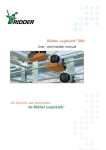
Figure 18 – 20SIM model of the Mechatronic Demonstrator with homing functionality
In Figure 18 the 20SIM model is shown. The EndStopSimulator sub model and the
AdvancedController are added.
EndStop1
EndStop2
StartStop
position1
position2
State
StateMachine
HomingOffset
K
Homing
Ticks2meter_2
position3
K
NormalOperation
Ticks2meter
output
SignalLimiter4
Figure 19 – Advanced Controller sub model
The advanced controller exists of a normal operation controller and a homing controller. The state
machine has five different states:
State 0: The initial state waits until the start button is pressed while the emergency button is not
pressed. Then go to state 1.
State 1: The homing operation is started and the slider moves to left until the left end stop is activated.
This slider position is saved and then go to state 2.
State 2: The slider moves right until the right end stop is activated. This slider position is also saved.
The next state is state 3.
State 3: The slider moves to home: The slider calculates the center with the left and right position
values and the slider moves to this position.
State 4: The slider starts the normal operation.
University of Twente
Realization and testing
25
model
4
State
2
0
Position {ticks}
10000
5000
0
-5000
1.5
EndStop1
1
0.5
0
1.5
EndStop2
1
0.5
0
0
5
10
time {s}
15
20
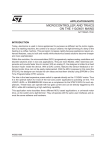
Figure 20 – Measurement results of the 20SIM model with homing functionality
Figure 20 shows some measurement values. The slider moves and activates the end stops. The end
stops change the active state of the state machine. After the homing operation, the slider moves
according to a block wave pattern which is controlled by the normal operation controller. In this
simulation the slider does not start in the middle of the rail, so the homing operation creates an offset
value. In Figure 19 the offset signal is subtracted of the slider position, so the controller moves the
slider with a block pattern round the middle.
4.5
Conclusion
This section evaluates the improved functionality and if the problems are been solved sufficiently and
if there are still possible restrictions. In section 1.2 the three imperfections of the end stops are
discussed.
4.5.1
Motor brake functionality
The first problem is that the slider does not brake when an end stop is pushed. Because of this, damage
can occur. The old electric circuit with the end stops does not brake the motor active. The solution is a
new electric circuit that brakes the motor actively. This is realised with a TRIAC which is short
circuited the motor.
The deceleration of the slider is increased from 4 m/s2 to 40 m/s2. Because of this increased
deceleration, the stop distance gets shorter, but the real stop distance is determined by the velocity of
the slider. When the slider velocity is below 1.5 m/s, the stop distance should be acceptable
(approximately 3cm). So a slider velocity limiter is recommended.
Further, it is recommend to replace the timing belt for a stronger one, because this one has reached the
boundaries of its specification when the motor brakes with maximum power.
4.5.2
Direction dependency functionality
The second problem is the direction dependency of the end stops. This function is not implemented in
the old end stop realization. In the old situation the power amplifier is disabled independently to the
slider direction. When an end stop is activated the power amplifier is always disabled. The controller
cannot enable the amplifier and also it cannot be enabled with a slider direction change.
Control Engineering
26
End stops for the Mechatronic Demonstrator
To solve this problem a slider direction dependency motor brake is implemented. The electrical circuit
contains logic to enable the motor amplifier when the set point is changed. This implementation is
discussed in the previous chapter. With this implementation the problem is solved.
4.5.3
Homing functionality
The homing functionality of slider is the last problem. The start position of the slider was not defined.
The position sensors of the slider detect only the relative position.
This problem is solved by a homing operation on start up of the controller. The end stops are
connected to the controller. The controller uses the end stop status to do the homing operation. With
this solution the last problem is solved.
University of Twente
27
5 Conclusions and Recommendations
5.1
Conclusions
This individual design assignment has resulted in an improved hardware safety layer. The end stops
have more functionality and improve the safety of the Mechatronic Demonstrator.
•
The motor brake is improved with a TRIAC. The TRIAC short circuits the motor to decelerate
faster instead of the previous disabling of the motor amplifier. Thus, the motor stops faster.
The deceleration of the slider is now maximal 40 m/s2 instead of 4 m/s2.
•
The end switches are now direction dependent, allowing the slider always to move away from
the end switch.
•
The end stops are connected to the computer (PC/104). With this end stop information a
homing operation is added.
These new functionality is implemented on a printed circuit board. This bachelor assignment has
resulted in an increased end stop functionality of the mechatronic demonstrator.
5.2
Recommendation
This section discusses some recommendations for further research.
•
A software safety layer is recommended. This software prevents that the slider does not touch
the end stops and so, it improves the solutions of the problems 1 and 2 of session 1.2.
•
Implement a slider velocity limiter is software. The slider velocity has to limit to
approximately 1.5 m/s.
•
Implement the detection of the marker in the homing operation, because this detection is
currently not implemented in the homing operation. Furthermore, examine the efficiency of
the homing speed.
•
Change the current timing belt for a stronger one, and replace the pulleys for bearing pulleys
to pre-tension the belt.
Control Engineering
28
End stops for the Mechatronic Demonstrator
Appendix A – Limiting motor velocity
In the safety layer for the demonstrator the motor velocity has to be limited. The velocity of the slider
has to be limited to a maximum because the deceleration and the stop distance are not infinity. The
velocity of the slider has to be limited to approximately 1 m/s. This limiting process can be done in
hardware and software. This appendix discusses some hardware trials. The software solutions shall not
be discussed in this report.
Four hardware solutions shall be explained:
1. A different power supply for the motor amplifier;
2. Voltage reduction of the motor;
3. Feedback of the (differentiated) motor position sensor to the motor brake;
4. Feedback of a motor voltage to the motor brake.
First, the effects of the voltage decreasing of the motor have to be discussed. The motor velocity is
dependent of the motor voltage in accordance with formula:
u=KΦω
Further, the motor amplifier is used as current source, so the Torque is controlled.
T=KΦi
Also the acceleration α is controlled because:
T = I α (Torque and acceleration are proportional, with constant inertia)
So the motor torque and acceleration can be controlled by the current. But the maximum velocity is
depended of the motor voltage.
A.1.
Different power supply
Different power supplies can be used for the motor amplifier. The Maxon motor amplifier has a width
input power supply range of 12 – 50 VDC. The voltage of the current power supply is 21.5 V and the
maximum velocity of the motor is 88rev/s. But if the minimum voltage is used, then the motor
velocity is 47rev/s by 12V. But the slider is still moving to hard.
A.2.
Voltage reduction
In this experiment the voltage over the motor is reduced. The voltage must be reduced by a component
that only reduced the voltage and not the current, so the torque and acceleration are not changed.
D1
DIODE
R1
Q1
1
R2
1
+
BATTERY
A
+
2
-
BATTERY
A
MOTOR SERVO
2
-
Figure 21 – Voltage of the motor is simply
reduced by a diode
MOTOR SERVO
Figure 22 – Voltage of the motor is reduced by a
power transistor which is simply configured by
the resistors
University of Twente
Appendices
29
The simplest method is to add a diode to the circuit. In Figure 21 the voltage of the motor is 0.6V
lower than the battery. And in Figure 22 the voltage of the motor is reduced by:
v0 =
0.6V
⋅ (R1 + R2 )
R2
vmotor = vbattery – v0
The circuit of Figure 22 is tested in practice. The voltage of the PWM is reduced to 6.5V instead of
21.5V. Some results are shown in Figure 23.
Motor velocity, Current set point = 0.5A
100
Motor velocity, Current set point = 0.5A
90
25
80
70
20
60
w {rev/s} V= 21.5V
w {rev/s} V= 6.5V
50
15
w {rev/s} V= 21.5V
w {rev/s} V= 6.5V
40
10
30
20
5
10
0
2
2.5
3
3.5
time {s}
4
4.5
5
a
600
Motor acceleration, Current set point = 0.5A
a {rev/s2} V= 21.5V
a {rev/s2} V= 6.5V
500
400
300
0
1.8
1.9
2
2.1
2.2 2.3
time {s}
2.4
2.5
b
Figure 23 – Measurement results of reducing of
the motor voltage. In figure a) is shown the motor
velocity with set point 0.5A. The red one is
created with the normal PWM voltage of 21.5V
and the black one is created with a reduced
voltage of 6.5V. Figure b) is a close-up of a).
Figure c) shows the motor acceleration. The
maximum of red is approximately 550rev/s and
the black one 500rev/s.
200
100
0
2
2.5
3
3.5
4
time {s}
4.5
5
c
The conclusion of this test is that it is possible to decrease the maximum motor velocity when the
voltage is decreased. But the acceleration is not constant between 0 – 25rev/s. The acceleration
decreases dependently of the motor voltage and this is not desirable. In general the motor acceleration
is not constant in the last 20rev/s so the last increase of 5V can not be used.
This method is not desirable to limit the velocity of the slider, because the acceleration is not constant
in the used range, so the limiter does not work adequate.
Control Engineering
30
End stops for the Mechatronic Demonstrator
A.3.
Feedback of the motor velocity
Solution 3 contains a feedback of the motor velocity to the motor brake. This is not easy to implement
in hardware because the motor position sensor has to be differentiated, because the velocity is not
measured. It is easier to implement this feedback in software.
A.4.
Feedback of the motor voltage
Solution 4 contains a feedback of the motor voltage to the motor brake, because the motor voltage is
proportional to the motor velocity. The PWM voltage of the motor has to be transformed to an
effective voltage. Another method is to use the “monitor n”-output of the Maxon amplifier, but the
amplifier is configured as current control. It is not so simple to implement a voltage feedback. This
report shall not discuss this development or implementation.
University of Twente
Appendices
31
Appendix B – Hardware connector configuration
This appendix contains the configuration of the hardware connector for the mechatronic demonstrator.
B.1.
Input
Device 0: Sensoray 526
Type: Encoder
Channel 0: Motor angle
{2000 ticks/revolution}
Channel 1: Slider position 1 (World)
{40,000 ticks/m}
Channel 2: Slider position 2 (Top)
{40,000 ticks/m}
Channel 3: Slider position 3 (Bottom)
{40,000 ticks/m}
Type: Digital In
Channel 0: End stop 1
Channel 1: End stop 2
Channel 2: Status of Start/Emergency stop
Channel 3: NC
B.2.
Output
Device 0: Sensoray 526
Type: DAC (digital analog converter)
Channel 0: Set point motor
Channel 1: NC
Channel 2: NC
Channel 3: NC
Type: Digital Out
Channel 0: LED Server Online
Channel 1: LED Model Started
Channel 2: NC
Channel 3: NC
Control Engineering
1
2
J6
HEADER 4
1
2
1
2
3
4
J5
HEADER 4
J9
HEADER 2
1
2
3
4
R2
1K
R1
1K
SW2
SW KEY-SPDT
VCC
VCC
SW1
SW KEY -SPDT
+
C1
35u
VCC
C2
100n
EndStop
EndStopLef t_1
EndStopLef t_2
EndStopRight_1
EndStopRight_2
EndStop
Direction
-SetValue
+SetValue
Direction
DIO6
DIO5
DIO4
PC3_Emergency
EndStopLef t
EndStopRight
MotorDirection
2
4
6
8
10
MotorControl
1
3
5
7
9
J7
HEADER 5X2
PC3_Emergency
EndStopLef t
EndStopRight
Emergency Stop
Start
MotorDirection
MotorControl
-MOTOR
+MOTOR
-MOTOR_AMP
+MOTOR_AMP
EnableMotor
R4
R
R3
R
1
2
1
2
1
2
1
2
HEADER 5
J10
HEADER 2
J8
HEADER 2
J4
HEADER 2
J3
HEADER 2
C.1.
HEADER 2
J2
0
Vopto
1
2
3
4
5
J1
32
End stops for the Mechatronic Demonstrator
Appendix C – Printed circuit board schematics
Main schematic
Figure 24 – Main schematic
University of Twente
EndStopRight
EndStopLef t
MotorDirection
Emergency Stop
Start
3
4
U5B
74HCT14
VCC
5
D1
LED RED
R18
1K
U5C
74HCT14
6
R14
100K
R13
10K
VCC
1
U5A
74HCT14
13
12
2
1
U6D
74HCT00
U6A
74HCT00
D2
LED GREEN
R19
1K
C9
220n
2
11
3
5
4
VCC
U6B
74HCT00
1
4
3
2
U4A
7474
CLR
PRE
CLK
D
6
Q
Q
5
6
9
U5D
74HCT14
8
9
10
U6C
74HCT00
8
11
U5E
74HCT14
10
VCC
R16
R
2
1
6
4
R12
10K
VCC
R20
1K
VCC
Q1
TRIAC DRIVER
R17
R
0
R21
12K
ISO2
2N37
Vopto
C10
100nF
R15
2K2
1
Control Engineering
2
Figure 25 – Schematic of the logic and the short circuit of the motor
5
Q2
TRIAC
220uH/5A
L1
EnableMotor
-MOTOR_AMP
-MOTOR
+MOTOR
+MOTOR_AMP
PC3_Emergency
C.2.
4
VCC
Appendices
33
Motor control schematic
34
End stops for the Mechatronic Demonstrator
C.3.
Direction schematic
V+
8 5
+SetValue
U1
LM311
C3
100pF
-SetValue
2
+
3
-
7
4 1 6
R7
560K
V-
Figure 26 – Motor direction detector. The voltage comparator converts the analog voltage to a digital
voltage.
V+
VCC
U2
1
Vin
+V
0V
2
GND
IA0512S
-V
+
C4
25u
+
C6
25u
6
C5
100n
5
4
C7
100n
V-
Figure 27 – DCDC-converter. It creates a +12V and -12V for the voltage comparator.
University of Twente
Appendices
C.4.
35
End stop schematic
VCC
VCC
R8
10K
R9
10K
U3A
74HCT00
1
EndStopLef t_1
3
2
EndStopLef t_2
DIO4
4
6
5
U3B
74HCT00
EndStopLef t
VCC
VCC
R10
10K
R11
10K
U3C
74HCT00
EndStopRight_1
EndStopRight_2
9
8
10
DIO5
12
11
13
U3D
74HCT00
EndStopRight
PC3_Emergency
Figure 28 – Debounce circuits for the end stops
Control Engineering
DIO6
36
End stops for the Mechatronic Demonstrator
C.5.
Remaining circuits
VCC
12
VCC
C11
100n
C12
100n
C13
100n
Figure 29 – Uncoupled capacitors
13
12
11
13
10
C8
100n
U5F
74HCT14
Figure 30 – The input
of the not used inverter
is grounded
D
Q
Q
9
8
CLK
CLR
PRE
U4B
7474
Figure 31 – The inputs of
the not used D-flipflop are
grounded
University of Twente
Appendices
37
Appendix D – Printed Circuit Board Configuration
D.1.
Connections overview
GND
Vcc +5V
SENSORAY
Digital J5
Analog J3
Figure 32 – Connections overview of the PCB
Control Engineering
38
End stops for the Mechatronic Demonstrator
Appendix E – Part list printed circuit board
This appendix contains tables with components which are used on the PCB.
E.1.
Resistors
Resistor
Value
Description
R1
50
Resistor for LED by end stop 1
R2
50
Resistor for LED by end stop 2
R3
550
Resistor for LED Server Online
R4
550
Resistor for LED Model Started
R5
2k2
LED of optocoupler
R6
5k
Transistor of Optocoupler
R7
560k
Input voltage comparator
R8
10k
Pull up resistor end stop 1
R9
10k
Pull up resistor end stop 1
R10
10k
Pull up resistor end stop 2
R11
10k
Pull up resistor end stop 2
R12
10k
Pull up resistor start button
R13
10k
Pull up resistor emergency button
R14
1k
RC-Delay for reset by start up
R15
10
Snubber network
R16
270
LED of TRIAC driver
R17
10
Triac driver
R18
200
LED red motor direction
R19
200
LED green motor direction
R20
1k
LED Optocoupler Enabling amp.
R21
12k
Transistor Optocoupler Enabling amp.
Table 4 – Resistor overview of the PCB
E.2.
Capacitors
Capacitor
Value(F)
Description
C1
35μ
C2
100n
C3
100p
Input voltage comparator
C4
25μ
Supply +12V
C5
100n
C6
25μ
C7
100n
C8
100n
Vcc 5V
Supply -12V
University of Twente
Appendices
39
C9
220n
RC-delay for reset by start up
C10
100n
Snubber network
C11
100n
C12
100n
C13
100n
Table 5 - Capacitors overview of the PCB
E.3.
Remaining components
Component Description
Farnell part number
Price
(euro)
D1
SMD LED red
1142617
0.32
D2
SMD LED green
1142615
0.24
ISO1
Opto isolator
1021184
0.33
ISO2
Opto isolator
1021184
0.33
L1
Inductor – Choke 120μH 6A
1187672
4.08
Q1
K3010P – Triac driver
4402900
0.52
Q2
Triac – BTA08-600BRG, 8A 600V
1057269
0.63
U1
LM311 – Voltage comparator
2293183
0.189
U2
IA0512S – DCDC converter 5V to +/-12V
8727503
5.81
U3
74HCT00 – Quad NAND-gate
1236257
0.196
U4
7474 – D-Type Flip-flop
1013996
0.27
U5
74HCT14 – Inverter-Gate
1236216
0.23
U6
74HCT00 – Quad NAND-gate
1236257
0.196
Table 6 – Part list of used components for the PCB.
The sum price of the components is € 13.34 exclusive the resistors, capacitors and the connectors.
Control Engineering
40
End stops for the Mechatronic Demonstrator
Appendix F
– Connectors user manual
In this appendix the connectors of the PCB will be explained, for each connector the pin layout is
given.
F.1.
Connector J1 – Control signals to the motor amplifier
The PCB is connected to the motor amplifier. The set point and the enable signal were connected to
the amplifier. A separated ground is used with pin 2. The enable signal is separated optical with an
optocoupler. This optocoupler has a transistor outputs witch are connected to pin 3, 4, 5.
Connector pin# Function
MAXON Motor amplifier
1
+Set point, analog -10…10V
Signal pin 1
2
-Set point, analog ground
Signal pin 2
3
Enable of the amplifier
Signal pin 3
4
Ground of the amplifier
Signal pin 4
5
+12V of the amplifier
Signal pin 10
F.2.
Connector J2 – Set point of the Controller
The PCB gets the Set point with this connector from the ADC (Sensoray). The set point is an analog
value between -10 and 10V.
Connector pin# Function
SENSORAY - J3 (Analog)
1
+Set point, analog -10…10V
Pin 23
2
-Set point, analog ground
Pin 25
F.3.
Connector J3 – Motor power of the amplifier
The output power of the amplifier is connected to the PCB with connector J3.
Connector pin# Function
MAXON Motor amplifier
1
+Motor
Power pin 1
2
-Motor
Power pin 2
F.4.
Connector J4 – Motor power to the motor
The motor is connected to J4.
Connector pin#
Function
1
+Motor
2
-Motor
F.5.
Connector J5 and J6 – End stops with LED
The pin configurations of both end stop connectors are the same. The status LED is directly mounted
on the switch. The LED is on when the switch is pushed.
Connector pin#
Function
1
LED anode
2
Switch, Normally Closed
3
Switch, Normally Open + LED cathode
4
Switch, Common (Ground)
F.6.
Connector J7 – Digital Input Output
With this connector the digital IO with the controller is realized. The connector has status information
about the end switches and the status of the start/emergency switch. The outputs have information
about the status LEDs of the front panel of the Mechatronic Demonstrator (Connectors J8 and J10).
Connector pin# Function
SENSORAY J5 (Digital) pin#
University of Twente
Appendices
1
2
3
4
5
6
7
8
9
10
41
Not Connected
Not Connected
DIO6 Input – Status of Start/Emergency stop
DIO7 Not Connected
DIO4 Input – End Stop 1
DIO5 Input – End Stop 2
DIO2 Not Connected
DIO3 Not Connected
DIO0 Output – LED Server Online
DIO1 Output – LED Model Started
49
50
47
48
45
46
43
44
41
42
This connector is connected to the Sensoray board. This Sensoray connector has to configure right in
hardware and software. The DIO has been manually configured as inputs respectively outputs in
groups of 4 bits. The DIO 0-3 are outputs and DIO 4-7 are inputs. The outputs have an output current
of 25mA drive/sink. The input pull-up resistor is 10kOhm.
F.7.
Connector J8 and J10 – Status LEDs
The two LEDs are red status LEDs. The “Server Online”-LED is connected with connector J8 and the
“Model started”-LED is connected with connector J10. Both LEDs are mounted on the front panel of
the Mechatronic Demonstrator.
Connector pin# Function
1
Anode
2
Cathode (Ground)
F.8.
Connector J9 – Power supply
This is the power connector of the print. The power is obtained of the 5V computer power supply.
Connector pin# Function
1
Vcc (+5V)
2
Ground
F.9.
Connector SW1 – Start or Set switch
This connector connects the green start button to the PCB. The button enables the PCB after the
emergency button is pushed and reset.
Connector pin# Function
1
Switch, Common (Ground)
2
NC
3
Switch, Normally Open
F.10.
Connector SW2 – Emergency switch
This connector connects the red emergency button to the PCB.
Connector pin# Function
1
Switch, Common (Ground)
2
Switch, Normally Closed
3
NC
Control Engineering
42
End stops for the Mechatronic Demonstrator
Appendix G 20SIM sub models
parameters
integer initial_logic_state = 0;
// 0 is initial state
// 1 is going left
// 2 is going right
// 3 is going home
// 4 is at home
variables
integer logic_state, new_logic_state;
real position_left, position_right;
real new_position;
initialequations
new_logic_state = 0;
position_left = 0;
position_right = 0;
HomingOffset = 0;
State = 0;
code
// definition of logic state itself
logic_state = previous (new_logic_state, initial_logic_state);
// logic state transitions (switch-case)
switch logic_state
case 0 do
if (StartStop == 1) then
new_logic_state = 1;
end;
case 1 do
if (EndStop1 == 0) then
position_left = Position;
new_logic_state = 2;
end;
case 2 do
if (EndStop2 == 0) then
position_right = Position;
new_logic_state = 3;
end;
case 3 do
if (new_position < 0) then
new_logic_state = 4;
end;
case 4 do
if (StartStop == 0) then
new_logic_state = 0;
end;
default do
new_logic_state = 0;
end;
equations
State = logic_state;
HomingOffset = (position_right - position_left)/2 + position_left;
new_position = Position - HomingOffset;
// stop
// go left
// go right
// go home
// @home
Figure 33 – 20SIM code of the State Machine sub model
University of Twente
Appendices
43
State
EnableHoming
Øz -1
K
Ki
zero
K
HomingAction
output
Kp
position
d/dt
SVF
d/dt
SVF
Switch2
Switch1
K
Kd
Constant2
Figure 34 – 20SIM sub model: Homing
parameters
real homingVelocity = 0.1 {m/s}; // 2 cm/seconds homing velocity
// 0 is not active
// 1 is going left
// 2 is going right
// 3 is going home
// 4 is at home
initialequations
output = 0;
code
// logic state equations (switch-case)
switch State
case 0 do
output = 0;
case 1 do
output = -homingVelocity;
case 2 do
output = homingVelocity;
case 3 do
output = -homingVelocity;
case 4 do
output = 0;
default do
output = 0;
end;
Figure 35 – 20SIM code of the sub model: HomingOperation
parameters
real side = 0.435 {m};
initialequations
EndStop1 = 1;
EndStop2 = 1;
equations
EndStop1 = if ( Position < 0) then 0 else 1 end;
EndStop2 = if ( Position > side ) then 0 else 1 end;
Figure 36 – 20SIM code of the EndStopSimulator sub model
Control Engineering
// stop
// go left
// go right
// go home
// @home
44
End stops for the Mechatronic Demonstrator
Appendix H Characterization of the demonstrator
In this appendix some calculations have been done to stipulate the theoretical value of the follow
parameters:
-
maximal acceleration
-
maximum torque;
-
maximum current;
-
maximum velocity;
-
maximum stop distance.
Belt
The belt that is used for the demonstrator has the following specifications
(datasheet of the belt):
Width: 3 mm and a pitch: 2.032 mm;
Maximum Operating Tension: 7 N;
Maximum Speed up to 20,000 rpm.
Pulley
Type: TP7A6MW2-24
Number of teeth: 24
Diameter: 15.52 mm
Rail and slider
Under normal operation conditions the permissible speed is 3 m/s
and the accelerations up to 80 m/s2 (datasheet of the rail).
Slider mass: 0.119 kg (Kleijn, 2003).
Motor
Type: RE 35 Ø35 mm, Graphite Brushes, 90 Watt DC-motor (Datasheet of
the motor)
Torque constant: 38.9 mN.m/A
Motor supply
Type: Maxon motor control 4-Qudrant-DC ADS 50/5 (Datasheet of the
amplifier)
Table 7 – Some characteristics of the demonstrator
H.1.
Required Force for maximal acceleration
The maximum, allowed acceleration of the rail and slider is published by the supplier in the datasheet.
The maximum acceleration is 80 m/s2. The slider has a mass of 0.119 kg. The calculated force is F=
0.119*80 = 9.52N. But the maximum force of the belt is only 7 Newton in the datasheet.
University of Twente
Appendices
H.2.
45
Maximum Torque
The maximum torque can be calculated by: Torque = F.rpulley. The used force in this calculation is the
lowest force of the belt: 7 Newton. The pulley has a radius of 7.76mm. So the maximum torque is:
Torque = F.rpulley = 7N*0.00776m = 0.05432 N.m.
H.3.
Maximum current
The maximum current to deliver this torque can be calculated to divide by the motor constant. The
motor has a torque constant of 38.9mN.m/A. So the maximum current is 0.05432/0.0389 = 1.4 A.
The current limiter is configured with a maximum current of 1A. When the set point of the controller
is at maximum (=1.0) then the supplied current is 1A. So the maximum delivered force is lower than
the maximum force of the rail and belt. And the motor is unable to damage the slider.
H.4.
Maximum velocity
The maximum velocity has to calculate. The maximum torque by 1A is current times torque constant
1A*38.9mN.m/A = 38.9mN.m. The Force can be calculated by T=F.r,
F=
T
0.0389
=
= 5.0Newton
r 0.00776
The maximum acceleration is
a=
F
5N
=
= 42.0m / s 2
m 0.119kg
When friction is neglected the maximum acceleration is 42.0m/s2 and in 20cm the maximum velocity
can be calculated:
v = a ⋅t
x=
t=
1
⋅a ⋅t2
2
2 ⋅ 0.2m
= 0.098s (The required time to move 20cm at maximum acceleration.)
42.0m / s 2
v = a.t = 42 * 0.098 = 4.1m/s (Theoretical and neglected friction)
The theoretical maximum velocity of the slider is 4.1m/s.
In the next graph (Figure 37) the real velocity is measured. The slider moves approximately 20 cm
over the rail.
Control Engineering
46
End stops for the Mechatronic Demonstrator
H.5.
Measured velocity
model
0.1
Position {m}
0
-0.1
-0.2
-0.3
3
2.5
2
1.5
1
0.5
0
-0.5
-1
Velocity {m/s}
0.12
0.14
0.16
0.18
0.2
time {s}
0.22
0.24
0.26
Figure 37 - Measurement results: position and velocity of the slider
The velocity of the slider is dependent on the friction of the rail and the tension of the belt and the
current of the motor. The maximum measured velocity is 2.6 m/s. The difference between the
measured and the theoretical values can be explained, because in the theoretical calculation some
imperfection of the slider friction is neglected.
H.6.
Required stop distance
The stop distance of the slider is dependent to the velocity and the deceleration or the force. The
maximum velocity of the slider is 2.6m/s and the maximum force is 7N.
The deceleration is a =
The stop time is t =
7N
F
=
= 58.8m / s 2 .
m 0.119kg
v
2.6m / s
=
= 0.044s
a 58.8m / s 2
and the stop distance is s = v.t = 1.3m/s * 0.044s= 5.7cm.
The maximum available stop distance is 3cm, because first, the free space of the slider is too restricted
to a longer stop distance. Further, with the current end stops the slider can pass the switch when the
stop distance is to long. So the end stop is switched on and off when the slider is passed.
The preferred stop distance is 3 cm or shorter. Because:
a. With a longer stop distance on both sides, the free space of the slider is too restricted.
b. With a longer stop distance, the slider can pass the current used switch, because the length of
the slider is 3 cm too.
c. With a shorter stop distance the velocity of the slider has to decrease or the braking force has
to increase. The maximal allowed force of the belt is 7 Newton.
University of Twente
Appendices
47
Literature
Dirne, H. , "Demonstrator of advanced controllers", MSc.-Report 013CE2005, Control Laboratory,
University of Twente, May 2005
Kleijn, C., “Ontwerp Demo Opstelling”, internal rapport Controllab Products B.V., Enschede, 2003
Maxon motor datasheet, Maxon RE35, no:118777, http://www.maxonmotor.com/
Maxon motor amplifier datasheet Maxon ADS50/5, no:145391, http://www.maxonmotor.com/
Rail, SKF Miniature Profile Rail Guides (SKF Mini Profielrail.pdf) http://www.linearmotion.skf.com/
Timing Belts, Berg Manufacturing, (Berg TB7EF2-400.pdf)
Control Engineering