1
PROCCamLink IP Connections
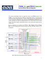
The block diagram below shows the signal flow when using Double Base configuration.
f_CameraLink_config
(first CL Module)
GiDEL’s IP
f_rx_base
f_rxclk_base
Camera
Transmitter
Control
Serial
2
Comm.
Transciever
4
Control
Serial
f_rxcc
(CL-in Control)
2
Comm.
f_rxSer
From/To
Camera
(CL-in Serial Comm.)
Data
Second
Base
Data
4
LVDS
Receiver
X[4..0]
CLKX
28
X[28..0]
s_rx_base
[28..0]
CLKX
s_rxclk_base
Connector
4
Camera
Control
Serial
Comm.
2
Camera
Transmitter
Transciever
Control
Serial
Comm.
PSDB_CL
4
s_rxcc
(CL-in Control)
2
s_rxSer
(CL-in Serial Comm.)
f_rxSerTC (1st camera serial comm.)
Camera
f_rxSerTFG (1st camera serial comm.)
4
f_FVAL, f_LVAL, f_DVAL, f_spare
(1st camera frame/line/data valid)
f_cc
(user 1st camera camera control)
optional host controls
s_tap / s_rgb*
(second image data channels)
s_strb_base
(second camera clock)
s_FVAL, s_LVAL, s_DVAL, s_spare
(2nd cameraframe/line/data valid)
s_cc
(user 2nd cameracamera control)
(optional)
CLKX
Connector
f_strb_base
(first camera clock)
2nd cam. host ctrl
[28..0]
(optional)
28
X[28..0]
1st cam. host ctrl
CLKX
(first image data channels)
s_rxSerTFG (2nd camera serial comm.)
LVDS
Receiver
X[4..0]
First
Base
Data
s_rxSerTC (2nd camera serial comm.)
4
_if Module
(PCI Interface for Camera Control)
optional host controls
s_user_CameraLink
(User’s Acquisition Module)
f_tap / f_rgb*
Data
f_user_CameraLink
(User’s Acquisition Module)
s_CameraLink_config
(second CL Module)
GiDEL’s IP
PROC Board
From/To PCI
*
Data channels may be tap8 / tap10 / tap12 / tap14 / tap16 / RGB24 / RGB30 / RGB36 in
Base / Medium / Full modes, or tap8 / tap10 / tap12 / tap14 / tap16 / RGB24 in Double
Base mode
** In Medium and Full modes, all the data transfers may be synchronized to the base channel. In
this case, a single strobe signal and a single validation signal will enter the user's design, instead
of separate signals for each channel as shown in the block diagram. To activate this option,
select Registered inputs in PROCWizard while configuring the CameraLink IP.
Figure 2: Signal flow for Double Base configuration
GiDEL PROCWizard automatically generates all the units shown in the above block diagrams, as well
as the top-level design. For more information, please refer to PROCWizard User Manual.
4