1
Serial Ports
5.1
5
OVERVIEW
Synchronous serial ports, or SPORTs, support a variety of serial data
communications protocols and can provide a direct interconnection
between processors in a multiprocessor system.
These ADSP-2100 family processors contain serial ports:
Processor
ADSP-2101
ADSP-2105
ADSP-2115
ADSP-2111
ADSP-2171
ADSP-2181
ADSP-21msp58/59
Number of
Serial Ports
2
1
2
2
2
2
2
The serial ports, designated SPORT0 and SPORT1, have some differences
that are described in this chapter. On the ADSP-2105, only SPORT1 is
provided.
5.2
DESCRIPTION
BASIC SPORT
Each SPORT has a five-pin interface:
Pin Name
SCLK
RFS
TFS
DR
DT
Function
Serial clock
Receive frame synchronization
Transmit frame synchronization
Serial data receive
Serial data transmit
Table 5.1 SPORT External Interface
5–1
5 Serial Ports
A SPORT receives serial data on its DR input and transmits serial data on
its DT output. It can receive and transmit simultaneously, for full duplex
operation. The data bits are synchronous to the serial clock SCLK, which is
an output if the processor generates this clock or an input if the clock is
generated externally. Frame synchronization signals RFS and TFS are used
to indicate the start of a serial data word or stream of serial words.
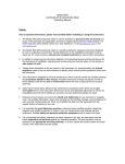
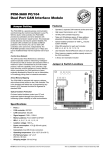
Figure 5.1, shows a simplified block diagram of a single SPORT. Data to
be transmitted is written from an internal processor register to the
SPORT’s TX register via the DMD bus. This data is optionally compressed
in hardware, then automatically transferred to the transmit shift register.
The bits in the shift register are shifted out on the SPORT’s DT pin, MSB
first, synchronous to the serial clock. The receive portion of the SPORT
accepts data from the DR pin, synchronous to the serial clock. When an
entire word is received, the data is optionally expanded, then
automatically transferred to the SPORT’s RX register, where it is available
to the processor.
The following is a list of SPORT characteristics. Many of the SPORT
characteristics are configurable to allow flexibility in serial
communication.
DMD Bus
16
16
16
Companding
Hardware
TXn
Transmit Data Register
RXn
Receive Data Register
16
16
Serial
Control
Transmit Shift Register
Receive Shift Register
Internal
Serial
Clock
Generator
DT
TFS
SCLK
Figure 5.1 Serial Port Block Diagram
5–2
RFS
DR
Serial Ports 5
• Bidirectional: each SPORT has independent transmit and receive
sections.
• Double-buffered: each SPORT section (both receive and transmit) has a
data register for transferring data words to and from other parts of the
processor and a register for shifting data in or out. The doublebuffering provides additional time to service the SPORT.
• Clocking: each SPORT can use an external serial clock or generate its
own in a wide range of frequencies down to 0 Hz. See Section 5.5.
• Word length: each SPORT supports serial data word lengths from
three to sixteen bits. See Section 5.6.
• Framing: each SPORT section (receive and transmit) can operate with
or without frame synchronization signals for each data word; with
internally-generated or externally-generated frame signals; with active
high or active low frame signals; with either of two pulse widths and
frame signal timing. See Section 5.7.
• Companding in hardware: each SPORT can perform A-law and µ-law
companding according to CCITT recommendation G.711. See
Section 5.10.
• Autobuffering with single-cycle overhead: using the DAGs, each
SPORT can automatically receive and/or transmit an entire circular
buffer of data with an overhead of only one cycle per data word.
Transfers between the SPORT and the circular buffer are automatic in
this mode and do not require additional programming. See
Section 5.11.
• Interrupts: each SPORT section (receive and transmit) generates an
interrupt upon completing a data word transfer, or after transferring
an entire buffer if autobuffering is used. See Section 5.13.
• Multichannel capability: SPORT0 can receive and transmit data
selectively from channels of a serial bitstream that is time-division
multiplexed into 24 or 32 channels. This is especially useful for T1
interfaces or as a network communication scheme for multiple
processors. See Section 5.12. Note: The ADSP-2105 has only one serial
port (SPORT1) and does not support multichannel operation.
• Alternate configuration: SPORT1 can be configured as two external
5–3
5 Serial Ports
interrupt inputs, IRQ0 and IRQ1, and the Flag In and Flag Out signals
instead of as a serial port. The internally generated serial clock may
still be used in this configuration. See Section 5.4.
5.2.1
Interrupts
Each SPORT has a receive interrupt and a transmit interrupt. The priority
of these interrupts is shown in Table 5.2.
Highest
Lowest
SPORT0 Transmit (on 2-SPORT processors)
SPORT0 Receive (on 2-SPORT processors)
SPORT1 Transmit
SPORT1 Receive
Table 5.2 SPORT Interrupt Priorities
For complete details about how interrupts are handled, see the
“Interrupts” section in Chapter 3, “Program Control.”
5.2.2
SPORT Operation
Writing to a SPORT’s TX register readies the SPORT for transmission; the
TFS signal initiates the transmission of serial data. Once transmission has
begun, each value written to the TX register is transferred to the internal
transmit shift register and subsequently the bits are sent, MSB first. Each
bit is shifted out on the rising edge of SCLK.
After the first bit (MSB) of a word has been transferred, the SPORT
generates the transmit interrupt. The TX register is now available for the
next data word, even though the transmission of the first word is ongoing.
In the receiving section, bits accumulate as they are received in an internal
receive register. When a complete word has been received, it is written to
the RX register and the receive interrupt for that SPORT is generated.
Interrupts are generated differently if autobuffering is enabled; see
“Autobuffering” later in this chapter.
5.3
PROGRAMMING
SPORT
To the programmer, the SPORT can be viewed as two functional sections.
5–4
Serial Ports 5
The configuration section is a block of control registers (mapped to data
memory) that the program must initialize before using the SPORTs. The
data section is a register file used to transmit and receive values through
the SPORT.
5.3.1
SPORT Configuration
SPORT configuration is accomplished by setting bit and field values in
configuration registers. These registers are memory mapped in data
memory space. SPORT0 configuration registers occupy locations 0x3FF3
to 0x3FFA; SPORT1 configuration registers occupy locations 0x3FEF to
0x3FF2. The contents of these registers are summarized in Table 5.3 and in
the register summary in Appendix E. The effects of the various settings
are described at length in the sections that follow.
Address
0x3FFA
0x3FF9
0x3FF8
0x3FF7
0x3FF6
0x3FF5
0x3FF4
0x3FF3
0x3FF2
0x3FF1
0x3FF0
0x3FEF
Contents
SPORT0* multichannel receive word enables (31-16)
SPORT0* multichannel receive word enables (15-0)
SPORT0* multichannel transmit word enables (31-16)
SPORT0* multichannel transmit word enables (15-0)
SPORT0* control register
Multichannel mode controls
Serial clock source
Frame synchronization controls
Companding mode
Serial word length
SPORT0* serial clock divide modulus (determines frequency)
SPORT0* receive frame sync divide modulus (determines frequency)
SPORT0* autobuffer control register
SPORT1 control register
Flag output value
Serial clock source
Frame synchronization controls
Companding mode
Serial word length
SPORT1 serial clock divide modulus (determines frequency)
SPORT1 receive frame sync divide modulus (determines frequency)
SPORT1 autobuffer control register (not on ADSP-21msp58/59)
*SPORT0 configuration registers are defined only on processors that have both SPORT0 and SPORT1
Table 5.3 SPORT Configuration Registers
There are two ways to initialize or to change values in SPORT
5–5
5 Serial Ports
configuration registers: write a register to an immediate address
(instruction type 3) or write immediate data to an indirect address
(instruction type 2). With either method, it is important to configure the
serial port before enabling it.
The first method of programming configuration registers requires no
setup of DAG registers but does require two instructions to perform the
write. For example:
AX0 = 0x6B27;
DM(0x3FF2) = AX0;
AX0 = 0;
DM(0x3FF3) = AX0;
{the contents of AX0 are written}
{to the address 0x3FF2}
{the contents of AX0 are written}
{to address 0x3FF3}
In the second method, the DAG (I) index register must contain the data
memory address of the configuration register to be written. The modify
(M) register, which updates the I register after the write, must also contain
a valid value. And the length (L) register that has the same number as the
I register must be initialized to zero so that the circular buffer capability is
not active. For example:
I0 = 0x3FF2;
M0 = 1;
L0 = 0;
DM(I0,M0) = 0x6B27;
{the constant 0x6B27 is written to
}
{address pointed to by I0; pointer
}
DM(I0,M0) = 0;
{then modified by M0}
{address 0x3FF3 is set to 0}
Either method works. The second method requires only one cycle to
configure the registers once the I, M and L registers are initialized. This
method is, however, more prone to error because the registers are written
indirectly. You must make sure that the I register contains the intended
value before the write.
5.3.2
Receiving And Transmitting Data
Each SPORT has a receive register and a transmit register. These registers
are not memory mapped, but are identified by assembler mnemonics. The
transmit registers are named TX0 and TX1, for SPORT0 and SPORT1
respectively. Receive registers are named RX0 and RX1 for SPORT0 and
SPORT1 respectively. These registers can be accessed at any time during
program execution using a data memory access with immediate address,
5–6
Serial Ports 5
load of a non-data register with immediate data or register-to-register
move (instruction types 3, 7 and 17). For example, the following
instruction would ready SPORT1 to transmit a serial value, assuming
SPORT1 is configured and enabled:
TX1 = AX0;
{the contents of AX0 are transmitted}
{on SPORT1}
The following instruction would access a serial value received on SPORT0:
AY0 = RX0;
{the contents of SPORT0 receive register}
{is transferred to AY0}
Because the SPORTs are interrupt driven, these instructions would
typically be executed within a interrupt service routine in response to a
SPORT interrupt.
5.4
SPORT ENABLE
SPORTs are enabled through bits in the system control register. This
register is mapped to data memory address 0x3FFF. Bit 12 enables
SPORT0 if it is a 1, and bit 11 enables SPORT1 if it is a 1. Both of these bits
System Control Register
0x3FFF
15
14
13
12
11
10
9
8
7
6
5
4
3
2
1
0
SPORT1 Configure
1 = serial port, 0 = FI, FO, IRQ0, IRQ1, SCLK
SPORT1 Enable
1 = enabled, 0 = disabled
SPORT0 Enable
1 = enabled, 0 = disabled
Figure 5.2 SPORT Enables In The System Control Register
5–7
5 Serial Ports
are cleared at reset, disabling both SPORTs.
Bit 10 of the system control register determines the configuration of
SPORT1, either as a serial port or as interrupts and flags, according to
Table 5.4 on the next page. If bit 10 is a 1, SPORT1 operates as a serial port;
if it is a 0, the alternate functions are in effect (and bit 11 is ignored). At
reset, bit 10 is a 1, so SPORT1 functions as a serial port.
Pin Name
RFS1
TFS1
DR1
DT1
SCLK1
Alternate Name
IRQ0
IRQ1
FI
FO
Same
Alternate Function
External interrupt 0
External interrupt 1
Flag input
Flag output
Same
Table 5.4 SPORT1 Alternate Configuration
5.5
SERIAL CLOCKS
Each SPORT operates on its own serial clock signal. The serial clock
(SCLK) can be internally generated or received from an external source.
The ISCLK bit, bit 14 in either the SPORT0 or SPORT1 control register,
determines the SCLK source for the SPORT. If this bit is a 1, the processor
generates the SCLK signal; if it is a 0, the processor expects to receive an
external clock signal on SCLK. At reset, ISCLK is cleared, so both serial
ports are in the external clock mode. When ISCLK is set, internal
generation of the SCLK signal begins on the next instruction cycle,
whether or not the corresponding SPORT is enabled.
SPORT0 Control Register: 0x3FF6
SPORT1 Control Register: 0x3FF2
15
14
ISCLK
13
12
11
10
9
8
7
6
0 = External (Default)
1 = Internal
Figure 5.3 ISCLK Bit In SPORT Control Register
5–8
5
4
3
2
1
0
Serial Ports 5
External serial clock frequencies may be as high as the processor’s cycle
rate, up to a maximum of 13.824 MHz; internal clock frequencies may be
as high as one-half the processor’s clock rate. The frequency of an
internally generated clock is a function of the processor clock frequency
(as seen at the CLKOUT pin) and the value of the 16-bit serial clock divide
modulus register SCLKDIV (0x3FF5 for SPORT0 and 0x3FF1 for SPORT1).
CLKOUT frequency
SCLK frequency = –––––––––––––––––—
2 x (SCLKDIV + 1)
Table 5.5 shows how some common SCLK frequencies correspond to
values of SCLKDIV.
SCLKDIV
20479
5119
639
95
3
2
0
SCLK Frequency
300 Hz
1200 Hz
9600 Hz
64 kHz
1.536 MHz
2.048 MHz
6.144 MHz
(Assumes CLKOUT frequency of 12.288 MHz)
Table 5.5 Common Serial Clock Frequencies (Internally Generated)
If the value of SCLKDIV is changed while the internal serial clock is
enabled, the change in SCLK frequency takes effect at the start of the next
rising edge of SCLK.
Note that the serial clock of SPORT1 (the SCLK pin) still functions when
the port is being used in its alternate configuration (as FO, FI and two
interrupts). In this case, SCLK is unresponsive to an external clock, but can
internally generate a clock signal as described above.
5.6
WORD LENGTH
Each SPORT independently handles words of 3 to 16 bits. The data is
right-justified in the SPORT data registers if it is fewer than 16 bits long.
The serial word length (SLEN) field in each SPORT control register
determines the word length according to this formula:
Serial Word Length = SLEN + 1
5–9
5 Serial Ports
SPORT0 Control Register: 0x3FF6
SPORT1 Control Register: 0x3FF2
15
14
13
12
11
10
9
8
7
6
5
4
3
2
1
0
SLEN (Serial Word Length – 1)
Figure 5.4 SLEN Field In SPORT Control Register
For example, if you are using 8-bit serial words, set SLEN to 7 (0111
binary). The SLEN field is bits 3-0 in the SPORT control register (0x3FF6
for SPORT0 and 0x3FF2 for SPORT1). See Figure 5.4 on the next page.
Do not set SLEN to zero or one; these SLEN values are not permitted.
5.7
OPTIONS
WORD FRAMING
Framing signals identify the beginning of each serial word transfer. The
SPORTs have many ways of handling framing signals. Transmit and
receive framing are independent of each other. All frame sync signals are
sampled on the falling edge of the serial clock (SCLK).
SPORT0 Control Register: 0x3FF6
SPORT1 Control Register: 0x3FF2
15
14
13
12
11
10
9
8
7
6
5
4
3
2
1
0
0= Transmit
Frame
Sync
Required 1st Word
TFSR (Transmit
Frame
Sync
Required)
1= Transmit Frame Sync Required Every Word
RFSR
0= Receive
Frame
Sync
Required 1st Word
RFSR (Receive
Frame
Sync
Required)
1= Receive Frame Sync Required Every Word
Figure 5.5 TFSR And RFSR Bits In SPORT Control Register
5 – 10
Serial Ports 5
5.7.1
Frame Synchronization
Word framing signals are optional. If the receive frame sync required
(RFSR) or transmit frame sync required (TFSR) bit in the SPORT control
register is a 0, a frame sync signal is necessary to initiate communications
but is ignored after the first bit is transferred. Words are then transferred
continuously, unframed. If the RFSR or TFSR bit is a 1, a frame sync signal
is required at the start of every data word.
The RFSR bit is bit 13 in the SPORT control register (0x3FF6 for SPORT0
and 0x3FF2 for SPORT1), and the TFSR bit is bit 11. These bits are both
cleared at reset, so that communication in both directions on both serial
ports is unframed.
See “Configuration Examples” later in this chapter for examples of frame
sync timing.
5.7.2
Frame Sync Signal Source
The processor can generate frame synchronization signals internally or
receive them from an external source. The sources for transmit frame
syncs and receive frames syncs can be set independently. If the internal
receive frame sync (IRFS) bit or internal transmit frame sync (ITFS) bit in
the SPORT control register is a 0, the processor expects to receive a signal
SPORT0 Control Register: 0x3FF6
SPORT1 Control Register: 0x3FF2
15
14
13
12
11
10
9
8
7
6
5
4
3
2
1
0
IRFS 0= External RFS (Input)
IRFS
(Internal1=Receive
Sync Required)
InternalFrame
RFS (Output)
ITFS
ITFS
0= External TFS (Input)
(Internal1=
Transmit
Sync Required)
Internal Frame
TFS (Output)
Figure 5.6 ITFS And IRFS Bits In SPORT Control Register
5 – 11
5 Serial Ports
on its frame sync pin (RFS or TFS). If the IRFS or ITFS bit is a 1, the
processor generates its own frame sync signal and drives the RFS or TFS
pin as an output.
The IRFS bit is bit 8 in the SPORT control register (0x3FF6 for SPORT0 and
0x3FF2 for SPORT1), and the ITFS bit is bit 9. Both of these bits are cleared
at reset, that is, both serial ports require externally generated frame sync
signals for both transmitting and receiving data.
If frame sync signals are generated externally, then RFS and TFS are
inputs, and the external source controls data transmission and reception.
The SPORT will wait for a transmit frame sync before transmitting data
and for a receive frame sync before receiving data. If frame sync signals
are generated internally, however, then RFS and TFS are outputs, and the
processor controls the timing of data operations.
The SPORT outputs an internally generated transmit framing signal after
data is loaded into the transmit (TX0 or TX1) register, at the time needed
to ensure continuous data transmission, after the last bit of the current
word is transmitted (the exact time depends on the framing mode being
used; see “Normal and Alternate Framing Modes,” the next section). The
occurrence of the transmit frame sync is a result of the availability of data
in the transmit register.
With an internally generated receive framing signal, the processor controls
the timing of the receive data. The external data source must provide data
to the serial port synchronized to the receive framing signal (the timing
depends on the framing mode being used; see “Normal and Alternate
Framing Modes,” the next section). The processor generates RFS
periodically on a multiple of SCLK cycles, based on the value of the 16-bit
receive frame sync divide modulus register, RFSDIV (0x3FF4 for SPORT0
and 0x3FF0 for SPORT1):
Number of SCLK cycles between RFS assertions = RFSDIV + 1
For example, to allow 256 SCLK cycles between RFS assertions, set
RFSDIV to 255 (0xFF).
Values of RFSDIV+1 that are less than the word length are not
recommended.
Note that frame sync signals may be generated internally even when
5 – 12
Serial Ports 5
SCLK is supplied externally. This provides a way to divide external clocks
for any purpose.
You can also use one frame sync to generate a single signal for both
transmit and receive data. For example, an internally generated RFS
(output) could be connected to an externally generated TFS (input) on the
same SPORT for simultaneous transmit and receive operations. This
interconnection is especially useful for combo codec interfaces.
5.7.3
Normal And Alternate Framing Modes
In the normal framing mode, the framing signal is checked at the falling
edge of SCLK. If the framing signal is asserted, received data is latched on
the next falling edge of SCLK and transmitted data is driven on the next
rising edge of SCLK. The framing signal is not checked again until the
word has been transmitted or received. If data transmission or reception is
continuous, i.e., the last bit of one word is followed without a break by the
first bit of the next word, then the framing signal should occur in the same
SCLK cycle as the last bit of each word.
In the alternate framing mode, the framing signal should be asserted in
the same SCLK cycle as the first bit of a word. Received data bits are
latched on the falling edge of SCLK and transmitted bits are driven on the
rising edge of SCLK, but the framing signal is checked only on the first bit.
Internally generated frame sync signals remain asserted for the length of
the serial word. Externally generated frame sync signals are only checked
during the first bit time.
SPORT0 Control Register: 0x3FF6
SPORT1 Control Register: 0x3FF2
15
14
13
12
11
10
9
8
7
6
5
4
3
2
1
0
TFSW
Framing
TFSW0=Normal
(TransmitTransmit
Frame Sync
Width)
1=Alternate Transmit Framing
RFSW0=Normal
(ReceiveReceive
Frame Sync
Width)
RFSW
Framing
1=Alternate Receive Framing
Figure 5.7 TFSW And RFSW Bits In SPORT Control Register
5 – 13
5 Serial Ports
Framing modes for receiving and transmitting data are independent. If the
receive frame sync width (RFSW) bit or transmit frame sync width (TFSW)
bit in the SPORT control register is a 0, normal framing is enabled. If the
RFSW or TFSW bit is a 1, alternate framing is used. The RFSW bit is bit 12
in the SPORT control register (0x3FF6 for SPORT0 and 0x3FF2 for
SPORT1), and the TFSW bit is bit 10. These bits are both cleared at reset,
so that normal framing in both directions is enabled.
For examples of normal and alternate framing, see “Configuration
Examples” later in this chapter.
5.7.4
Active High Or Active Low
Framing sync signals for receiving and transmitting data can be either
active high or active low and are configured independently. If the invert
RFS (INVRFS) bit or invert TFS (INVTFS) bit in the SPORT control register
is a 0, the corresponding frame sync signal is active high. If the INVRFS or
INVTFS bit is a 1, the frame sync signal is active low. These controls apply
SPORT0 Control Register: 0x3FF6
SPORT1 Control Register: 0x3FF2
15
14
13
12
11
10
9
8
7
6
5
4
3
2
1
0
INVRFS
High RFS
INVRFS0=Active
(Invert Receive
Framing1=Active
Signal)Low RFS
INVTFS (Invert
0=Active
High TFS
INVTFS
Transmit
1=Active Low TFS
Framing Signal)
Figure 5.8 INVTFS And INVRFS Bits In SPORT Control Register
5 – 14
Serial Ports 5
regardless of the source of frame sync signals; they either control the
polarity of internally generated signals or determine how externally
generated signals are interpreted.
The INVRFS bit is bit 6 in the SPORT control register (0x3FF6 for SPORT0
and 0x3FF2 for SPORT1), and the INVTFS bit is bit 7. These bits are both
cleared at reset, so that frame sync signals are active high.
5.8
CONFIGURATION EXAMPLE
The example code that follows illustrates how to configure the SPORTs.
This example configures both SPORT0 and SPORT1. SPORT0 is
configured for an internally generated serial clock (SCLK), internally
generated frame synchronization, and µ-law companded 8-bit data. This is
a typical setup for communication with a combo codec. SPORT1 is
configured for an externally generated serial clock, externally generated
frame synchronization, non-companded 16-bit data and autobuffering.
This setup could be used to transfer data between processors in a
multiprocessor system.
Only the needed memory mapped registers are initialized. Notice that the
SPORTs are configured before they are enabled and that any extraneous
latched interrupts are cleared before interrupts are enabled.
{——
SPORT INITIALIZATION CODE
——}
{SPORT1 inits }
AX0 = 0x0017;
DM(0x3FEF) = AX0;
AX0 = 0x280F;
DM(0x3FF2) = AX0;
{enable SPORT1 autobuffering}
{TX autobuffer uses I0 and M0}
{RX autobuffer uses I1 and M1}
{external serial clock, RFS and
TFS}
{RFS and TFS are required, normal}
{framing, no companding and 16
bits}
(continued on next page)
5 – 15
5 Serial Ports
(continued from previous page)
{SPORT0 inits}
{Assumes a CLKIN of 12.288 MHz. Internally generated}
{SCLK will be 2.048 MHz, and framing sync of 8 kHz}
AX0 = 255;
DM(0x3FF4) = AX0;
AX0 = 2;
DM(0x3FF5) = AX0;
AX0 = 0x6B27;
DM(0x3FF6) = AX0;
{RFSDIV = 256, 256 SCLKs between}
{frame syncs: 8 kHz framing}
{SCLK = 2.048 MHz}
{internal SCLK, RFS and TFS}
{normal framing, mu-law companding}
{8 bit words}
{SPORT ENABLE}
IFC = 0x1E;
interrupts}
ICNTL = 0;
{clear any extraneous SPORT
{interrupt nesting disabled}
AX0 = 0x1C1F;
DM(0x3FFF) = AX0;
{both SPORTs enabled, BWAIT and}
{PWAIT left as default}
IMASK = 0x1E;
{SPORT interrupts are enabled}
{——
END SPORT INITIALIZATIONS
——}
Figure 5.9 Example SPORT Configuration Code
5.9
EXAMPLES
TIMING
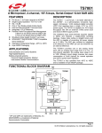
This section contains examples of some combinations of the various
framing options. The timing diagrams show relationships between
signals, but are not scaled to show the actual timing parameters of the
processor. Consult the data sheet for actual timing parameters and values.
The examples assume a word length of four bits, that is, SLEN = 3.
Framing signals are active high, that is, INVRFS = 0 and INVTFS = 0.
5 – 16
The value of the SPORT control register (0x3FF6 for SPORT0 and 0x3FF2
for SPORT1) is shown for each example. In these binary values, 1= high, 0
Serial Ports 5
SCLK
RFS
RFS
OUTPUT
INPUT
DR
B3
B2
B1
B0
B3
B2
B1
B0
B1
B0
B3
B2
SPORT Control Register:
Internal Frame Sync
0X10 XXX1 X0XX 0011
External Frame Sync
0X10 XXX0 X0XX 0011
Both Internal Framing Option and External Framing Option Shown
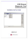
Figure 5.10 SPORT Receive, Normal Framing
SCLK
RFS
OUTPUT
RFS
INPUT
DR
B3
B2
B1
B0
B3
B2
SPORT Control Register:
Internal Frame Sync
0X10 XXX1 X0XX 0011
External Frame Sync
0X10 XXX0 X0XX 0011
Both Internal Framing Option and External Framing Option Shown
Figure 5.11 SPORT Continuous Receive, Normal Framing
5 – 17
5 Serial Ports
SCLK
RFS
RFS
OUTPUT
INPUT
DR
B3
B2
B1
B0
B3
B2
B1
SPORT Control Register:
Internal Frame Sync
0X11 XXX1 X0XX 0011
External Frame Sync
0X11 XXX0 X0XX 0011
Both Internal Framing Option and External Framing Option Shown
Figure 5.12 SPORT Receive, Alternate Framing
SCLK
RFS
RFS
OUTPUT
INPUT
DR
B3
B2
B1
B0
B3
B2
SPORT Control Register:
Internal Frame Sync
0X11 XXX1 X0XX 0011
External Frame Sync
0X11 XXX0 X0XX 0011
Both Internal Framing Option and External Framing Option Shown
Figure 5.13 SPORT Continuous Receive, Alternate Framing
5 – 18
B1
B0
B0
Serial Ports 5
= low, and X can be either. The underlined bit values are the bits which
set the modes illustrated in the example.
Figures 5.10 to 5.15 show framing for receiving data. In Figures 5.10 and
5.11, the normal framing mode is shown for noncontinuous data (any
number of SCLK cycles between words) and continuous data (no SCLK
cycles between words). Figures 5.12 and 5.13 show noncontinuous and
SCLK
RFS
DR
B3
B2
B1
B0
B3
B2
B1
B0
B3
B2
B1
B0
B3
B2
SPORT Control Register:
Internal Frame Sync
0X00 XXX1 X0XX 0011
External Frame Sync
0X00 XXX0 X0XX 0011
Figure 5.14 SPORT Receive, Unframed Mode, Normal Framing
SCLK
RFS
DR
B3
B2
B1
B0
B3
B2
SPORT Control Register:
Internal Frame Sync
0X01 XXX1 X0XX 0011
External Frame Sync
0X01 XXX0 X0XX 0011
Figure 5.15 SPORT Receive, Unframed Mode, Alternate Framing
5 – 19
5 Serial Ports
continuous receiving in the alternate framing mode. In these four figures,
both the input timing requirement for an externally generated frame sync
and the output timing characteristic of an internally generated frame sync
are shown. Note that the output meets the input timing requirement; thus,
on processors with two SPORTs, one SPORT could provide RFS for the
other.
SCLK
TFS
OUTPUT
TFS
INPUT
B3
DT
B2
B1
B0
B3
B2
B1
B0
B3
B0
SPORT Control Register:
Internal Frame Sync
0XXX 101X 0XXX 0011
External Frame Sync
0XXX 100X 0XXX 0011
Both Internal Framing Option and External Framing Option Shown
Figure 5.16 SPORT Transmit, Normal Framing
SCLK
TFS
TFS
OUTPUT
INPUT
DT
B3
B2
B1
B0
B3
B2
B1
SPORT Control Register:
Internal Frame Sync
0XXX 101X 0XXX 0011
External Frame Sync
0XXX 100X 0XXX 0011
Both Internal Framing Option and External Framing Option Shown
Figure 5.17 SPORT Continuous Transmit, Normal Framing
5 – 20
B2
Serial Ports 5
SCLK
TFS OUTPUT
TFS INPUT
DT
B3
B2
B1
B0
B3
B2
B1
B0
SPORT Control Register:
Internal Frame Sync
0XXX 111X 0XXX 0011
External Frame Sync
0XXX 110X 0XXX 0011
Both Internal Framing Option and External Framing Option Shown
Note: There is an asynchronous delay between TFS input and DT. See the appropriate
data sheet for specifications.
Figure 5.18 SPORT Transmit, Alternate Framing
SCLK
TFS
TFS
DT
OUTPUT
INPUT
B3
B2
B1
B0
B3
B2
B1
B0
SPORT Control Register:
Internal Frame Sync
0XXX 111X 0XXX 0011
External Frame Sync
0XXX 110X 0XXX 0011
Both Internal Framing Option and External Framing Option Shown
Note: There is an asynchronous delay between TFS input and DT. See the appropriate
data sheet for specifications.
Figure 5.19 SPORT Continuous Transmit, Alternate Framing
5 – 21
5 Serial Ports
Figures 5.14 and 5.15 show the receive operation with normal framing and
alternate framing, respectively, in the unframed mode. There is a single
the frame sync signal that occurs only at the start of the first word, either
one SCLK before the first bit (normal) or at the same time as the first bit
(alternate). This mode is appropriate for multiword bursts (continuous
reception).
SCLK
TFS
DT
B3
B2
B1
B0
B3
B2
B1
B0
B3
B2
B3
B2
SPORT Control Register:
Internal Frame Sync
0XXX 001X 0XXX 0011
External Frame Sync
0XXX 000X 0XXX 0011
Figure 5.20 SPORT Transmit, Unframed Mode, Normal Framing
SCLK
TFS
DT
B3
B2
B1
B0
B3
B2
B1
B0
SPORT Control Register:
Internal Frame Sync
0XXX 011X 0XXX 0011
External Frame Sync
0XXX 010X 0XXX 0011
Note: There is an asynchronous delay between TFS input and DT. See the appropriate
data sheet for specifications.
Figure 5.21 SPORT Transmit, Unframed Mode, Alternate Framing
5 – 22
Serial Ports 5
Figures 5.16 to 5.21 show framing for transmitting data and are very
similar to Figures 5.10 to 5.15. In Figures 5.16 and 5.17, the normal framing
mode is shown for noncontinuous data and continuous data. Figures 5.18
and 5.19 show noncontinuous and continuous transmission in the
alternate framing mode. As with receive timing, the TFS output meets the
TFS input timing requirement.
Figures 5.20 and 5.21 show the transmit operation with normal framing
and alternate framing, respectively, in the unframed mode. There is a
single the frame sync signal that occurs only at the start of the first word,
either one SCLK before the first bit (normal) or at the same time as the first
bit (alternate).
5.10
COMPANDING AND DATA FORMAT
Companding (a contraction of COMpressing and exPANDing) is the
process of logarithmically encoding and decoding data to minimize the
number of bits that must be sent. Both SPORTs share the companding
hardware; one expansion and one compression operation can occur in
each processor cycle. In the event of contention, SPORT0 has priority.
SPORT0 Control Register: 0x3FF6
SPORT1 Control Register: 0x3FF2
15
14
13
12
11
10
DTYPE
9
8
7
6
5
4
3
2
1
0
00=Right justify, zero fill unused MSBs
01=Right justify, sign extend into unused MSBs
10=Compand using µ-law
11=Compand using A-law
Figure 5.22 DTYPE Field In SPORT Control Register
5 – 23
5 Serial Ports
The ADSP-2100 family of processors supports both of the widely used
algorithms for companding: A-law and µ-law. The processor compands
data according to the CCITT G.711 recommendation. The type of
companding can be selected independently for each SPORT.
If companding is not enabled, there are two formats available for received
data words of fewer than 16 bits: one that fills unused MSBs with zeros,
and another that sign-extends the MSB into the unused bits.
The type of companding, as well as the non-companding data format, are
controlled by the DTYPE field (bits 5-4) in the SPORT control register
(0x3FF6 for SPORT0 and 0x3FF2 for SPORT1) as shown in Figure 5.22.
When companding is enabled, valid data in the RX0 or RX1 register is the
right-justified, sign-extended, expanded value of the eight LSBs received.
Likewise, a write to TX0 or TX1 causes the 16-bit value to be compressed
to eight LSBs (sign-extended to the width of the transmit word) before
being written to the internal transmit register. If the magnitude of the 16bit value is greater than the 13-bit A-law or 14-bit µ-law maximum, the
value is automatically compressed to the maximum positive or negative
value.
5.10.1 Companding Operation Example
With hardware companding, interfacing to a codec requires little
additional programming effort. See the codec hardware interfacing
example in the last section of this chapter.
Here is a typical sequence of operations for transmitting companded data:
•
•
•
•
Write data to the TXn register
The value in TXn is compressed
The compressed value is written back to TXn
After the frame sync signal has occurred (if required), TXn is written to
the internal transmit register and the bits are sent, MSB first.
As soon as the SPORT has started to send the second bit of the current
word, TXn can be written with the next word, even though transmission
of the first is not complete. After the MSB has been transferred, the SPORT
5 – 24
Serial Ports 5
generates the transmit interrupt to indicate that TXn is ready for the next
data word. If the framing signal is being provided externally, the next
word must be written to TXn early enough to allow for compression
before the next framing signal arrives.
Here is a typical sequence of operations for receiving companded data:
•
•
•
•
Bits accumulate as received in the internal receive register
When a complete word is received, it is written to RXn
The value in RXn is expanded
The expanded value is written back to RXn
The receive interrupt for that SPORT is then generated.
5.10.2 Contention For Companding Hardware
Since both SPORTs share the companding hardware, only one
compression and one expansion operation can take place during a single
machine cycle. If contention arises, such as when two expansions need to
occur in the same cycle, SPORT0 has priority, while SPORT1 is forced to
wait one cycle.
The effects of contention, however, are usually small. The instruction set
does not support loading both TX0 and TX1 in the same cycle;
consequently these operations will be naturally out of phase for
contention in many cases. The overhead cycle for the receive operation
occurs prior to the receive interrupt and does not increase the time needed
to service the interrupt, although it does affect the latency prior to
receiving the interrupt.
5.10.3 Companding Internal Data
Because the values in the RX and TX registers are actually companded “in
place” it is possible to use the companding hardware internally, without
any transmission or reception at all and without enabling the serial port.
This operation can be used for debugging or data conversion and requires
a single cycle of overhead.
To compress data, enable companding and then:
1. Write data to TXn (compression is calculated).
2. Wait for one cycle (TXn is written with compressed value)
3. Read TXn (it returns the 8-bit compressed data)
5 – 25
5 Serial Ports
The code might look like this:
TX0 = AX0;
NOP;
AX1 = TX0;
{linear data written to transmit register}
{any instruction}
{compressed data transferred to AX1}
Use the same procedure to expand data, but use RXn instead of TXn.
RX0 = AX0;
NOP;
AX1 = RX0;
5.11
{compressed data written to receive register}
{any instruction}
{expanded - linear value transferred to AX1}
AutoBuffering
In normal operation, a SPORT generates an interrupt when it has received
or has started to transmit a data word. Autobuffering provides a
mechanism for receiving or transmitting an entire block of serial data
before an interrupt is generated. Service routines can operate on the entire
block of data, rather than on a single word, reducing overhead
significantly. Autobuffering is available on both SPORT0 and SPORT1,
except on the ADSP-21msp58/59 which autobuffers only on SPORT0.
Autobuffering uses the circular buffer addressing capability of the DAGs.
With autobuffering enabled, each serial data word is transferred (or if
multichannel operation is enabled, each active word is transferred) to or
from data memory in a single overhead cycle. (Autobuffering to program
memory is not supported.) This overhead cycle occurs independently of
the instructions being executed and effectively suspends execution for one
cycle (or more, if wait states are required) when it happens. No interrupt
is generated for these individual data word transfers.
The autobuffer transfer cannot be duplicated by any instruction. However,
an equivalent assembly language instruction would be:
DM(I,M) = RX0
or
Equivalent Instructions Only
TX0 = DM(I,M)
The I and M registers used in the transfer are selected by fields in the
SPORT’s autobuffer control register.
The processor waits for the current instruction to finish before inserting
5 – 26
Serial Ports 5
the overhead cycle. A delay in the autobuffer transfer occurs if the transfer
is required during an instruction executing in multiple cycles (for wait
states, for example). If the transfer is required when the processor is
waiting in an IDLE state, the transfer is executed and the processor returns
to IDLE.
When a data word transfer causes the circular buffer pointer to wrap
around, the SPORT interrupt is generated. The receive interrupt occurs
after the complete buffer has been received. The transmit interrupt occurs
when the last word is loaded into TXn, prior to transmission.
Aside from the completion of an instruction requiring multiple cycles, the
automatic transfer of individual data words has the highest priority of any
operation short of RESET, including all interrupts. Thus, it is possible for
an autobuffer transfer to increase the latency of an interrupt response if
the interrupt happens to coincide with the transfer. Up to four
autobuffered transfers can occur; in the case that two or more are needed
in the same cycle, they have the following priority, which is the same as
the SPORT interrupt priority:
Highest
SPORT0 Transmit
SPORT0 Receive
SPORT1 Transmit
SPORT1 Receive
Lowest
SPORT0 Autobuffer Control Register: 0x3FF3
SPORT1 Autobuffer Control Register: 0x3FEF
15
14
13
12
11
10
TIREG
9
8
7
TMREG
6
5
RIREG
4
3
2
1
0
RMREG
TBUF
(Transmit Autobuffering Enable)
RBUF
(Receive Autobuffering Enable)
Figure 5.23 SPORT Autobuffer Control Register
5 – 27
5 Serial Ports
In the worst case that all four autobuffer transfers are required at about
the same time, interrupt latency would increase by the time it takes for all
the transfers to occur, which is affected by wait states and bus request.
5.11.1 Autobuffering Control Register
In autobuffering mode, an interrupt is generated when the modification of
a specified I register (in the DAG) by the value in the specified M register
(in the DAG) causes a modulus overflow (pointer wraparound). This
means that the end of the buffer has been detected.
The autobuffering mode is enabled separately for receiving and
transmitting by bits in the SPORT’s autobuffer control register (0x3FF3 for
SPORT0 or 0x3FEF for SPORT1), shown in Figure 5.23.
The I and M registers used for autobuffering are identified by fields in the
autobuffer control register. TIREG and TMREG are binary values that
indicate the numbers of the I and M registers, respectively, associated with
the transmit buffer. The rules governing the pairing of I and M registers
are the same as for other DAG operations: the I and M registers must be in
the same DAG, numbered either 0-3 for DAG1 or 4-7 for DAG2.
Consequently, three bits identify the I register, but only two bits are
necessary to indicate the M register because the third bit (MSB) of the M
register number must be the same as for the I register.
Likewise, RIREG and RMREG indicate the numbers of the I and M
registers, respectively, associated with the receive buffer.
The TBUF and RBUF bits enable transmit autobuffering and receive
autobuffering, respectively. These bits are cleared to zeros at reset and
after a reboot. Consequently, autobuffering in progress cannot continue
through a reboot operation; you must re-enable autobuffering after a
reboot.
5.11.2 Autobuffering Example
The code shown below is an example that sets up SPORT1 for
autobuffering operation. The code assumes that the processor is driven
with a clock frequency of 12.288 MHz. The SPORT will automatically
transmit values from the circular buffer named tx_buffer. It will receive
values as they are sent to the SPORT and automatically transfer the data
into the buffer named rx_buffer. A transmit interrupt will be generated
once all of the tx_buffer values have been transferred to TX1, but before the
5 – 28
Serial Ports 5
last value has been loaded into the transmit shift register. A receive
interrupt will be generated once the rx_buffer has been completely filled.
.MODULE/RAM
{——
code_to_init_AB_SPORT1;
Initialization code for autobuffer
.VAR/DM/CIRC
.VAR/DM/CIRC
.ENTRY
——}
tx_buffer[10];
rx_buffer[10];
sport1_inits;
{set up I,M, and L registers}
sport1_inits:
tx_buffer}
I0 = ^tx_buffer; {I0 contains address of
M0 = 1;
{fill every location}
L0 = %tx_buffer; {L0 set to length of tx_buffer}
I1 = ^rx_buffer; {I1 points to rx_buffer}
L1 = %rx_buffer; {L1 set to length of rx_buffer}
{set up SPORT1 for autobuffering}
AX0 = 0x0013;
{TX uses I0, M0; RX uses I1, M0}
DM(0x3FEF) = AX0; {autobuffering enabled}
{set up SPORT1 for 8 kHz sampling and 2.048 MHz SCLK}
AX0 = 255;
{set RFSDIV to 255 for 8 kHz}
DM(0x3FF0) = AX0;
AX0 = 2;
{set SCLKDIV to 2 for 2.048 MHz SCLK}
DM(0x3FF5) = AX0;
{set up SPORT1 for normal required framing, internal SCLK}
{internal generated framing}
AX0 = 0x6B27;
{normal framing, 8 bit mu-law}
DM(0x3FF2) = AX0; {internal clock, framing}
{set up interrupts}
IFC = 6;
{clear any extraneous SPORT
ICNTL = 0;
{interrupt nesting disabled}
interrupts}
5 – 29
5 Serial Ports
IMASK = 6;
{enable SPORT1 interrupts}
{enable SPORT1}
AX0 = 0x0C1F;
DM(0x3FFF) = AX0;
{enable SPORT1 leave PWAIT,}
{BWAIT as default}
{Place first transfer value into TX1}
AX0 = DM(I0,M0);
TX1 = AX0;
RTS;
.ENDMOD;
Figure 5.24 Autobuffering Example Configuration Code
5.12
MULTICHANNEL FUNCTION
SPORT0 supports a multichannel function. In the multichannel mode of
operation, serial data is time-division multiplexed. Each subsequent word
belongs to the next consecutive channel so that, for example, a 24-word
block of data contains one word for each of 24 channels. SPORT0 supports
32 or 24 channels and can automatically select words for particular
channels while ignoring the others.
SPORT0 Control Register (Multichannel Version)
0x3FF6
15
14
13
12
11
10
9
8
7
6
5
4
3
2
1
0
1
MFD
(Multichannel
Frame Delay)
MCE
(Multichannel Enable)
1 = Multichannel Operation
INVTDV (Invert Transmit Data Valid)
MCL (Multichannel Length)
0 = 24 Words
1 = 32 Words
In single-channel mode, receive and transmit framing identifies the start of
5 – 30
Serial Ports 5
a single word or continuous stream, with independent receive and
transmit operation. In the multichannel mode, the receive frame sync
signal (RFS0) identifies the start of a 24- or 32-word block of serial data
with the receiver and transmitter operating in parallel. TFS0 has an
alternate function, described below. Note: The ADSP-2105 has only one
serial port (SPORT1) and does not support multichannel operation.
5.12.1 Multichannel Setup
Multichannel operation is enabled by bit 15 in SPORT0’s control register
(0x3FF6). When this bit is a 1, multichannel mode is enabled, and some
SCLK
9
8
7
6
5
4
3
2
1
First Bit
RFS MFD=9
RFS MFD=8
RFS MFD=7
RFS MFD=6
RFS MFD=5
RFS MFD=1
RFS MFD=0
control bits in the SPORT0 control register are redefined. Bits affected by
multichannel mode are shown in Figure 5.25. At reset, bit 15 is cleared,
disabling multichannel mode and enabling normal operation.
Figure 5.25 SPORT0 Control Register With Multichannel Mode Enabled
The state of the multichannel length bit MCL, bit 9, determines whether
there are 24 or 32 channels, i.e. whether the block length is 24 or 32 words.
A 0 selects 24-word blocks; a 1, 32-word blocks. In multichannel mode, the
5 – 31
5 Serial Ports
31
30
29
28
27
26
25
24
23
22
21
20
19
18
17
16
0x3FFA
15
14
13
12
11
10
9
8
7
6
5
4
3
2
1
Receive
Word
Enables
0
0x3FF9
1 = Channel Enabled
0 = Channel Ignored
31
30
29
28
27
26
25
24
23
22
21
20
19
18
17
16
0x3FF8
15
14
13
12
11
10
9
8
7
6
5
4
3
2
1
Transmit
Word
Enables
0
0x3FF7
word length is still set by the SLEN field in the SPORT control register and
can be 3 to 16 bits.
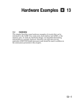
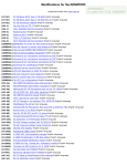
The multichannel frame delay (MFD) is a 4-bit field specifying (in binary)
the number of serial clock cycles between the frame sync signal and the
first data bit. This allows the processor to work with different types of T1
interface devices. Figure 5.26 shows a variety of delays.
Figure 5.26 SPORT Multichannel Frame Delay Examples
The memory-mapped receive enable register and transmit enable register
are each 32 bits wide and made up of two contiguous sixteen-bit registers,
as shown in Figure 5.27, which can be found on the next page. Each bit
corresponds to a channel; setting the bit enables that channel so that the
processor will select its word from the 24- or 32-word block. For example,
setting bit 0 selects word 0, bit 12 selects word 12, and so on.
Figure 5.27 SPORT0 Multichannel Word Enable Registers
5.12.2 Multichannel Operation
Received words for channels that are not enabled are ignored; that is, no
interrupts are generated for these words, no autobuffering occurs and no
data is written to the RX0 register. Likewise, there are no interrupts and
no autobuffering for transmit words that are not enabled. During transmit
word time slots for channels that are not enabled, the data transmit (DT)
pin is tristated.
Most aspects of SPORT0 operate normally in the multichannel mode.
Specifically, word length (SLEN), internal or external framing (IRFS),
5 – 32
Serial Ports 5
WORD 0
WORD 1
WORD 2
SCLK
DR
B3
B2
B1
B0
IGNORED
B3
B2
RFS
DT
B3
B2
B1
B0
B3
B2
TDV
frame signal inversion (INVRFS), companding (DTYPE) and
autobuffering are unchanged in the multichannel mode. Note: It is
important that RFS does not occur more than once per frame in
multichannel mode.
Instead of providing frame synchronization, the TFS0 signal functions as a
transmit data valid (TDV) signal in multichannel mode. TDV is asserted
while the transmitter is active. TDV can be active high or low, and its
polarity is controlled by the INVTFS bit, renamed INVTDV in this context.
If INVTDV is a 1, TDV is active low; otherwise it is active high. TDV can
be used to enable additional buffer logic, if required.
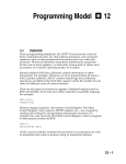
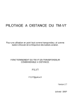
Figure 5.28 shows the start of a multichannel transfer. As in earlier
examples, word length is four bits (SLEN=3) and frame sync signals are
W0-3
W8-11 is one SCLK cycle.
W16-19
active high. Multichannel
frame delay (MFD)
For the
purpose of illustration, words 0 and 2 are selected for receiving and words
1 and 2 are selected for transmission.
RFS
Figure 5.28 Start Of Multichannel Transfer
DR
Figure 5.29 shows a complete 24-word block in the multichannel mode,
with complete words represented in the waveforms instead of individual
bits. Receiving is active for all words and transmitting is active for words
DT
0–3, 8–11 and 16–19 only.
Note: The ADSP-2105 has only one serial port (SPORT1) and does not
TDV
support multichannel operation.
5 – 33
5 Serial Ports
Figure 5.29 Complete Multichannel Example
5.13
SPORT TIMING CONSIDERATIONS
The SPORTs support full duplex operation and are normally interrupt
driven. That is, whenever a SPORT transaction has completed, the
processor generates an internal interrupt. Under most operating
conditions, the actual timing of the SPORT interrupts is not critical. In
some sophisticated DSP systems, however, it is important to know the
timing of the interrupt relative to the operation of the serial port.
5.13.1 Companding Delay
Use of the companding circuit introduces latency in two ways. First,
compressing or expanding a data value takes a single processor cycle.
Second, SPORT0 has priority over SPORT1 if both require an expansion or
compression operation in the same cycle; in this case, SPORT1 must wait
one processor cycle. See the section on companding earlier in this chapter
for more details on companding.
5.13.2 Clock Synchronization Delay
Some SPORT timings depend on the processor clock. Other timings
depend on the serial clock (SCLK0 or SCLK1). These clocks are
asynchronous. There is a delay associated with synchronizing the serial
clock to the processor clock whether the serial clock is internally or
externally generated. This delay is different for the transmit and receive
interrupts, as explained in the following sections.
5.13.2.1
Startup Timing
When a serial port is enabled by a write to the System Control Register, it
takes two SCLK cycles before it is actually enabled. On the next (third)
5 – 34
Serial Ports 5
SCLK cycle, the serial port becomes active, looking for a frame sync.
5.13.3 Internally Generarated Frame Sync Timing
When internally generated frame syncs are used, all that is necessary to
transmit data, from the programmer’s point of view, is to move the data
into the appropriate TX register with an instruction such as:
TX0 = AX0;
Once data is written into the TX register, the processor generates a frame
sync after a synchronization delay. This delay in turn affects the timing of
the serial port transmit interrupt. The latency depends on five factors: the
frequency of the serial clock, whether or not companding is enabled,
whether or not there is contention for the companding circuit, whether the
current word has finished transmitting and the logic level of the SCLK
TX Written, SCLK High
TX Written
Processor Clock
MSB Transmitted MSB Transmitted
(Alternate Framing) (Normal Framing)
High
Serial Clock
Low
High
TFS OUTPUT
(Normal Framing)
TFS OUTPUT
(Alternate Framing)
TX Written, SCLK Low
TX Written
Processor Clock
MSB Transmitted MSB Transmitted
(Alternate Framing) (Normal Framing)
Serial Clock
High
Low
High
TFS OUTPUT
(Normal Framing)
TFS OUTPUT
(Alternate Framing)
Figure 5.30 Clock Synchronization
5 – 35
5 Serial Ports
when the data value was loaded into the transmit register.
(Note that if the transmit frame sync is generated externally, data starts
transmitting when a frame sync signal is received.)
After the TX register is loaded, it takes three complete phases of the serial
clock, HIGH, LOW and HIGH, in that order, to ensure synchronization
(see Figure 5.30). Once synchronization has been ensured and a frame
sync generated, the most significant bit of the transmit word is shifted out
on the same rising edge as the frame sync if alternate framing is used and
on the rising edge of the next serial clock if normal framing is used.
Therefore, the worst-case synchronization delay is two SCLK cycles.
There is additional delay if the previous data transmission has not
TFS
DT
BIT3
BIT2
BIT1
BIT0
SCLK
Interrupt or Autobuffer Request
Figure 5.31 SPORT Interrupt or Autobuffer Timing, Transmit 4-Bit Words (No Companding)
completed; the TX register cannot be loaded into the transmit shift register
until the previous transmission is complete.
5.13.4 Transmit Interrupt Timing
Once the MSB has been transmitted, the subsequent bits are transmitted
on the rising edges of the SCLK. The transmit interrupt (or autobuffer
request) is generated internally on the falling edge of SCLK during the
transmission of the second bit (see Figure 5.31 below). This timing gives
the program time to load the TX register with the next data for continuous
data transmission.
The transmit interrupt, like any other interrupt, must be synchronized to
the processor clock. Servicing is subject to the same latencies as other
interrupts.
5 – 36
Serial Ports 5
RFS
DR
BIT3
BIT2
BIT1
BIT0
SCLK
Interrupt or Autobuffer Request
Figure 5.32 SPORT Interrupt or Autobuffer Timing, Receive 4-Bit Words (No
Companding)
The transmit interrupt essentially means that it is all right to write a value
to the TX register.
5.13.5 Receive Interrupt Timing
The receiver portion of the SPORT latches data on the DR pin on the
falling edges of SCLK.
Receive interrupt timing differs from transmit interrupt timing. The
receive interrupt or autobuffer request occurs only after an entire word is
RFS
DR
BIT3
BIT2
BIT1
BIT0
SCLK
Interrupt or Autobuffer Request
FIgure 5.33 SPORT Interrupt or Autobuffer Timing, Receive 4-Bit Words (Companding
Enabled)
5 – 37
5 Serial Ports
received. The interrupt request occurs on the rising edge of SCLK after a
word is received (see Figure 5.32) and indicates that new data in the RX
register can be read.
Companding causes a delay in the same manner as for transmitting.
However, the latency is transparent, as the receive interrupt is generated
after the expansion has taken place.
The LSB is received on the falling edge of SCLK. One processor cycle
elapses to allow synchronization to the processor clock. One processor
CLKOUT
Request
Processor Can
Service The
Request Here
Setup Time
Hold Time
Figure 5.34 Synchronization of Autobuffer or Interrupt Request to Processor
Clock
cycle later, the SPORT attempts to expand the data if companding is
enabled and the other serial port is not using the companding circuitry.
Companding latencies as discussed above occur prior to generation of a
receive interrupt. Servicing the receive interrupt is subject to the same
latencies as other interrupts.
5.13.6 Interrupt & Autobuffer Synchronization
The serial ports are treated as an asynchronous system to the processor,
even if the processor is providing the serial clock. Internal to the processor
is a circuit which synchronizes the autobuffer or interrupt requests to the
processor clock. Figure 5.34 shows the synchronization delay for the serial
ports, assuming the setup and hold times are met for the current processor
cycle. The setup and hold times for the serial port requests are the same as
shown on the data sheet for the IRQ2 signal. If the setup and hold times
are not met, there is an additional processor cycle of delay added.
As shown in Figure 5.34, there is a two-processor-cycle delay before the
autobuffer or interrupt request is acted on by the processor. The same
5 – 38
Serial Ports 5
latencies exist for all external interrupts. The processor can only service
interrupt or autobuffer requests on instruction cycle boundaries, so there
may be additional latency cycles added due to the completion of an
instruction.
5.13.7 Instruction Completion Latencies
There are several situations which can cause an instruction to take more
than one processor cycle. Any of the following can delay the processor’s
ability to service a pending interrupt or autobuffer request:
•
•
•
•
External memory wait states
Bus request when an external access is required (in go-mode)
Bus request with go-mode disabled
Multiple external accesses required for a single instruction
Request
CLKOUT
EXEC
A
B
FETCH INT
INT
Sync Delay
NOP Instruction, Fetch Vector
Execute First Instruction Of Interrupt Routine
Figure 5.35 Interrupt Service Example
• A pending higher priority autobuffer or interrupt request
• Interrupt being masked
On instruction cycle boundaries the processor will service multiple pending
interrupt or autobuffer requests in the following priority order:
Request
CLKOUT
EXEC
A
B
AUTOBUFFER
C
Sync Delay
Do The Autobuffer Transfer
Continue Main Program
Figure 5.36 Autobuffer Service Example
5 – 39
5 Serial Ports
•
•
•
•
•
SPORT0 transmit autobuffer—highest priority (not on ADSP-2105)
SPORT0 receive autobuffer (not on ADSP-2105)
SPORT1 transmit autobuffer
SPORT1 receive autobuffer
Unmasked pending interrupts in priority order
5.13.8 Interrupt & Autobuffer Service Example
Figure 5.35 shows the execution of a serial port interrupt based on a
request that meets the setup and hold time requirements. This example is
the same for a receive or a transmit interrupt request.
An additional latency cycle is consumed due to the fetching of the first
instruction of the interrupt routine. The interrupt can only be serviced on
an instruction cycle boundary. The above example (in Figure 5.35)
assumes all instructions are completed in one processor cycle. Figure 5.36
shows the result of an autobuffer request that meets the setup and hold
requirements.
Request
CLKOUT
EXEC
A
B
C
COMPAND
AUTOBUFFER
EXPAND RX
Sync Delay
Expand The Receive Register
Do The Autobuffer Transfer
Continue Main Program
Figure 5.37 Receive Companding Example
5 – 40
D
Serial Ports 5
Autobuffering only consumes the cycles necessary to perform the data
transfer; no additional cycles are lost fetching instructions. The above
diagram assumes that all instructions and data transfers occur in one
Request
SPORT0 Receive
Request
SPORT1 Receive
CLKOUT
EXEC
A
B
COMPAND
C
AUTOBUFFER
EXPAND RX0
EXPAND RX1
AUTOBUFFER
Sync Delay
Expand RX0
Expand RX1
RX0 Autobuffer Transfer
RX1 Autobuffer Transfer
Figure 5.38 Receive Companding Example With Both Serial Ports
Continue Main Program
processor cycle.
5.13.9 Receive Companding Latency
In addition to the cycles used for synchronization, there are some
additional delays possible due to receive companding. The synchronized
request is used by the processor to decide when to write the receive
CLKOUT
EXEC
AUTOBUFFER
D
E
FETCH INT
INT
Sync Delay
NOP Instruction, Fetch Vector
Execute First Instruction Of Interrupt Routine
Figure 5.39 Autobuffering Interrupt Example
5 – 41
D
5 Serial Ports
register with the expanded value. This can only occur on instruction cycle
boundaries and only one receive register can be expanded at a time. On
the ADSP-2100 family processors that have two serial ports (i.e. all except
the ADSP-2105), there is also a possibility of a delay due to the availability
of the companding circuitry. SPORT0 has the higher priority. When
companding is enabled, the autobuffer or interrupt request does not occur
until the register has been expanded. The next two diagrams show
examples of autobuffering with companding and the latencies involved.
The following diagram shows the latency when there are two pending
SCLK
DR
BIT3
BIT2
BIT1
BIT0
BIT3
BIT2
BIT1
BIT0
DT
BIT3
BIT2
BIT1
BIT0
BIT3
BIT2
BIT1
BIT0
Transmit Autobuffer Request
Receive Autobuffer Request
Figure 5.40 Using One Index Register for Transmit and Receive Autobuffer
receive autobuffer requests with companding enabled.
5.13.10Interrupts With Autobuffering Enabled
When autobuffering is enabled, SPORT interrupts occur when the address
modification done during the autobuffer operation causes a modulus
wraparound. The synchronization delay applies to this type of interrupt as
well. An example is shown below in Figure 5.39:
5.13.11Unusual Complications
In most cases the serial port companding, autobuffer, and interrupt
latencies are transparent to your application program. When trying to use
the same I register for more than one autobuffer channel, it becomes
important to make sure that the latencies do not effect the correct order of
operations. For example, if the serial port data is continuous, and the
receiver and transmitter are working with the same frame signal, the order
of the transmit and receive autobuffer or interrupt operations may be
affected by the latencies shown below in Figure 5.40.
5 – 42
Serial Ports 5
If the processor is free to handle the autobuffer requests in the order they
are generated, the receive autobuffer happens first and is then followed by
the transmit autobuffer. The order of these operations may change if the
processor is not available to handle the requests due to any of the
previously mentioned latencies. In this case there are 11⁄2 serial clock cycles
between the requests. If the processor is subject to bus requests, wait
states, or other latencies which are longer than 11⁄2 serial clock cycles, both
autobuffer operations may be held off. Since the transmit autobuffer has a
higher priority, it’s request will occur first. Because of the priority of the
autobuffer requests the use of a single I register more difficult or even
impossible in some cases. As long as there are no possible latency cases
longer than the difference in the timing of the requests, it is quite possible
to use a single I register for serial port autobuffering.
5 – 43